Quantcast
Channel: Open Source Projects Archives - Open Electronics
Viewing all 344 articles
Browse latest View live

What is new in Raspberry Pi B+

$
0
0

DSC_3915

After having produced and sold more than 3 million pieces, the Foundation just lately renewed the offer with a new Raspberry Pi B+: it materializes experiences, advices and requests coming from the users in these years. Let’s finally take some time to see what changed, for the better or for the worse.


The “new” Raspberry Pi B+ has a modified layout, to acknowledge many requests that were expressed by the users over the years. For example, the alignment and arrangement of the connectors, that are now better sorted and in greater number (USB); also, as for the number of available I/Os that are now 40, instead of the original 26. The competition tries the way of the compatibility with Raspberry Pi, while the new Raspberry Pi B+ moves away from it. We therefore present what is new in Raspberry Pi, what has changed, what has remained the same and what has been lost.


What is new in Raspberry Pi B+?

Fig1

First of all, energy consumption of the B+ Model Board has been considerably reduced (between 20 and 30% less than the B board), thanks to the usage of a new dual power switching, for a voltage of 3,3V and 1,8V, that is more efficient in comparison to the one of the linear type that was previously used. The 5V power supply is protected from polarity inversion and from short circuits by means of a 2A fuse. The I/O lines have been expanded, by substituting the GPIO socket with one used for the 40 pins connectors, whose pinout of the first 26 contacts remains identical to the original one of the B Model. The number of USB ports has been doubled, passing from two to four ports, in order to avoid the users to need to use cascade hubs when linking more devices at the same time (such as keyboard, mouse, wireless USB modem and external hard disk). To do this it was needed to modify the USB/Ethernet chip used, from the original LAN9512 to the LAN9514 – a 4-Port USB HUB. This allows to avoid the usage of an external HUB for all those devices that do not require current for more than what is supplied by the board. As compensation, it requires the usage of an operating system released later than 20 June 2014.

The quality of the audio signal has been improved, by operating on some functions connected to the DSP. Four holes for installation instead of two have been considered, so to improve the board stability when it inserted within other systems. The composite video output is integrated in the 4-pole 3,5mm jack plug. Last, but not least, the standard SD card housing has been substituted with one for a Micro SD Card.

Fig_2

What has remained the same in Raspberry Pi B+?

The same dimensions of the “original” board are kept: 85mm x 56mm. The same Broadcom SoC at 700 MHz is kept. The same RAM size, 512Mb, is kept and weld above the Broadcom SoC. The same microUSB power connector is kept. The same software is kept, but the kernel has to be updated, if previous to 20 June 2014. This becomes a problem for those who “personalized” the kernel with some additional driver.

Connettore

The HDMI port and the DSI connector for camera Pi have not undergone modifications. Even the audio output jack operates as in the previous models, but only if used only as audio output. As anticipated, the video output is directed towards the fourth pole of the audio jack plug (the one that is closer to the external body of the plug), as you can see in Fig. xx. 4-pole jack plugs do not benefit from a unified configuration, as you can still see in Fig. xx, thus, in our case, it is needed to use an audio cable as the one seen in Fig. xxx. Even in this case, pre-existing solutions that considered separated plugs for audio and video will have to be modified.

Fig_5


The Raspberry Pi B+ GPIO connector

Let’s take into account the new GPIO connector, now showing 40 pins on a 2X20-pin double row connector with 2,54mm pin spacing. The significance of the first 26 GPIO pins has remained almost unchanged. But even here a problem arises, should you want to use an expansion flat cable with the relative connectors. In this case, if you try to insert the connector of the flat table on the new GPIO, the operation is hindered by the interference between the flat cable connector and the pins GPIO 27 and 28. In this case it is needed to choose a flat cable with a 40 pole connector, or to sacrifice pins 27 and 28: there’s no turning back for this last operation. The good news is that we have the availability of additional 9 I/O and 3 ground pins. On the contrary, the J5 connector is completely lost: that’s the one bringing the pins of the i2S bus. We tried to track down some news from different websites, concerning a possible “return” of the i2S bus pins on the new connector. Most information we gathered claims that the i2S bus has been eliminated. By putting together the fragments of other news, it seems that the reference pins for the i2S connector have “migrated” towards the pins GPIO_18 (PCM_CLK), GPIO_19 (PCM_FS), GPIO_20 (PCM_DIN) and GPIO_21(PCM_DOUT). This problem also afflicts other products, such as the Adafruit Wolfson Audio Card. While waiting for more information and for shields reappraisal, it is necessary to continue using them with the “old” Raspberry Pi models.


Raspberry-Pi-GPIO-Layout-Worksheetfig_3
In the end, and as regards the future availability of the “old” models, the manufacturers assure that they will be made available until there will be demand.


From the store

 Raspberry Pi B+


An intelligent XMAS Lamp to Light up your Christmas!

$
0
0

The Christmas eve is approaching and – even if we’re a bit late on this – we make a Christmas Lamp, capable of emitting light of the same color of the surface it is laid on!

 DSC_5194

The project can be divided into three “modules”. A “sensor module” able to recognize the color tone of the lamp supporting surface. A “processing module” capable of decoding the output signal from the “sensor” and process it to produce as output “something” capable of driving a “programmable”  light source. Last, a “lighting module” capable of reproducing a bright hue from a default input.
For the color recognition module we have opted for the TCS230 “Module with Colors Recognition Sensor” produced by LC Technology Co. Ltd. To reproduce the hue detected by the sensor, the choice is very simple. An RGB LED will be fine in the prototyping stage and opens the way to different choices for the final production, as the RGB led driver can drive a wide range of light sources products, available on the market in a variety of forms, size, power and … price.

The main function of the “processing module” is as you can guess, to apply to the pins that drive each color a PWM signal proportional to the intensity of the corresponding color component detected by the sensor. We just have to choose what to use as a “processing module”. For a first prototype the choice is easy, just reach out on the desk and use the omnipresent Arduino Uno. His vocation is precisely to make quick and easy prototypes… working!


TCS230 Module with Color Recognizing Sensor

Fig_002

The module TCS230 is produced by LC Technology Co., Ltd. (http://www.lctech-inc.com), a company based in Shenzhen, China. This module is nothing but a break-out board with TCS230 onboard sensor, a programmable converter that can convert incoming light into a frequency signal proportional to the intensity of perceived light. The integrated circuit in CMOS technology includes an 8×8 array of photodiodes and a current-to-frequency converter following the block diagram. In the sensor, there are three color filters R, G and B (coincidentally!) and the color components measurement consists of a first measurement of the composed light intensity (no filter) and then of relative intensities of each color (measured by applying the three filters one at a time).


Fig_003


Tabella1

Figure shows the pinout of the integrated circuit while table defines the functions assigned to the individual pins. The TCS230 module pins are one to one corresponding to the IC pins. The diodes on the module are powered in parallel and serve to “illuminate” the field of “vision” of the sensor. The module can be powered by voltages from 2.7V to 5.5V and is therefore compatible with the outputs of microcontrollers either at 3.3V or at 5V.

 TDC230


The converter TCS230 reads the photodiodes that make up the matrix. Depending on the configuration of control pins S2 and S3 the diode matrix filters the red, green, blue or white and outputs at OUT pin a square wave signal with 50% duty cycle and frequency directly proportional to the perceived light (irradiance).

Tabella 2

The functioning of the sensor utilizes the fact that the different color nuances can be attributed to a combination of the three basic colors, red, green and blue, in appropriate proportions. When the filter is set for a given predominant color, for example blue, the integrated TCS230 examines only the intensity of the color considered excluding others. In this way it is possible to determine the blue component of the color detected. Same procedure for determining the intensity of the red and green components.

fig_005


Fig_05

The amplitude of the spectrum of the emitted frequency can be scaled by factors expressed in table properly configuring pins S0 and S1 levels, in order to match the processing capabilities of the microcontroller used. The inputs and outputs can be interfaced to a microcontroller for configuring and reading frequency values, which we will do with our microcontroller.


RGB LED

To reproduce the color tone read by the sensor we will use an RGB LED, at least in our prototype, or an optoelectronic device consisting of three LEDs that respectively emit Red, Blue and Green. There are two types of these components: “common anode” and “common cathode”. In the first, all LEDs have the anode, ie the positive terminal, in common while the three LEDs are controlled individually by driving the cathode terminal of each. In “Common cathode” components the three LEDs share the negative terminal while each individual LED is driven using the anode, which is the positive terminal. A configuration, the latter, more suitable to be used with Arduino Uno. In fact, the LED control uses three analog outputs (DAC) of Arduino Uno, that is able to convert the digital values between 0 and 255 into proportional voltage values between 0 and + 5V

Each hue in the RGB representation with eight bits of precision, is represented by a tern of values in the range 0-255 which reflects the intensity of each color component. For example, the intense red is represented by the configuration (255, 0, 0).

At http://www.rapidtables.com/web/color/RGB_Color.htm you can see a table that shows the correspondence between the color tones and their RGB representation. It is worth noting a peculiarity related to grayscale: who has been involved in image processing knows that the gray tones are expressed by sets of equal RGB values, for example (150, 150, 150). Not being able to reproduce with our LED any shade of gray, we will ensure that in these conditions the LED emits white light. The LED RGB chosen for our prototype is signed 540R2GBC-CC.


The schematics

schematics TCS230

In the scheme we can see the connections between the sensor TCS230, the microcontroller Arduino and LED RGB.

DSC_5183


The terminals S0 and S1, which serve to configure the frequency range emitted from the output of the TCS230 sensor are connected to Arduino pins 2 and 3. The outputs S2 and S3 that define whether or which filter to use in the reading of the light intensity are respectively connected to the digital outputs 6 and 5. The output terminal of the TCS230 sensor is connected to input 4 of Arduino. Finally the three terminals of the RGB LEDs are connected to the Arduino PWM outputs 9 (R), 10 (G) and 11 (B). PWM outputs are identified by a “-” on the card serigraphy. We used the three outputs mentioned since they share the same interval of the PWM output frequency. If we chose other pins we would have encountered an abnormal function because pins 5 and 6 have output frequency of 976Hz while the other pin 3, 9, 10 and 11 have output frequency to 488Hz. To avoid surprises and malfunctions difficult to detect is always advisable to read the product description and documentation of the components when dealing with a new project. In our case we connected the terminals of LED RGB to three PWM outputs characterized by the same clock frequency. The three resistors by 470 ohm limit the input current to the output terminals to about 20 mA.


Arduino Uno Code Sketch

The sketch in Listing 1 allows you to manage the logic of our lamp, the process of color recognition and its reproduction as bright hue on LED RGB. Working on the prototype with Arduino we can introduce a set of instructions useful for debugging purposes that later we will eliminate when realizing the final product. In our case we will use the Serial Monitor to display the readings and the results of calculations performed. The constant isPresentTolerance allows setting a threshold value to determine if the lamp is put on a surface or not. We used the expedient of performing a reading with the LED switched on and one with the LED off. To turn the LEDs on and off we will configure properly the pins S0 and S1. If lamp is placed on a surface we will have two very different values, while if the lamp is “suspended”, the ambient light will reach the sensor in any case giving so two close values read. If the lamp is laying on a surface, we will measure both the total intensity of the reflected light and the relative intensities of the individual color components, applying to each reading the appropriate filters configuration through the TCS230 pin S2 and S3. The relative intensity of each component is calculated in relation to the total color intensity, read without the presence of any filter. To read the emitted frequency in correspondence of the application of each filter it is used the instruction “pulsein”, which reads the pulse length on a specific pin. The instruction can be configured to read the pulse duration in LOW level or HIGH level, in our case LOW. In this case, the instruction waits until the pin level takes the value LOW, then starts measuring time until the level returns HIGH, interrupting the measurement. The result of the reading is in microseconds. The instruction is: 

pulseIn(pin, value, timeout)

where:

pin: where you want to read the pulse (int)

value: level HIGH o LOW, when you want to read the value (int)

timeout (optional): time window within you are expecting the pulse. The default is 1 sec (unsigned long). It there is a timeout and no pulse read, it returns 0.


The instruction “pulsein” works for pulses lasting between 10 microseconds and three minutes though for very long pulses it can cause reading errors. The logic for the color recognition requires a first reading in the absence of filters, a condition which is achieved by setting pins S2 and S3 respectively high and low. It is read the value present on the OUT pin. Sequentially will be set filters corresponding to the three basic colors and read the values of the relative intensities, in relation to the overall value of the intensity (intensity Total Value / Value Color Intensity). For comparison and selection of the higher relative intensity is then calculated the predominant color to which is assigned the PWM driver value 255. The values to drive PWM signal for other colors are calculated on the proportion between the value read for the color detected and the value of the predominant color referenced to 255. As a last step, the PWM values so calculated are used to drive the respective pins connected to the RGB LED terminals.


/*

Sketch Christmas Lamp

*/

int S0 = 2;    // output frequency control pin

int S1 = 3;    // input frequency control pin

int S2 = 6;    // pin color filter control

int S3 = 5;    // pin color filter control

int taosOutPin = 4;   // pin output for PWM

int LED = 13;  // pinD

int R = 9;     // PWM red

int G = 10;    // PWM green

int B = 11;    // PWM blue

double Coeff = 0;

int Ro = 0;    // pin E

int Go = 0;    // pin E

int Bo = 0;    //  pin E


void setup() {

TCS230setup();

Serial.begin(115200);

Serial.print("\n\n\nready\n\n\n");

pinMode(R,OUTPUT); //S2 pinE

pinMode(G,OUTPUT); //S2 pinE

pinMode(B,OUTPUT); //S2 pinE

delay(100);

}

void loop() {

Serial.print(detectColor(taosOutPin)); // serial debug

Serial.print("\n\n\n");

delay(1000);

}

int detectColor(int taosOutPin){

// surface detection

double isPresentTolerance = 5;

double isPresent = colorRead(taosOutPin,0,0)/colorRead(taosOutPin,0,1);

Serial.print("isPresent:");

Serial.println(isPresent,2);

Serial.print("valore isPresentTolerance:");

Serial.println(isPresentTolerance,2);

if(isPresent < isPresentTolerance){

Serial.println("nessuna superficie rilevata");

return 0;

}

  double red,blue,green;

  // light intensity detection no filters

  double white = colorRead(taosOutPin,0,1);

  // red

  red = white/colorRead(taosOutPin,1,1);

  // blue

  blue = white/colorRead(taosOutPin,2,1);

  // green

green = white/colorRead(taosOutPin,3,1);

Serial.print("red");

Serial.println(red);

Serial.print("blue");

Serial.println(blue);

Serial.print("green");

Serial.println(green);


if(red > blue && red > green){

     Coeff = 255 / red;

     Ro = 255;

     Go = green * Coeff;

     Bo = blue * Coeff;

     LED_RGB(Ro, Go, Bo);

     return 1;

  }

  if(blue > green && blue > red){

     Coeff = 255 / blue;

     Bo = 255;

     Go = green * Coeff;

     Ro = red * Coeff;

     LED_RGB(Ro, Go, Bo);

    return 2;

  }

  if(green > blue && green > red){

     Coeff = 255 / green;

     Go = 255;

     Ro = red * Coeff;

     Bo = blue * Coeff;

     LED_RGB(Ro, Go, Bo);

     return 3;

  }

}


double colorRead(int taosOutPin, int color, boolean LEDstate){

  //make sure that the pin is set to input


  pinMode(taosOutPin, INPUT);


  taosMode(1);

  int sensorDelay = 3;

  //set pins to trigger filters

  if(color == 0){// bianco (no filtri)

     digitalWrite(S3, LOW); //S3

     digitalWrite(S2, HIGH); //S2

  // Serial.print(" w");

  }else if(color == 1){// red filter

     digitalWrite(S3, LOW); //S3

     digitalWrite(S2, LOW); //S2

  // Serial.print(" r");

  }else if(color == 2){// blue filter

     digitalWrite(S3, HIGH); //S3

     digitalWrite(S2, LOW); //S2

  // Serial.print(" b");

  }else if(color == 3){// green filter

     digitalWrite(S3, HIGH); //S3

     digitalWrite(S2, HIGH); //S2

  // Serial.print(" g");

  }

  double readPulse;

  if(LEDstate == 0){

    taosMode(0);     

//      digitalWrite(LED, LOW);

  }

  if(LEDstate == 1){

  taosMode(1);

//      digitalWrite(LED, HIGH);

  }

  delay(sensorDelay);

  readPulse = pulseIn(taosOutPin, LOW, 80000);

  // pulse timeout read setting

  if(readPulse < .1){

     readPulse = 80000;

  }

  // turn off sensor led

  taosMode(0);

  return readPulse;

}

// manages the frequency output mode TaosMode(0);

// sero, sensor quiet


void taosMode(int mode){

  if(mode == 0){

  //power OFF

     digitalWrite(LED, LOW);

     digitalWrite(S0, LOW); //S0

     digitalWrite(S1, LOW); //S1

  // Serial.println("mOFFm");

  }else if(mode == 1){

     // frequenza 1:1

     digitalWrite(S0, HIGH); //S0

     digitalWrite(S1, HIGH); //S1

  // Serial.println("m1:1m");

  }else if(mode == 2){

  // frequenza 1:5

     digitalWrite(S0, HIGH); //S0

     digitalWrite(S1, LOW); //S1

  //Serial.println("m1:5m");

  }else if(mode == 3){

  // frequenza 1:50

     digitalWrite(S0, LOW); //S0

     digitalWrite(S1, HIGH); //S1

  //Serial.println("m1:50m");

  }

  return;

}


void LED_RGB(int Rx, int Gx, int Bx){

  analogWrite(R, Rx);

  analogWrite(G, Gx);

  analogWrite(B, Bx);

  return;

}


void TCS230setup(){

  // init pin frequency management

  pinMode(LED,OUTPUT);

  // color filter management pin

  pinMode(S2,OUTPUT); //S2

  pinMode(S3,OUTPUT); //s3

  // output pin light-frequency conversion

  pinMode(taosOutPin, INPUT);

  // pin to select ouput mode

  pinMode(S0,OUTPUT); //S0 pinB

  pinMode(S1,OUTPUT); //S1 pinA

  return;

}


To run it, open the Arduino IDE and copy the sketch in the editor IDE. Connect Arduino Uno to the PC with the USB cable, set the COM port and the Board as shown above. Compile and upload the sketch into the microcontroller. Open the Serial Monitor. Place the sensor on objects or paper sheets of different colors and … enjoy yourself testing it. Now let us see if our 3D printer has finished printing the lamp. Nice Christmas tree, just assemble “summarily” the whole prototype and go around collecting comments!

DSC_5198b


From the Store

Arduino UNO

TCS230

Merry Christmas and a Open New Year

$
0
0

Here we are, a great year full of innovations and open source project is passing by and we would like to celebrate with you this magic moment! As usual in this period, it’s time to take stocks of the work done so far, so here are the most visited posts on Open Electronics.

Top 5 Posts

PLC_fea

As you can easily guess, most of the interest from visitors has been focused to Arduino and open hardware solutions. One of the most interesting post is about Arduino as PLC. The reason is simple: industrial PLC are often expensive and not so easy to be programmed at home, while Arduino offers as usual a fast, cheap and flexible solution to realize this kind of controller. Moreover, a PLC can be useful in many open source projects so that’s the reason why people appreciated so much our post.

2

Oscillo

For the same reasons, another best viewed post has been the Homemade Oscilloscope with Arduino, realized by putting together Arduino as hardware interface and a PC with Matlab to perform the filtering and displaying the waveforms. A must see, since every serious Maker must have an Oscilloscope!

3

WifiShield2

Ok, now you realized your project, the board is working, you have connected the breakout, signals and commands are flowing back and forth, your code sketch has been loaded on Arduino and… oh my! How to tell the World my board is up and running??? Don’t worry, you simply need a communication board for your controller! The solution is A New Wi-Fi Shield to Connect Arduino to Internet! You can find on the post an “all inclusive” immersion on board, connections and source code to connect your board to Internet in a moment.

4

MowerFea2

The Maker life is hard. When we back home from a heavy working day, all we want is to sit on our soldering desk, switch on all the magic Leds giving life to the bunch of devices we have all around us and stay up all the night trying to understand why nothing is working… but the guide was so clear! Anyway, our partner is pushing to go out, breathe some fresh air, see the sunlight (especially on weekends!). Mhhh good idea, maybe we can keep on thinking on hardware issues sitting around in our garden! But… oh my! It has been such a long time since we don’t cut lawns!! It is a jungle out there! No problem, a good Makers has always a solution, and with this one you can have fun with electronics AND save yourself by a sweating afternoon working outside: A Robotic Lawn Mover Sun Powered with ArduinoAtHeart.

5

Raspberry Radio

Here is my favorite, since I’m and audiophile and music lover. I’ve spent a lot trying to find the best device to play my hi-def FLAC or enjoy my videos, but all the stuff I’ve purchased, showed many limits in a real short time. But luckily I had the solution right under my nose! With Raspberry (better if the B+ version) you have a cheap but powerful and above all fully configurable media player! Check it out here, Raspberry Pi As An Audio/Media Center.

Top 3 Opinions

Here we would like to highlight the most viewed and appreciated post regarding market and technology trends and interviews written by Open-Electronics staff.

1

Tomas Diez

The next step any Maker would like to do in his New Year’s Resolution is… to open a FabLab! It is an amazing idea, that needs inspired people and a live community giving passion to it. But it is not easy indeed, since there are also some obstacles to take over and also some paperwork to be necessarily done. Open-Electronics.org is your friend also here, you can find lots of advices in our post How to start a Fab Lab: some tips and tricks and an interesting interview to Tomas Diez, one of the most influencing people in Europe about FabLab.

2

Andrea Iacopini

Then, after setting up your FabLab, some rest is due! And what is the best way to relax, than sailing? But always in Maker-style, so we need to build our own boat, with the amazing tools available on our Lab. Am I joking? Of course not, here you can find interesting considerations on how to build a community and a Foundation to start a Sailing Boat Open Source Project. Get ready for the next America’s Cup! For Mountain lovers people, on the same post you can find information about a “traditional” open source vehicle… you can choose!

3

cropped-OSHWA_Logo_2012_WPsize41

Let’s get back “business serious” now, and think to the real meaning of the Open Source movement. It is so much loved by DIY fans, but the most amazing applications and projects come from the business and industrial world. Who is working in any role on the Open Source / Open Hardware business for Companies, knows how difficult is to explain to a “open source newbie” company how much is important to “go open” and which are the advantages following that approach. This post is a useful toolkit to convince them! Thanks to Simone Cicero and his “Why Choose to be Open Source in the Hardware Industry“.

That’s it? No, as someone said before me, we still need

One Ring to rule them all, One Ring to find them,
One Ring to bring them all and in the darkness bind them

I perfectly know which is the event that is gathering all our passion, all the followers and Makers from all Europe and from all over the World! Here is the MakerFaire 2014 Rome edition, let’s see also next year in the third edition!

We are now to the final greetings, with one more recommendation! How will a real Maker prepare the Christmas cake? Of course, using our 3Drag Choco Printer!!

3Drag can print chocolate....

We wish you a Merry Christmas and a Happy New Year!

Xmas_fea

Here comes the open source Snow Plow Robot

$
0
0

We present a caterpillar robot based on Arduino Uno, remotely controlled through a Play Station 2 wireless controllers.

DSC_5362

Since we are not insensitive to solutions making life easier, we have considered the idea of creating and proposing something that could help us avoiding the cold and fatigue of using the usual manual shovel and at the same time, we opted not to replicate something already available but a new fun and technologic device. We therefore decided to start developing a Snowplow Robot, remotely controlled, proudly showing a robust mechanics and fine electronics all implemented with cards easily available on the market.
The result is a miniature version of a true snowplow, caterpillar tracks, with blade and light projector mounted on top to light the way in the dark; everything is controlled by a remote control from the PlayStation 2. Let us see how our caterpillar robot is assembled, starting from the mechanics and then describing the electronics and firmware that is necessary.


Mechanics

On the mechanical side, the robot consists of a snowplow frame that supports a motorized blade (that can be raised and moved) and the traction system: electric motors, wheels and tracks.

The frame

Fig25

fig. 1

Initially it was thought to assemble the entire structure creating an aluminum tubular frame held together by corner brackets, but given the high mechanical stresses and the robustness required, we decided to use for the base four tubular iron (rectangular section) welded together, thus obtaining a rectangle by 600×375 mm.

fig. 4

As a base for the various mechanical components, we used an aluminum plate 3 mm thick 600×375 fixed on the iron frame. Two aluminum profiles vertically mounted (30×30 mm section and 190 mm length), plus two horizontal (30x30x580 mm long side) and two more (30x30x375 mm short side) were used as a skeleton on which we will apply the outer cover of the robot (made using 5 panels aluminum 3 mm thick); to fix the struts to the base, we must practice a hole in their section (8MA), then threaded. Two “L” aluminum brackets shall be fixed always on the front of the frame, and serve as a support for the two linear actuators that allow the blade to rotate right and left.

fig. 3

The traction system

The movement of the snowplow is granted by four trolley wheels, fitted with tires and hub provided with ball bearing with a hole of 16 mm diameter; each wheel has an outer diameter of 26 cm and about 8.5 cm wide tire. Easily available in many DIY centers, these wheels are capable of bearing (individually) a weight of 150 kg, for a total of 600 kg, much more than what we need for our robot. For the wheels axles we have used 16 mm diameter threaded bars, 63 cm long, passed through the aluminum supports and there blocked, caring that those rods protrude equally on each side. The supports are fixed to the lower base of robot’s frame.

fig. 5
To lock the wheels at the right distance (the side facing the support) you can opt for two solutions; nut and locknut, or, as in our case, directly weld a nut on the threaded bar. For this solution, once that is done you need to put a nut (16 MA) in threaded rod, screw it until it get to about 7 cm from the support bar, check precisely the measure and then weld it. The same applies to the other side and the other bar.

fig. 6b


To mount the gear on each wheel, you have to remove the four original bolts and derive four holes of equal diameter, matching those of the respective wheel; to position the holes with precision it is convenient to create a cardboard template matching the distance between the holes on the wheels.

fig. 7

Drill the gears and then put the four 8MA 100 mm long in and screw a nut lock to secure the bolt to the wheel rim; then put another nut (or nut and lock nut) at a distance of about 72 mm from the nut screwed into the inner side of the rim. Now you can apply the worm wheel, centering the respective holes and screw tight with four nuts. Having done this, you can mount the wheel: if everything is correct, you will have the nuts of the gear at a maximum distance of 10 mm from the frame.

fig. 8

On each axle, you must enter the lock nuts 16 MA. Externally, the two wheels are spaced and held in tension by an angular bar of aluminum 30×30 mm, 2 mm thick and should be fixed by a bolt in the center of the threaded bar. When we lowered the blade to shovel we realized that it was necessary to increase adherence using caterpillar tracks (or suitable wheels, such as those of tractors), but we decided to find an alternative solution.

fig. 9a

Inspired by the various solutions found on Internet and adapting them to our needs, we have created the tracks by ourselves using four packs of bicycle chains 1/2 “x1/8″ with 114 links each (two per side, for a total of 120 links, corresponding to a length of about 166 cm), 40 aluminum corner (mm) 120 12×12 long with a thickness of 2 and 80 5MA bolts 50 mm long and relative nuts. The angular aluminum brackets, spaced 8 cm center to center from a bolt, are needed to hold together and parallel the two chains of each pair constituting a track (wrapped around the relative pair of wheels) and are responsible to obtain the right grip on the snowpack. On each corner, you must drill two holes in which you must insert two bolts 5MA x 50 mm and secure them to the chain, preventing it from slipping to one side or the other.
To match the wheels to the motor pinion MY1016, it was necessary to procure two short pitch chains (like those of electric scooters or mini-motorbikes), to mount two gears of diameter 155 mm to 76 teeth  on the driving wheels and space them of about 35 mm from the wheel (the inside of the tire) with 4 bolts 8MA x 100 mm. To fix the engines we used brackets, realized from two rectangular bars of iron (mm) 30×20 375 long and drilled. Starting from the outside, the first hole is approximately at 14 mm, while the second is at 42 mm from the first; this distance corresponds to the holes of the engine (the narrowest part of the motor bracket).

fig. 9b

On the bar we drill two holes, at 110 mm from the outside and at both sides, required to fix the two vertical bars 190 mm. The same perforation was made for the second bar. The two vertical bars 19 mm, once welded to the base of the frame, have been drilled at a distance (from the base of the frame) of about 44 mm for the first hole (slot shaped) and 139 mm for the second hole (always slot shaped). At this point all that remains is to fix engines, directing the pinion to the outside and ensuring that it is in line with the gear wheel.


Blade

Pala_quotata

The most complex mechanical part is the blade support and its mechanism. To make the blade we used a sheet of rectangular steel 650×250 mm, 2 mm thick, which we then slightly curved (above and below, the long side) to facilitate the snow shoveling.

fig. 10

For the mechanical structure that supports the blade and allows it to move, we used:

  • a box-shaped iron frame 30×20 mm, 265 mm length, cut off at the end with the required angle
  • one iron square rail 40×20 mm 13 cm long
  • a rectangular profile 30×20 mm 46 mm long
  • an interlocking truss 600 mm long (used for shelves and available in DIY shops), with a bearing support by 16 mm
  • two boxes 40×30 mm long 26,5 cm cut end at the demanded angle.

fig. 12

We then made an aluminum rod 11 cm long (12 mm, except in the first 5 mm where it is 14 mm) to be inserted into the 12 mm bearing; in its upper part it has been drilled a 5 mm hole, threaded, to fix by means of a bolt 5MA the bracket for the linear actuator which allows to raise and lower the blade. The second bracket is fixed to the center of the bar with length 265 mm. To rotate the blade to the right and left, we used for each side two L-brackets aluminum 50×50 mm, 40mm width and 5mm thick, drilled and screwed by inserting a washer between the two. A pair of “L-bracket” was fixed, by means of two bolts, in the lower part (left side) of the frame and the other to the right.

fig. 13

The linear actuator is fixed to one end of the L-bracket while the other end was fixed on the triangular structure of the blade, for both sides.
Before drilling and secure the three linear actuators to the blade triangle, you have to take the two linear actuators to move it to right and left, apply 12 VDC to one of the two in order to have the maximum extension, while the other must be fully pulled back. Now you must wire the power supply wires of the two actuators in order to have the positive of the 1st actuator connected with the negative of the 2nd and the negative of the 1st to the positive of the 2nd. Then feed the wired pair of actuators and switch off the tension when they reach the same extension. Now you can attach the brackets of the linear actuator (cod. SUPPLACT) to those of the two side-actuators (on the back).

Fig. 15

The bracket must be fixed to the pair of aluminum “L-brackets” (the one with the interposed washer), previously fixed on the front lower frame.  Now you can position the part of the actuator arm near the triangle of the blade, fix a small “L” (will serve as the anchor) and take accurate measures before drilling permanently. All that remains is to place also the central actuator, fixing the bracket on the central pivot of the bearing and then securing it (after inserting the specific bracket also on the part of the piston) on the central area of the triangle of the blade.

Fig. 16

The interlocking crossbar is fastened to the horizontal bar of the blade triangle, drilled and fastened. The blade steel, properly bended, should be placed on the crossbar to mark the drill holes.


Electronics

Schematic 

Electrical and electronic part of the snowplow is based on Arduino Uno, hosting three shields and interfacing with:


The shield mounted on Arduino are the motor shield to control the three linear motors that manage the movement of the blade and the PS2SHIELD, which allows you to interface with the PlayStation 2 (PS2); the latter requires the RX-PS2, which is a 2.4 GHz radio receiver for sending/receiving specific commands from the aforementioned console.
The wiring diagram of the robot is what you find in these pages; the power source is made by a series of two lead gel batteries by 7.2 Ah: we take the 12 V from the mid-point connection of the two, while between the negative and the positive of the series we take 24 volts. A switch (125V, 2×15 ampere) controls the two supply lines.
With 12 volts, we run Arduino, which will power the shields through its pin-strip; a LED (internally mounting the limiting resistor) will indicate when Arduino is running. The 12 volt directly from the battery stack is also feeding the power section of the motor shield. In fact, since the absorption of the three linear actuators (cod. LACT2) is high, it is not advisable to take the 12 V from Arduino: you opt for the external power supply to be provided to the appropriate PWR terminal. To use the external power supply, you must move the jumper (on the shield) near the terminal, between the central and the EXT. The management of the shield requires a special library for Arduino, supplied with the component. Each linear actuator is composed by a 12 Vdc gear motor using a worm screw to move a shaft back and forth along its length (maximum excursion of 5 cm). The actuator has a dynamic load of 50 kg and a maximum speed of 1.3 cm / s. It is able to support up to about 250 kg, when not moving, and the torque ensures the maintenance of the position of the shaft even in the absence of power. Two limit switches provide the engine to stop when it reaches the maximum extension and contraction, while the diodes allow reverse direction after reaching the limit point. The actuator is made of metal and is sealed to protect it from dust and water (IP63 rated).

Struttura2
Let us now turn to the 24 volts supply line, which is feeding the power part of the snowplow, which are the traction and the projector (optional) sections: the first is based on the motor driver, to be connected with four wires to the same number of Arduino digital lines.
The motor driver is a double bridge power driver capable of driving two brushed motors continuously with a voltage of max 35 VDC and a current of 15 A (each). By interfacing with Arduino and using only four digital I / O (2 PWM), you can choose the rotation direction and speed of the motors. The circuit has four control pins, four LEDs that indicate the rotation direction of motors, two pins for the board power supply (5 Vdc) and two aluminum heat sinks located in the rear of the printed circuit, necessary to dissipate the heat generated during operation at full power. For the management of the driver by Arduino, the manufacturer provides a special library. The output terminal blocks allow you to connect the two engines, to be connected as indicated by the diagram (do not invert polarity, otherwise the tracks will run in reverse!) using cables with a section of at least 1.5 sq. mm.
About control inputs, it should be respected the connection between Arduino and the controller connector pitch 2.54; correspondence that is needed when using the library provided by the manufacturer and our firmware: if you edit them, you have to revise connections. Remember that DIR are the logic levels to set the motors rotation direction and PWM are the PWM signals to command the power drivers.
To identify the controller connector contacts it’s sufficient to refer to the silkscreen visible next to it on the component side of the circuit board.
In addition to the engine controller, the 24 volts will power the section of the LED projector, you can mount or not; if mounted, respected wiring indicated and remember to take the positive 24 V from the relay card (cod. RELAY1CH). The latter houses a relay and the respective drive transistor controlled by Arduino through the Digital I/O 13; Arduino also powers the card, by means of the +5V and ground (GND).

DSC_5332
A relay allows turning on and off the projector, targeting action on the corresponding circuit.
The projector is designed to operate at 220 Vac, however, since this voltage is not available on the robot, to avoid using an inverter we modified the projector by opening it, removing the AC / DC and bringing the two wires of the power LED directly to the output of the converter DC / DC (cod. STEPUP30V); the latter is a switching converter with adjustable output voltage, which should be tuned in order to provide to the LED a current such as to make it work at about 10 watts. Usually this is achieved at about 30 volts. However remember that the power is given by the product VxI, (current by voltage, in watts is obtained if V is in volts and I in amperes), then to 30 V, the current consumption should be just under 340 mA. Although the group of LEDs is internally protected from overcurrent, the STEPUP30V has a limitation of the output current to 2A so it can be useful to replace it with a DC / DC equipped with output current limiter; a good example is available on the website www.futurashop.it as STEPUP30VADJ.
Receiving data from the remote control is the job done by the shield PS2SHIELD, for which the manufacturer makes available the specific library. The shield performs the receiving and decoding of the command; the radio part is left to the RX _PS2, which is inserted into the related connector.
The last thing to note is the photoresistor, used by Arduino to detect the ambient lighting and to control the board RELAY1CH so the LED projector is turned on; the component is fed to the voltage divider by a resistor of 10 kOhm (1/4 W) and is read from the analog input A0 Arduino. The 5 volts are taken from Arduino 5V.
This light sensor does a simple thing: in good lighting conditions, the resistance of the photoresistor is low and the voltage read by the ADC of Arduino microcontroller is low and does not trigger the relay board; darkness instead, increases resistance a lot and the ADC reads a voltage close to 5 volts, which causes the projector to switch on.
For the hardware part that’s all: in a coming post episode we will share and explain the Arduino sketches.


A simple 1 Channel  remote control Receiver at 433,92 MHz

$
0
0

FT1111_2

Here we present a small, low cost single channel receiver,  encoding MM53200 and HT-12, with code self-learning function. Decoding is achieved by means of a PIC microcontroller by Microchip, that deals even to the memorization of 5 codes and governs the relay output as well.


Features

- Number of outputs: 1

- Output: Monostable, Bistable

- Power Source: 12Vdc

- Absorption: 40 mA max.

- Memory: 10 remote controls

- Encoding: MM53200/HT12


The MM53200 encoding, that owes its name to the integrated encoder/decoder from the then National Semiconductors, is probably the oldest to be used in radio and infrared transmissions  that are implemented in remote controls; and precisely the diffusion and the success obtained drove other builders, such as UMC, to develop “clones” like UM3750 and (at a later stage) UM86409 (capable of operating even at 5÷6 volt). Despite the limited number of combinations (only 4096) the MM53200 encoding offers many qualities, one of them being the possibility of controlling the encoding pins with binary logic levels or simple binary dip-switches, and the fact that both the encoding function and the decoding function are carried out by a single integrated circuit: depending on the settings of a dedicated pin (no. 15), the MM53200 and its clones may operate as encoders or decoders (two pins are there to receive or transmit the codes).

As much as it can be considered limited and unsafe today (in comparison to the rolling-code systems or to the more dated Motorola MC14502x encoding), since it has only 4.096 combinations, the MM53200 encoding is still much used, and particularly for door/gate openers; thus, a product from Holtek, named HT-12, was added to the traditional encoders/decoders, and it is fully compatible.

To meet the requests of those who have to maintain remote controls based on type encoding, and specially for those who have different transmitters but can’t find anymore the receivers of a gate opener control unit, we thought to create e single channel receiver with a relay output, capable of identifying the standard MM53200 codes and to be coupled, by means of a simple procedure, to a maximum of five transmitters.

Our circuit stands as a candidate to substitute the existing receivers, decoding MM53200; and the availaility of the self-learning function allows to couple the existing transmitters with great ease, without having to worry about the clock frequency of the encoder.

We have in fact to remember that the MM53200 transmits data strings that are timed by the clock generated by an internal oscillator, whose work frequency depends on the R/C network connected between the pin 13, the power source positive and the ground; in a traditional system with a receiver depending on MM53200, UM86409 or UM3750, the clock network has to determine a frequency that is the same of the one placed on the transmitter encoder, otherwise, even if setting the coding inputs in the same way (that is to say, the code dip-switches) the decoder will not be able to identify the incoming strings.

In our receiver, decoding and code coupling (as regards the five transmitters) are entrusted to a microcontroller, whose firmware is capable of adapting itself to the clock frequency of the encoder placed on the transmitter (provided that it works at 1,7 KHz), to synchronize with it and then to extract the code to memorize it, that is to say, to analyze it so to command the relay output.


Electric Diagram

1111_Schema

The electric circuit of our receiver is really essential, thanks to the microcontroller, that alone carries out the task of the decoder (but has a case that is half as big as the one of MM53200) and of code memory, in addition to not needing dip-switch and clock network.

In the RF section we use a receiving module by Aurel, at 433,92 MHz, capable of receiving transmissions in OOK (On Off Key) amplitude modulation. In particular, we use AC-RX2(U3), an hybrid and very cheap module that at the same time is reliable, adequately selective and sensitive enough. The U2 module contains the radio part of the circuit and is a specific Aurel receiver, fitted with an antenna signal amplifier (granting as much as -106 dB), super regenerative stage tuning, tuned at 433,92 MHz by means of a compensator that has been calibrated by the manufacturer and equipped with a RF filter (the filter is needed to improve the selectivity, that is not high in the super regenerative units) and amplitude demodulator. The module package is completed with a comparator square of the digital signal (at TTL level) coming from pin 14 and with a LF amplifier of the signal coming from the AM demodulator.

1111_TopSilk FT1111_1

Both the receiver and the microcontroller have to be powered at 5V, a voltage obtained by means of the U1 regulator, a 78L05 in TO-92 format that obtains its 5 volts by starting from a 12V input voltage (applied to the PWR platform and needed to power the relay) at well stabilized 5V. The C1-C2 filter, placed at the stabiliser intake, removes possible inconveniences; the C3-C4 filter (at the stabiliser outlet), on the other hand, removes possible residual noises. The D1 diode, always present in our projects, protects the circuit from possible accidental inversions in the power supply voltage. As already hinted, this project has been created with a PIC12F675, a microcontroller in 8 pin DIL format, by Microchip. This integrated circuit has the availability of 6 I/O ports, but only 5 of these have been used. Let’s start from the GP0 line (pin 7), to which the LD1 LED  is connected; the latter communicates with the different operating states of the system, such as the identification of MM53200 codes, their memorization and erasure, and much more. The SW1 microswitch is connected to the GP1 line, and it starts the call for the memorization and erasure routines of the codes; on such line an internal pull-up resistance is active, thus forcing GP1 to the high state when SW1 is not pressed. The GP2 line represents the input for the serial data string, obtained from the demodulation operated by the RF module (U3). The PIC doesn’t require quartz to synchronize the clock, since we’re using the internal oscillator at 4MHz, calibrated by the same manufacturer, and having a 1% accuracy. The usage of the internal oscillator, in addition to further reducing the circuit encumbrance, frees GP5 and GP4, the two output lines here employed for the creation of the bistable (GP5) and monostable (GP4) outputs.

To decide which type of command has to receive the output relay, a jumper to be weld has been designed, to be realized on the printed circuit board. To activate the bistable mode the central contact on B has to be closed, while to obtain the monostable operation (“impulsive”) the central contact has to be closed on M. The thus selected output drives, by means of the R1 resistance, the base of a BC547 mounted as a common emitter, whose collector supplies the coil of the RL1 miniature relay. In parallel to the coil the classic diode is found, and it is needed, at the transistor’s interdiction, to turn off the peak of reverse voltage that the same coil tends to generate as a reaction to the interruption of the current, following the well known Lenz’s law.

Please notice that in monostable mode the output is not timed as one would expect, thus it returns to sleep state once the button is released.


The firmware

The source code has been compiled in PIC BASIC PRO language.


'****************************************************************
'*  Author  : Alessandro Sottocornola                           *
'****************************************************************

INCLUDE "modedefs.bas"


'************************** D E F .    R E G I S T R O *************************
DEFINE OSC 4
DEFINE PULSIN_MAX 1350

ADCON0 = %00000000
OPTION_REG.7=0
CMCON0 =%00000111
ANSEL=%00000000 
WPU=%00000010 

             
'************************** D E F .    P I N    P I C **************************
symbol PULSANTE = GPIO.1
symbol LED = GPIO.0
symbol BIST = GPIO.5
symbol MONO = GPIO.4
SYMBOL RF = GPIO.2
  
INPUT RF
INPUT pulsante
OUTPUT MONO
OUTPUT BIST
OUTPUT LED

'************************* D E F .    V A R I A B I L I ************************
TX_MAX CON 10       'TX mem
TEMPO CON 40        

CONTA VAR WORD      
ERRORE VAR BYTE     
I VAR BYTE          
TRENO VAR WORD[25]  
COD_A VAR BYTE      
COD_B VAR BYTE      
COD_1B var byte     
COD_2B var byte     
TROVATO VAR BIT     
LOC VAR BYTE        
RICEVUTO VAR BIT    
CH VAR BYTE         
TEMPO_RX VAR BYTE   


TEMpO_RX=0
CONTA=0
TROVATO=0
RICEVUTO=0
errore=0 


'********************************* I N I Z I O *********************************
CLEAR
eeprom 0,[255,255,255,255,255,255,255,255,255,255,255,255,255,255,255,255,255,255,255,255]
low led
low mono
low bist

'RESET COMPLETO SE PULSANTE PREMUTO ALL'AVVIO
IF pulsante=0 THEN
    high led
    loc=0
    for i=1 to TX_MAX        
        write loc,255
        loc=loc+1
        write loc,255
        loc=loc+1
    next i    
    pause 1000    
    low led
endif

'Inizializzo facendo lampeggiare il LED
for i=1 to 10
    TOGGLE LED
    PAUSE 200
NEXT I        
LOW LED

'*********************************** M A I N ***********************************
'Main che gestisce sia il bistabile che monostabile
MAIN:
    RICEVUTO=0 
    gosub CONTROLLO_PULSANTE
    gosub CONTROLLO_RF
    if ricevuto=1 then
        high led
        pause 5
        GOSUB COMPRIMI_CODICE
        GOSUB CERCA_SENSORE
        IF TROVATO=1 THEN                        
            if tempo_rx=0 then
                'Monostabile
                high mono
                'Bistabile
                Toggle bist
            endif
            tempo_rx=TEMPO
        ENDIF  
    endif
    if tempo_rx>0 then 
        tempo_rx=tempo_rx-1
    endif
    if tempo_rx=0 then
        'Monostabile
        low mono
    endif
    low led
GOTO MAIN  


'********************* C O N T R O L L O _ P U L S A N T E *********************
'Verifica la pressione del pulsante durante il funzionamento
CONTROLLO_PULSANTE:
    WHILE pulsante=0
        HIGH LED
        GOSUB CONTROLLO_RF
        IF RICEVUTO=1 THEN
            GOSUB COMPRIMI_CODICE
            LOC=0 
            for I=1 TO TX_MAX
                read LOC,COD_1B
                LOC=LOC+1
                read LOC,COD_2B
                LOC=LOC+1
                IF COD_1B=255 AND COD_2B=255 THEN
                    LOC=LOC-2       
                    WRITE LOC,COD_A
                    LOC=LOC+1
                    WRITE LOC,COD_b
                    WHILE PULSANTE=0
                        TOGGLE LED
                        PAUSE 50                    
                    WEND
                    I=TX_MAX
                ENDIF
            NEXT I
        ENDIF
    WEND
    LOW LED 
RETURN


'*************************** C O N T R O L L O _ R F ***************************
'Decodifica il segnale RF ricevuto
CONTROLLO_RF:
    PULSIN RF,0,CONTA
    TRENO[0]=CONTA

    SELECT CASE CONTA
        CASE IS >1350
            RICEVUTO=0
        CASE IS >1075
            FOR I=1 TO 12
                PULSIN RF,1,CONTA
                IF CONTA<20 or CONTA>85 THEN
                    GOTO FINE
                ENDIF
                TRENO[I]=CONTA
            NEXT I
            GOSUB CODIFICA_MM53200
        CASE ELSE   
            RICEVUTO=0 
'    SEROUT SERIALE,T9600,[13,10]
'    FOR I=0 TO 12 step 1    'Visualizzo solo il dato identificativo del codice
'        SEROUT SERIALE,T9600,["-",#TRENO[I]]
'    NEXT I  
FINE:      
    END SELECT
RETURN


'************************** C E R C A _ S E N S O R E **************************
CERCA_SENSORE:   
    'Controllo tra tutti i radiocomandi se c'è quello trasmesso
    LOC=0
    TRoVATO=0
    CH=0
    for I=1 TO TX_MAX
        CH=CH+1
        read LOC,COD_1B
        LOC=LOC+1
        read LOC,COD_2B
        LOC=LOC+1
'        SEROUT SERIALE,T9600,[13,10,#COD_A,"/",#COD_1B,"-",#COD_B,"/",#COD_2B]
        IF COD_A=COD_1B AND COD_B=COD_2B THEN
            TROVATO=1
            goto FINE_CERCA
        ELSE
            TROVATO=0
        ENDIF
    NEXT I
FINE_CERCA:   
RETURN  

 
'********************* C O D I F I C A _ M M 5 3 2 0 0 ************************
'Decodifica il segnale dei sensori MM53200 e invia su seriale il codice
'identificativo <02:..........>
CODIFICA_MM53200:
    ERRORE=0
    FOR I=1 TO 12
'        IF TRENO[I]<=28 or TRENO[I]>=80 THEN
'            ERRORE=1
'        ENDIF
'        IF TRENO[I]>=40 AND TRENO[I]<=58 THEN
'            ERRORE=1
'        ENDIF
'        IF TRENO[I]>28 AND TRENO[I]<40 THEN
'            TRENO[I]=0
'        ENDIF
'        IF TRENO[I]>58 AND TRENO[I]<80 THEN
'            TRENO[I]=1
'        ENDIF  
        
        IF TRENO[I]<=20 or TRENO[I]>=85 THEN
            ERRORE=1
        ENDIF
        IF TRENO[I]>=45 AND TRENO[I]<=50 THEN
            ERRORE=1
        ENDIF
        IF TRENO[I]>20 AND TRENO[I]<45 THEN
            TRENO[I]=0
        ENDIF
        IF TRENO[I]>50 AND TRENO[I]<85 THEN
            TRENO[I]=1
        ENDIF           
    NEXT I        
    IF ERRORE=0 THEN
        RICEVUTO=1           
    ELSE
        RICEVUTO=0
    ENDIF    
RETURN

'********************** C O M P R I M I _ C O D I C E *************************
COMPRIMI_CODICE:
    COD_A=255
    COD_B=255
    COD_B.0=TRENO[1]
    COD_B.1=TRENO[2]
    COD_B.2=TRENO[3]
    COD_B.3=TRENO[4]
    COD_B.4=TRENO[5]
    COD_B.5=TRENO[6]
    COD_B.6=TRENO[7]
    COD_B.7=TRENO[8]
    COD_A.0=TRENO[9]
    COD_A.1=TRENO[10]
    COD_A.2=TRENO[11]
    COD_A.3=TRENO[12]
RETURN


Test and operation

The circuit, therefore, will immediately work once powered. For the test we’re gonna take one or more transmitters encoding MM53200 at 433 MHz. By powering, the device emits 5 flashes to indicate a correct start.


Learning procedure

Let’s see how to learn codes.

  1. Press the SW1 button and keep it pressed.
  2. The green LED (LD2) will turn on to indicate that we are in self-learning state and that from this moment we may transmit the code we wish to memorize.
  3. Press the remote control button that we wish to learn, and wait for the LED to flash quickly for three times; this is a sign that learning came to a positive ending and that the procedure (at least if you pressed and released SW1) is complete.


If the LED remains fixed, the memory is full or the transmitted code is invalid. Please notice that as for firmware’s operation, it is not admitted an encoding combination having all TX programmer’s lines at low level (you may not keep all dips switched ON).

Moreover, please notice that from the pressure of the SW1 button, you have 5 seconds at your disposal for the transmission and memorization of the code; by keeping SW1 pressed, instead of pressing and releasing it immediately, we may memorize up to 5 codes in sequence).


Memory Erasing Procedure

It is only possible to erase the whole memory and not just the remote control.

  1. Remove the device powering.
  2. Press the SW1 button and keep it pressed.
  3. Supply powering.
  4. The green LED will remain lit fixedly for 2 seconds, to indicate that the memory erasure happened.
  5. The green LED will emit 5 flashes to indicate that the erasure procedure is exiting and that the receiver is normally starting.


From the store

1 ch receiver

Transmitters


Welcome to the Arduino MRF24J40 Wireless Shield

$
0
0


 FT1150M_2

We will equip Arduino with wireless connectivity basing on MRF24J4 module by Microchip. As a sample application, we will remotely control a relay, operated by a floating input, and we will virtualize the Arduino USB serial port.

The MRF24J40MA radio module is manufactured by Microchip, that also provides useful and complete software libraries (identified as MiApp) for module management (creation of a complex wireless network, network identification, device addressing, sending and receiving data, etc. …). Clearly, Microchip provides those libraries free of charge only if they are compiled with MPLAB (Microchip C compiler and development environment) and executed in a Microchip CPU (PIC microcontrollers).

On other hands, Microchip provides the data-sheet of all its devices (MRF24J40MA included) and the complete knowledge base for their management. So, nothing prevents you from deeply study the data-sheet and, starting from zero, write down your own libraries for the CPU and development environment you want to use.

From these considerations, we decided to start the project that we are presenting on these pages whose ultimate goal is to use the wireless module MRF24J40MA with an Arduino hardware platform. The additional shield we developed, to have the radio module and all its components working properly, has also an output relay and an opto-coupled input. The rationale behind this choice is to equip the shield not only with the radio part but also with at least a pair of input / output so that it could be more than enough for simple applications.

Regarding our newly developed software libraries for Arduino, those cannot fully cover all of the features offered by the Microchip proprietary libraries (that allow you to create different types of networks, broadcast communications, etc ….). The operations already available are enough for the basic management of a WiFi network: module initialization, setting of network PAN ID, set the node network address, transmit and receive data. Because of these differences between Arduino and Microchip libraries, some features have been simplified. In particular, we have removed the distinction between Coordinator and End Device node but hierarchically all nodes have the same level and offer the same functionality. Maybe you lose some application optimization but surely, you have huge advantages (which, in our opinion, largely cover the disadvantages) from the point of view of simplicity and ease of use.


WiFi Hardware Chip 

MRF24J40 is a RF transceiver, compatible with 2.4GHz IEEE 802.15.4 standard.

For our applications, we will use the full version of the module (MRF24J40MA) that besides the transceiver integrates also a tuned antenna, quartz and other external components required for WiFi communication. It has a mechanical strip shape, 2,54mm step and has already passed all wireless required certifications.

To interface with an external MCU it has an SPI port, interrupt, wake and reset pins; there are also pins for power feed.

The access to the various radio functions is through the read / write of a long series of internal chip registers (for details, please consult the full product description). Our libraries shall manage these registers, hiding at Arduino application level the implementation details but offering the general function calls for configuration and communication.


Arduino MRF24J40 Library 

FT1150M_1

The MRF24J40 libraries for Arduino offer some basic functions of wireless network configuration and communication. They have not all the features of Microchip MiApp but there are all the necessary functions to set up a WiFi network, to address nodes and to allow direct data exchange between them.

The library provides an object called Mrf24j for the complete WiFi stack management. The object constructor gets as input the number of Arduino pin to be used for reset, chip select and radio module interrupt (the SPI port is the default, ie pins 11, 12 and 13 for the Arduino Uno).

There is a reset function that, through the reset pin as defined above, resets the chip (best practice is to reset hardware every time the software starts) and a Init (to be called after the reset) that initializes the SPI port and the registers of the radio module.
To work properly and to exchange messages, every node needs to specify which WiFi network (PAN ID, clearly the same for all) they belong and which is its unique network address. To set the PAN ID we have to use two functions (void set_pan (word PANID) and word get_pan (void)) that respectively write and read the PAN ID chosen.

Instead to configure nodes addresses, we will use void address16_write (word address16) and word address16_read (void) (since the variable is a 16-bit word, we cannot have more than 256 nodes in the network).
Other config functions that may be useful are:

  • void set_channel (byte channel) that allows you to specify what radio channel to be used;
  • void set_promiscuous (boolean enabled) that allows you to configure whether to use normal or promiscuous rx (i.e. if you want to receive any packets from the channel);
  • void rx_enable(void) and void rx_disable (void) that respectively enable or disable the receiving section;
  • void set_palna (boolean enabled) that allows you to enable the external controller PA / LNA;
  • void set_bufferPHY (boolean bp), which allows to enable the receival of both user data and physical communication payload.

Let us check how the communication works and the functions involved. The first thing to say is that the whole mechanism is implemented in a special way using Arduino CPU interrupt. This implementation is perhaps a bit more difficult than usual but allows you to manage everything more efficiently involving the Arduino CPU only when necessary.
The radio chip has a pin that sends an interrupt to the CPU to indicate that it has data ready; The Arduino software must be written to handle the interrupt indicating what to do in these cases. As we shall see later by analyzing the source code, we use the Arduino attachInterrupt to indicate which function must be executed when a “change interrupt” occurs from the MRF radio interrupt pin.
The software library contains the function void interrupt_handler(void) called directly by the specified interrupt handler. The handler reads all the data from the radio module and makes it “available” again to receive further information.
Other things to define are the two functions that respectively receive and transmit data. Once you have defined these functions, the MRF24J40 library offers the methods void check_flags (void (* rx_handler) (void), void (* tx_handler) (void)) that must be called cyclically (typically in the method loop ()) to manage properly the defined handlers, avoiding overlapping between Rx and Tx.

Finally, the real functions for transmitting and receiving are respectively void send16 (word dest16, char * data) that needs parameters like network address of the destination node and the pointer to the data buffer to be transmitted and rx_info_t * get_rxinfo (void), which returns a pointer to a structure type rx_info_t specially defined to encapsulate all the information received.


Electrical Wiring

 1150_Schema

The hardware is based mainly on the WiFi module MRF24J40MA (chip U1). The radio chip needs to be managed by a main CPU through the SPI port, to receive commands and send responses. The SPI port is located on pins 5, 6, 7 and must be connected to Arduino SPI pins (SCK, MISO and MOSI).

The radio module requires a power supply of 3.3V, while the Arduino digital port works at +5V, so you cannot make a direct connection but you must match the right voltage levels. Our choice fell on an integrated circuit designed for this purpose, the chip 74HC4050D (U2 chip in the diagram). Since all the connections between Arduino and MRF24J40MA need different voltages, we will convert all of them through the 74HC4050D.

In addition to the SPI port, the radio chip also provides the Wake, Interrupt, Reset and Chip Select pins. The Wake pin is directly connected to the positive voltage level because we choose to keep always the radio on.

The Interrupt pin is connected to Arduino D2 digital port; this is because Arduino can control the pin D2 via an interrupt and, as we can see by analyzing the sketch source code, this mechanism allows a more efficient resources management.

The other two pins (Reset and Chip Select) can be operated from any other Arduino digital port; to leave a certain amount of freedom of choice (in order to be ready for further development or additional shields), we have prepared two solder bridges to each pin; by soldering one of them, you can make your own choice.

Finishing the radio module analysis, we note the 100nF capacitor C3 connected to the WiFi chip power pin (as required by the data-sheet) and the presence of a LED (green LED in the diagram) connected to the Chip Select pin of MRF24J40MA itself (in order to get the visual indication of the presence of the communication).

With regard to the communication part of the electric scheme, the analysis is done; however, we choose not to implement a simple transmission shield but equip it with at least a minimum set of input and output. In particular, we have provided a photo-coupled input (based on the photo-coupler 4N25) and an output relay (RL1 relay driven by BJT T1 stage). Also for these I / O, we decided to leave freedom of choice about which Arduino port to be used (always using the technique of the two solder bridges).

 FT1150M_Silk

Arduino Sketch

/*************************************************************************************************

* Title:       Mrf24j40ShieldExample01

* Autors:       Ingg. Tommaso Giusto e Alessandro Giusto

* Date:         26/06/2014

* Email:        tommro@libero.it

*************************************************************************************************/


/*************************************************************************************************

* Library include

*************************************************************************************************/

*/

#include <SPI.h>

#include <mrf24j.h>


/*************************************************************************************************

* Definition pin I/O Arduino

*************************************************************************************************/

// Pin reset radio module

const int pinResetMRF = 4;

// Pin chip select radio module

const int pinCSMRF = 5;

// Pin interrupt radio module

const int pinIntMRF = 2;

// Pin relays MRF shield

const int pinShieldRele = 8;

// Pin input MRF shield

const int pinShieldInput = 10;


// PAN ID wireless

const word PANWireless = 0x1235;


// this node address

const word thisNodeAddress = 0x6001;

//const word thisNodeAddress = 0x6002;


// destination node wireless

const word destNodeAddress = 0x6002;

//const word destNodeAddress = 0x6001;


/*************************************************************************************************

* Variables

*************************************************************************************************/


// object Mrf24j shield

Mrf24j mrfShield(pinResetMRF, pinCSMRF, pinIntMRF);


// last state of input

int lastStatoInput;


/*************************************************************************************************

* source code

*************************************************************************************************/


// board init

void setup() {

// init  I/O

pinMode(pinShieldRele, OUTPUT);

pinMode(pinShieldInput, INPUT);

// relay disable

digitalWrite(pinShieldRele, LOW);

// read current input state

lastStatoInput = LOW;


// init serial port

Serial.begin(9600);


// Reset Mrf24j shield

mrfShield.reset();

// init Mrf24j shield

mrfShield.init();


// set PAN ID

mrfShield.set_pan(PANWireless);

// set sender node address

mrfShield.address16_write(thisNodeAddress);


// uncomment if you want to receive any packet on this channel

//mrfShield.set_promiscuous(true);


// uncomment if you want to enable PA/LNA external control

//mrfShield.set_palna(true);


// uncomment if you want to buffer all PHY Payload

//mrfShield.set_bufferPHY(true);


// attach interrupt handler function when i receive a “change” interrupt

// 0 -> matches Arduino pin 2 (INT0 for Arduino ATmega8/168/328)

attachInterrupt(0, MRFInterruptRoutine, CHANGE);

interrupts();

}


// function to manage MRF interrupt

void MRFInterruptRoutine() {

//sends control to interrupt routine on object Mrf24j shield

mrfShield.interrupt_handler();

}


// main program

void loop() {

int statoInput;

unsigned long currentMillis;

char serialBuffer[105];

int index;

int flag;


// call the handler Rx/Tx

mrfShield.check_flags(&handleRx, &handleTx);


// read input state

statoInput = digitalRead(pinShieldInput);


// if input state is changed:

if (statoInput != lastStatoInput) {

// sends the state (communication protocol)

if (statoInput == HIGH)

mrfShield.send16(destNodeAddress, "INPUT0");

else

mrfShield.send16(destNodeAddress, "INPUT1");


// update last input state

lastStatoInput = statoInput;

}


// if i received data on serial input

if (Serial.available() > 0) {

// Init command buffer

serialBuffer[0] = 'S';

serialBuffer[1] = 'E';

serialBuffer[2] = 'R';

serialBuffer[3] = 'I';

serialBuffer[4] = 'A';

index = 5;

// store the received chars

for (;;) {

// if new char available

if (Serial.available() > 0) {

// queue the char

serialBuffer[index] = (char) (Serial.read());

index++;

// flag the received char

flag = 0;

}

// if new char not available

else {

// if i didn’t receive a new char

if (flag == 1)

// end cycle to store received chars

break;


// set “char not received” flag

flag = 1;

// wait to receive next char

delay(5);

}

}

// add end of string

serialBuffer[index] = (char) ('\0');

// send command

mrfShield.send16(destNodeAddress, serialBuffer);

}

}


// Handler executed when radio receives data

void handleRx() {

int i;


// if the command is valid

if (mrfShield.rx_datalength() > 5) {

// if received an INPUT command

if ((mrfShield.get_rxinfo()->rx_data[0] == 'I') &&

(mrfShield.get_rxinfo()->rx_data[1] == 'N') &&

(mrfShield.get_rxinfo()->rx_data[2] == 'P') &&

(mrfShield.get_rxinfo()->rx_data[3] == 'U') &&

(mrfShield.get_rxinfo()->rx_data[4] == 'T')) {

// set relay

if (mrfShield.get_rxinfo()->rx_data[5] == '0')

digitalWrite(pinShieldRele, LOW);

else

digitalWrite(pinShieldRele, HIGH);

}

// if received command SERIA

else if ((mrfShield.get_rxinfo()->rx_data[0] == 'S') &&

(mrfShield.get_rxinfo()->rx_data[1] == 'E') &&

(mrfShield.get_rxinfo()->rx_data[2] == 'R') &&

(mrfShield.get_rxinfo()->rx_data[3] == 'I') &&

(mrfShield.get_rxinfo()->rx_data[4] == 'A')) {

// send data on the serial interface

for (int i = 5; i < mrfShield.rx_datalength(); i++)

Serial.write(mrfShield.get_rxinfo()->rx_data[i]);

}

}

}

// Handler to transmit data on radio

void handleTx() {

}

We have previously analyzed the libraries for MRF24J40; it is now easier to go through the sketch sample code.
The purpose of the example is to show how to implement a wireless network among different nodes (each identified by a unique address) and to allow the exchange of messages. As example, we decided to “pair” two specific nodes and send from a card to another all characters received on the serial port and vice versa. In addition, there is a sort of “remote” I / O, in the sense that the output of a card mirrors the input of the other and vice versa.
Even having two separate boards, the source code to be loaded on both is the same: the only thing to keep in mind is that the boards should have different network addresses and the network address of a node must be the recipient of the other and vice versa.
Let us look at the code: in the very first lines, we include the necessary libraries (SPI and mrf24j respectively for SPI port and the radio module); then we define the connections between Arduino and MRF24J40MA pins and those used for hardware I/O (to Reset we will use D4; for Chip Select pin D5; for the Interrupt, as described earlier, we are “obliged” to use D2 while for the relay output pin D8 and D10 for the photo-coupled input).

In the following lines, we define the WiFi network PAN ID (const word PANWireless = 0x1235); the node address (const word thisNodeAddress = 0x6001) and the recipient node address (const word destNodeAddress = 0x6002).

Then we define the object to manage all the radio module functions (Mrf24j mrfShield(pinResetMRF, pinCSMRF, pinIntMRF)): as you can see, during the object creation it is necessary to state the pins used to manage the MRF24J40MA.

Before the setup function, we define a variable (int lastStatoInput) that we will use to trace the status of the opto-coupled input; then in the setup function we set that the relay pin is an output, the pin for the ingress is an input and we initialize the serial port with Baud rate to 9600.

Then we reset and initialize the object for the radio communication (instructions mrfShield.reset() and mrfShield.init()).

After that we write on the radio module the PAN ID (mrfShield.set_pan(PANWireless)) and the node address (mrfShield.address16_write(thisNodeAddress)).

Last thing missing, is the interrupt setting: with the instruction attachInterrupt(0, MRFInterruptRoutine, CHANGE) we connect the function that must be executed when the pin MRF Int rises the interrupt. Specifically, 0 corresponds to Arduino pin 2 (INT0 for Arduino ATmega8/168/328); MRFInterruptRoutine is our interrupt routine (will check it later) and finally CHANGE indicates the interrupt request type. Just below we define our interrupt routine (function void MRFInterruptRoutine()) where we simply recall the interrupt routine of Mrf24j shield object (mrfShield.interrupt_handler()).

At this point, we enter the main program (function void loop ()): first, as required by the library for the radio chip, we call the function mrfShield.check_flags (&handleRx, &handleTx) that manages both receive and transmit handlers (handleRx and handleTx functions will be defined later in the code).
Then we read the status of the input and, if changed, we send the current status on the radio (mrfShield.send16(destNodeAddress,”INPUT0″) in case of input “low”). We check if data are present on the serial port and, if so, read them and always with the same command, we send them to the destination node.
Now, the loop function is finished; let us see the two receive and transmit handlers. The first is to receive data (function void handleRx ()) and it will be called only in case of successful reception from the radio. In here, the first thing we verify is that the data is valid according to the protocol chosen by us (if(mrfShield.rx_datalength ()> 5)), just checking if we have received at least 5 bytes (the minimum number that the protocol requires for a valid command).

If so, we read the data from the radio (through mrfShield.get_rxinfo () we access the structure that contains the data and with mrfShield.get_rxinfo () -> rx_data [] we access to the individual bytes from receiver buffer; other useful functions are mrf.get_rxinfo () -> LQI and mrf.get_rxinfo () -> rssi containing two indices on the quality of the radio signal), we verify that the command has been received and act accordingly (changing the relay management pin or sending data to the serial port).
To finish the analysis we will go through the transmission handler (function void handleTx()) that will be invoked at the end of each transmission. In our specific example, the handler is empty (no operations needed when the transmission is completed), but this function identifies whether the transmission was successful or failed (and tries a re-transmission in this case). To do this, the library provides the structure mrf.get_txinfo () that contains all the information related to the transmission; in particular the field mrf.get_txinfo () -> tx_ok indicates whether the transmission is successful (otherwise the transmission failed because we did not receive the confirmation response from the recipient). Other fields of mrf.get_txinfo() are retries, indicating the number of transmission attempts that have been made, and channel_busy that indicates instead whether the transmission is failed because of radio channel already in use.


Testing

To test this sample application you need to have at least two systems MRF24J40 + Arduino Shield.
To program Arduino we use the same procedure through IDE; but first you need to modify the source code to fit the hardware pin-out chosen and change the network addresses of the two nodes. In particular, replace the variables pinResetMRF, pinCSMRF, pinShieldRele and pinShieldInput; thisNodeAddress and destNodeAddress to define source / destination nodes.
At this point you are ready to turn the system on and play with it. Try to change the status of an opto-coupler and verify that the relay of the other shots. Finally, connect with different USB cables a PC to one card; open on the PC a serial terminal (HyperTerminal or similar,”connected” to a different virtual COM port), select the configuration 9600, 8, N, 1 and no flow control and check that when “writing” the data in a window (remember that if you do not have local echo enabled you do not see what you type), these are transmitted and received on the serial port by all cards.


From the Store

Wireless Shield with MRF24J40

Embedded MP3 Player & Recorder

$
0
0


Fig 1


It is always convenient to dispose of an easily adaptable module that can play musical tracks: it allows to easily implement vocal syntheses to insert within a promobox, or to place items in the shop windows or in well trafficked areas, or close to automatic doors or to turnstiles, or to other automated terminals for various purposes. If the module is then capable to play tracks of a certain duration, and if it supports MP3 files (that have become the standard for various devices such as portable audio players, by now), we have hit the mark.

In this post we focused on the creation of a new electronic device, integrating both a player and an audio recorder inside. The supported algorithms for coding and decoding are: the now ubiquitous MP3 format and his direct competitor (and a royalty-free one), Ogg Vorbis. Everything has been thought so that each component needed for the operations is housed on a printed circuit having a limited size of about 25 x 40 mm.

This last one is supplied with a 15 pins angle header (Break Away Header), with 2,54 standard pin spacing, making it suitable for a vertical insertion in a breadboard, or for a combined usage with another printed circuit. The connector allows insertion and removal, as opposed to a dual female header, or to the permanent cabling in the case you prefer to weld the device to the hosting project.

The circuit supplies a microSD Push-Pull slot inside, operating as mass memory, and dedicated to the archiving of the recorded audio fluxes or as a support to the playback of musical tracks. Moreover, the circuit has all the components needed for the operations inside, thus it is enough to give a power supply tension and to select the interaction mode so that, in a short time, it is possible to hear your favourite track or to start a short or long term recording.


Circuit Diagram

1129_Schema

The MP3/Ogg Vorbis player and recorder is given life by the U2 (PIC32MX270F256B) component: this is a new microcontroller of the Microchip firm, a direct evolution of the PIC32MX250F128B microcontroller, and it allows pin-to-pin compatibility.

Both devices are supplied with a 32 bit RISC CPU, capable of operating with a 40 MHz clock frequency (50 MHz if the temperature interval is between -40° C and +85° C), reaching ideal conditions at about 80 DMIPS. Moreover, both devices are supplied with some communication bus standard hardware implementations: those are useful for our project. Among these, we remember: the Serial Peripheral Interface (SPI), used to access the microSD; the Inter Integrated Circuit (I²C), needed to interact with the exterior; and a Universal Serial Bus (USB) Client Full Speed peripheral.

1129_TopSilk

FT1129_1

The two microcontrollers differ for the quantity of available memory: the first one is supplied with a 128 Kb program memory and 32 Kb RAM, vice versa the PIC32MX270F256B has been designed to support two times the values for both the program memory and the RAM. Given the conservative pin-to-pin policy, both devices can be used on our circuit, but to obtain all the software functionalities, and to create without limitations it will be needed to choose the most powerful microcontroller.

Let’s continue the description of the printed circuit. The second most important component is the U4 (VS1063): this is a MP3 slave processor, produced by VLSI Solution, and even this component appears strictly as an evolution of his younger brother, VS1053. The main differences stay in the capacity to record in MP3 format, in addition to Ogg Vorbis. Moreover, the Ogg Vorbis format does not need the dedicated plugin upload at the moment of encoding: this makes the usage of the new device much more flexible.

As regards the power supply section, the circuit is provided with as many as 3 Low-dropout regulator (LDO) regulators. These last ones are there as two components: U1 and U3. Respectively, U1 (AP7312) hosts 2 LDOs in a very small (SOT236) package. In this particular model we used, these 2 LDOs give two stable tensions, respectively at 1,8 V and 2,8 V, with a maximum current of 150 mA, and they are used for the correct operation of the DSP section and of the VS1063 analog section. On the other hand, the U3 (AP7333) is a single LDO with 3,3 V output and a maximum current of 300 mA, and is used to supply power to the main microcontroller and to the microSD.

As regards the generation of the clock signals, the circuit has been provided with 2 quartz oscillators, respectively the X1 (20 MHz), for the purpose of supplying the 50 MHz needed for the proper operation of the software, by means of a Phase-locked loop (PLL) internal to U2; and X2 (12,288 MHz), needed for the operation of U2.

Finally, the circuit is filled with fitting combinations of discrete components, that allow to filter and attenuate the effects coming from the digital signals passing on the board, and to conveniently adapt the signals, according to the specifications of Line-In or Line-Out, as indicated in the analog section.


The Demo

FT1125_1

To allow the experimental usage of the reproducer, without the need to create sophisticated electronic circuits, we have produced the demo circuit. This demoboard shows how to easily interact with the reproducer, by supplying the needed power by means of a dedicated PWR connector or, as an alternative, by means of a USB input.

1125_Schema

Moreover, and as shown by the circuit diagram, there are both the input and the output connectors for Line-In and Line-Out (and named IN and OUT), and 5 buttons, of which 4 can be programmed as required. Reset is dedicated to the reproducer’s hard-reset, while P1, P2, P3 and P4 can be programmed as desired, by interacting with the configuration file, as it will be explained in the next post. For a quick interaction we suggest to use the configuration file attached to the project, as it proves to be already adjusted to offer the following functionalities: serial communication in CLI mode, by means of USB connection and input functionality, as shown in Table. Morever, the file configures the dedicated I/Os as inputs, with an internal pull-up enabled, high idle condition and minimal duration of the low logical impulse at 700 ms.


Input Button Command Functionality
IO0 P1 1 It starts the execution of the files contained in the play list
IO1 P2 2 It stops the current execution
IO2 P3 4 It activates or deactivates the pause
IO3 P4 5 Avvia la registrazione nominando il file secondo i parametri di conf.ini

Table 2. Description of the functionalities associated to the conf.ini sample file, for the usage of the buttons on the sample demoboard.


The pinout

1129_BottomSilk

All the connections to be brought to the outside, for the interaction with a possible circuit with which to integrate the module (but also for the demoboard we will talk about in the next issue, on the occasion of the second episode) are on a 15 pins (single-in-line) angle header.

The lines’ layout is illustrated by the dedicated serigraphy on the back side of the circuit.

Going in order, let’s analyze each one of them, as follows. The first two pins are used to give power supply to the circuit. Pin 1 corresponds to positive power supply, and can be 5V or 3,3V; in any case the GPIO will always be at 3,3V and is not 5 V tolerant; thus in the case the circuit will have to interact with a 5V IO device, it will be needed to adapt the input signals to the player, so to avoid overvoltage at the said signals.

Pin 2 is a mass reference, be it for the power supply and for the Line-In and Line-Out analog signals. To avoid interferences coming from digital signals, we advice to use a very big GND line, so to reduce as much as possible the effect of voltage drops or due to the sharing of the same reference with digital and analog GNDs.


FT1129_3


Pin 3 directly interacts with the U2 microcontroller reset, and in normal operating conditions it is enough to leave this input disconnected. To send a hard reset impulse it is enough to force this line at a low logical level for a few milliseconds. Once released, the line will return again to 3,3V, via R2. Pins number 4 and 5 are the first IO pair that can be programmed by the user, as desired. On these pins it is possible to enable the usage of the bus I²C (the player works as a slave unit), thus the pin functions respectively become SCL and SDA; for the proper operation of the bus it is needed to insert two pull-up resistors, as indicated by the specifications of the I²C protocol: in general a value between 2,2 kOhm and 10 kOhm is enough. By means of the I²C protocol it is possible to interact with the reproducer, by reading and writing the internal registries that are dedicated to the I²C operating.

Vice versa, the same pin pair may operate as a general purpose IO, and they are respectively identified with GPIO0 and GPIO1: in this case it is possible to associate to each one of them an input function, or an output function, as shown in Table 5.

The second pin pair regards numbers 6 and 7, and to these pins the analog input function (not yet implemented in the software, v0.1) is dedicated. They are respectively identified with AN0 and AN1 or, as an alternative, they serve the general purpose IO function with the GPIO2 and GPIO3 nomenclature.

The next pin pair regards number 8 and 9, and to these pins a native UART peripheral is associated, respectively with the serial signals on RX and TX. When turning on (it is possible to disable the default functionality) the microcontroller will send log messages and will be tuning in, waiting for the commands given by the user. By disabling the serial functionality, it is possible to use these pins as a third general purpose I/O pair (GPIO4 and GPIO5).

Finally, the last programmable pin pair regards numbers 10 and 11, to which the D+ and D- functionalities of the USB bus are associated.

When the circuit is connected to a computer, the software simultaneously create a Mass Storage peripheral, allowing to explore the content of the microSD; and a Serial Port Emulator, that can be used to interact with the device in place of the native UART. If the USB Composite device Windows driver isn’t normally made available by means of the Windows driver recovery system, it is possible to add it manually: the driver can be found along with the project source. In the case in which the USB functionality is not a desired one, it is possible to configure the software so to use the general purpose IO with the GPIO6 and GPIO7 names, respectively. In the paragraph concerning the general purpose IO, we will explain how to associate a funtionality in Table 5 to one of the eight GPIO pins.

By continuing with the description of the functionalities associated with the connector, we find the pins 12 and 13, operating as a Line-Out; and pins 14 and 15, operating as a Line-In, compatibly with the standard levels, that are: Consumer audio at −10 dBV (Nominal level: 0.316 VRMS) as regards the audio signals.


# Name Main Description Alternative Description
1 Vdd Power Supply, 5 V o 3,3 V. The GPIO is always at 3,3 V
2 Gnd Mass Reference
3 MCLR Hard reset
4 SCL/IO0 I²C clock General purpose I/O number 0
5 SDA/IO1 Given I²C General purpose I/O number 1
6 AN0/IO2 Analog Input number 0 General purpose I/O number 2
7 AN1/IO3 Analog Input number 1 General purpose I/O number 3
8 RX/IO4 UART native receiver General purpose I/O number 4
9 TX/IO5 UART native transmitter General purpose I/O number 5
10 USB_P/IO6 USB Data + General purpose I/O number 6
11 USN_N/IO7 USB Data - General purpose I/O number 7
12 Rout Line-Out, right output channel
13 Lout Line-Out, left output channel
14 Rin Line-In, right input channel
15 Lin Line-In, left input channel


Table 1 – Description of the 15 pins angle header, pin spacing 2.54mm.


From the Store

The MP3 module

The demoboard

RandA: Merging Raspberry Pi and Arduino

$
0
0

RandA45

Today we present a Bridge between Raspberry Pi and Arduino that leverages the hardware equipment and the computing power of the first with the shields and the applications of the second.
The worlds of Raspberry and Arduino increasingly tend to converge to give users a bridge between the enormous potential of the embedded Linux platform and the amount of shield and sketches for the Arduino world. Raspberry and Arduino are now the absolute stars in the firmament of hobbyists, digital and not. Raspberry is a complete system with a professional multitasking Linux operating system; while Arduino is mono-task it has a natural predisposition to the input / output and, especially, has a practical development system. The Arduino IDE (Integrated Environment Development), runs on any PC and allows you to create programs (called sketch) and download them automatically on the processor.
Arduino can also count on a large number of add-on cards, developed by the Arduino organization and by third parties, to meet any interfacing need to the outside world, both input and output. The hardware “de facto” standardization and expansion connectors has allowed the proliferation of these additional cards (called shield).
The best way to have the two worlds collaborating is to exploit specific characteristics of both. For example:

a) Raspberry Pi could use Arduino as configurable device; its code/application is chosen from time to time, based on a library of available sketches, and is automatically downloaded to Arduino

b) on the contrary, Arduino might work as a controller for Raspberry Pi, i.e. it could launch command and dialogue with it; in practice, Raspberry become a sophisticated Arduino extension, allowing access to complex environments like the network, or allowing complex processing or access to multimedia.

1106_Schema

Hardware connection can be easily implemented by using the USB connection, or via a link through the serial port, if the hardware is fully integrated. And this is what we have achieved: a card for Raspberry with Atmel processor 328 without USB but with all the remaining hardware like Arduino Uno, including of course the connectors for mounting shield. The dialogue between Raspberry and Arduino takes place via the serial port that both possess.
This card, which we named RandA (Raspberry And Arduino), is ready for the new Raspberry plus, but is compatible with the old Raspberry.
Because of Raspberry feels the lack of an RTC (Real Time Clock) and a programmable power on/off button and sleep timer, we decided to put them on the board. Even on Raspberry Plus, powering occurs by connecting the power supply through the micro USB connector or via an upstream circuit breaker provided by the user. As for turning off, you must run the command “shutdown” and then disconnect the power.
To solve this cumbersome we inserted on the card two additional 5 Volt power connectors, an additional micro USB and a screw terminal. These connectors feed Raspberry and Arduino via a circuit controlled by a button. In addition, a software installed on Raspberry detects the button action and launches the shutdown and subsequent turns off power. The button, then, controls the power on and shutdown of Raspberry. A two-pin connector can replicate the button outside any case.

Fig2

However, there is more: you can turn on Raspberry Pi and Arduino at scheduled times. In fact, we have put an RTC with programmable alarm clock. This RTC, in addition to providing Raspberry a clock even when not connected to the Internet, is also connected to the power circuit. The clock is operated by Raspberry via I2C connection and for its operations we have provided some Linux commands, but also the ability to manage it via the web, as we shall see in the next in-depth articles.

Fig3

Finally Arduino can turn Raspberry on. In fact, by a switch, it is possible to disable the on / off switch for Arduino, which is so always powered. Since RandA contains a basic Arduino, without the voltage regulator circuit and without USB, its consumption can be very low. So low that you can think to feed it with batteries and solar panels. At this point, a link between Arduino and the power button is still missing. We have achieved this, through an output pin.
This way Arduino can work as Raspberry Pi controller and turn it on in case there is some condition detected by its digital or analog inputs. After switching on, Arduino can pass the ball to Raspberry Pi and run its commands, or it can continue to manage the event on its own initiative by activating programs on Raspberry Pi.


How Raspberry and Arduino communicate

As mentioned, the basic connection between the two worlds is via the serial line, since both Arduino and Raspberry are equipped with. The physical link is made via the Raspberry connector, where RandA is connected (but only on the first 20 pins).
The serial port is used for both Arduino programming and for communications between it and Raspberry. In addition, through a GPIO of Raspberry, is managed the Arduino reset.
A Linux interface script that activates the reset in an appropriate way does the Arduino programming. In fact, in standard Arduino, the uploading of the sketch is preceded by a reset signal triggered automatically by the circuit that manages the USB, which is missing here.
The Arduino programming can take place locally via the IDE installed on Raspberry and adapted by us. Or remotely using an IDE for PC, modified to handle an Arduino connected to the network by simulating a remote port.

Fig4

Finally, as we shall see in future articles, you can upload sketches (compiled) to Arduino via WEB interface.
If Raspberry Pi wants to use Arduino, it can send data or directives through programs that use the serial port of Rasperry Pi and of which there are examples prepared, in both C and Java.
If Arduino is commanding “dances”, then you need that on Raspberry Pi there is a process in “background” ready to detect the arrival of commands. To achieve this, we were forced to use an additional Raspberry Pi GPIO and an Arduino pin to trigger this process. This, because of the single serial communication line. In any case, we have provided a library for Arduino to:
✦ sending Linux commands and receiving a reply, if any;
✦ opening a file on Raspberry Pi and the reading / writing on it.

We also prepared Linux commands (scripts and programs) to manage the clock, alarm and sending email.

How to develop programs

As we have seen, Arduino can be programmed either through an IDE installed on your computer, or with a local IDE (Linux).

But how to use the IDE on Raspberry Pi, and in general how to access Linux environment in a practical way?
Sure, Raspberry can be managed by connecting the keyboard, mouse and monitor to USB and HDMI connector. But the usual use of Raspberry is through Network; via the Ethernet port or via a USB WiFi dongle.
In this case the access is with SSH protocol, automatically enabled in the latest Raspbian operating system distributions. But instead of using the program PUTTY, installed on all computers and well known, we suggest that the software “MobaXterm”, more powerful and equally free (Fig.. This software allows you to create an SSH connection as PUTTY, but also has a xserver automatically managed.)

fig5

This means that the graphical interfaces of Raspbian are properly displayed on the remote computer. Or you can manage Raspberry Pi as if they were connected keyboard, mouse and video. Although you can run the full desktop, it is preferable for performance reasons, use the interface to the console as a base command and activate graphical programs when needed.
For example you can run:
✦ command file management (like Windows Explorer);
✦ graphic editor;
✦ development environments: for C (as CodeBlocks), for Java, or the Arduino IDE.

Xwindows windows appear on the remote computer automatically thanks to the built-in MobaXterm Xserver. Actually, MobaXterm also allows you to open an FTP session and more.

Fig7

Now all that remains is to decide which program to develop and use the appropriate environment: script editor for Linux, C IDE, Java, Python etc.. for programs and the Arduino IDE, local or remote, for Arduino.
In any case, we will distribute software to install, which will include both programs for operating RandA, development environments, the libraries for Raspberry GPIO management and several examples.
Finally, we are preparing a Web Server (Tomcat) that allow remote management of RandA via Browser.
In particular it can:
✦ upload to Arduino a sketch, compiled and stored in a Raspberry Pi folder;
✦ manage clock and alarm;
✦ open a console Arduino;
✦ off the system.

In future articles, we will deepen both the schematic and the software issues.

General structure of RandA

RandATop

1106_TopSilk


Let us now look at the general structure of the RandA board. As mentioned, communication between Raspberry and RTC (DS1339) is via I2C. While the connection with the button circuit is via pin GPIO24 (input). Arduino, then, is connected to Raspberry through its pin D2 (output) and the GPIO22 pin (input); and through its RESET pin (input) and pin GPIO23 (in output).

With the first link, Arduino can draw the attention of Raspberry, through an active listener process on it, to make sure that you put Raspberry listening on the serial port and communicate with Arduino.

The second connection is made necessary since the USB circuit is missing, which create an automatic management of the RESET associating it to the DTR signal produced by the simulation of the serial port.

Finally, to turn on Raspberry when Arduino is working as controller, this is connected optionally via pin D4 (programmed as output with pull-up) to the button.


Fig8


RTC module

The clock is made from a DS1339 that interacts with Raspberry Pi via an I2C. To be precise, the DS1339 is seen at 0xFFD … (slave address) of the I2C protocol. Remember that in the I2C protocol, the last bit of the address varies according to the mode (read or write); so 0xFFD0 or 0xFFD1.

The two lines SCL and SDA of the I2C bus interface Raspberry through two bidirectional voltage adapters made by the two MOS T6 and T5 (see diagram). In fact, the DS1339 is powered at 5 volts, while Raspberry Pi, as you know, is fed at 3.3 volts. This handy bidirectional voltage adapter system has already been used in other shield and refer to these for the explanation of the operation.

The DS1339 contains a clock (date and time) and a pair of programmable alarm clocks, of which only one is used by our software. The DS1339 we fed with the voltage of 5 volts; but if this should fail, there is a button battery of 3 volts that maintains the operation in stand-by. The circuit of intervention of the buffer battery is included in the DS1339.

The alarm can be programmed on elapsed minutes or hour and minutes, or finally, on the basis of the day (of the month or week), hour and minute.

Once programmed the alarm, you have to activate it. When this happens, the output 7 of U2 (DS1339) is set to the high value (5V) and then turns off the MOS T7 (P-channel) that blocks the power supply.

When the alarm is triggered, brings to low value (0V) output 7 of U2 and then activates the MOS T7 that provides power.

Unfortunately, when the alarm is disabled, it is not put to a constant low value but to a condition of square wave generator with different programmable frequencies. This has forced us to insert a high-cut filter on output 7 of U2, so that the maximum frequency of 32.765 kHz corresponds to constant low level and then maintains the power T7 MOS enabled.

In essence, when Raspberry is turned on, it disables the alarm keeping the power and then sends a reset of the alarm by placing it at a low value (all zeros). In this way, a subsequent shutdown of the system will be definitive, and it will switch on manually. Unless, during operation, the alarm is not being re-programmed.

In fact the system shutdown occurs by enabling the alarm; operation that has the effect to turn off the MOS T7. At this point you can manually turn on the alarm bypassing it through the on-off circuit (see next chapter), or waiting for the time expiration, if the alarm clock is set.

The clock software management is performed by the library “wiringPi” installed on Raspberry. This open source library, in addition to Raspberry GPIO pins management also contains the driver for the I2C bus and the C ++ library to use it.

It was also installed the library “pi4j” that allows you to drive the GPIO pins and the I2C bus with the Java language.


Blocking power supply with power on and off

The 5 V power supply through USB connector can be supplied from any power supply, standard for any mobile phones and smartphones. If you want Raspberry and / or Arduino to support devices with heavy absorption, we must opt for power supply capable of 2 or 3 amps. If not, it is enough the standard power supplies by 1A.

Also you can feed the system with 5V even via a connector terminal (5Vin), in parallel with the microUSB, useful for example, in the event of a UPS or a power supply without USB output.

A switch (SW1) can power up, regardless of the alarm switch or other software, if you want to power the system always on.

The power is not just about Raspberry, but also Arduino and any shield to it added. It is chosen, however, the way of separating the two power supplies, so as to allow Arduino, optionally, to be always powered. This is an option that can be activated using a switch (SW2) that separates the two power circuitry.

Since Arduino has not its classic linear voltage regulator and its USB circuit, it consumes very low and could be used as a “switch” to turn Raspberry on or off. You can turn it on and off either by setting alarm or directly through its pin D4 connected to the power button. The switching may, therefore, be subject to other events in addition to time, as a condition on the digital or analog Arduino pin.

Or, finally, Arduino can be connected to the same power of Raspberry and being subject to the same on or off conditions.

One of the main characteristics of RandA is the electronic circuit that allows software power control. This circuit is made of: the P-channel MOS T7 which acts as a switch, the alarm clock of the RTC and U4 (a timer 555) that works as a flip-flop.

The MOS T7, with very low “on” resistance and capable of withstanding 3A and more current, is activated when its gate is at low level (<2V), while it is off when it is at high level (5V).

About alarm we have already spoken, while U4 is used to manage power via button (P1) remotized through the connector PUSH in parallel to which it can be connected another button, perhaps attached to a case. Even LD3 and LD4 are replicable by connecting external LEDs on the corresponding connectors. The LD3 (red) indicates the presence of power, while the led LD4 (yellow) is active only during the startup of Raspberry and turns off when this has completed its initialization and is ready to operate.

When the system is off and the button is pressed, the timer 555 triggers the flip-flop and puts port “out” at high level. The high output port puts in conduction T8 which, crossing as a diode the base of T9, puts a low level to the gate of T7 and activate it.

To reactivate the button and make it ready for shutdown, the flip-flop has to be reset and this is dealing with T9. In fact if Raspberry, using a command at startup, disables the alarm, drives to low the gate of T7 in another way. Then T9 is no longer enabled and puts the 555 threshold to high state, thus resetting the flip-flop.

At this point a new pressing of the button will activate again the flip-flop and will activate also the discharge of 555 that, this time, being Rasberry on, may be intercepted by one of its active process dedicated to this, listening to the GPIO24 pin connected to the discharge. The background process (daemon) launches the shutdown command that will shut down the board.

The button works, therefore, both for power on and shutdown. A yellow LED is displaying the “startup in progress”. But as soon as the system has booted, automatically turns off, signaling that it is ready to accept Raspberry login. In fact, the LED is powered by the current flowing in T8 and T9.

If Arduino were connected independently to power source via the switch SW2, it can directly  turn on or off Raspberry driving pin D4. Indeed D4 is connected in parallel to the button.


Module Arduino

As mentioned, RandA hosts a version of Arduino Uno deprived of its power system and the USB interface. Its programming must, therefore, be made through Raspberry or through network. On Raspberry it was installed the Arduino IDE for Linux. Through the Arduino IDE, you can program and load (uploading) the sketch compiled. The IDE can be launched from a linux console remotely with SSH, but being a graphical environment requires that the console can handle a server Xwindow. As we will see in the next episodes, an excellent software for this use is “MobaXterm”. Otherwise you must connect with the keyboard and monitor to Raspberry.

But there is another possibility to program Arduino with remote access: using the Arduino IDE for PC, which we modified to handle a remote serial port. This IDE launched on PC allows you to see any Arduino remotized and supported on Raspberry. To achieve this effect was also necessary to install on Raspberry a software that communicates with the IDE, and manages the serial port connected with Arduino as if it is another port accessible from the IDE, open on the PC connected to a local network.

Because RandA uses the direct serial connection with Raspberry, you must have the ability to activate the reset through a pin of Raspberry. Indeed Arduino standard software reset is made by the USB interface that is now missing. The USB interface circuit which simulates a serial connection transforms a DTR signal in a reset pulse. We can get the same result, with RandA, using the pin GPIO23 of Raspberry.

Even in the case of the links between Raspberry and Arduino we have the same voltage adjustment problem that we had met with U2 (RTC). T1, T2, T3, T4 and T10 achieve this separation between the levels of Arduino (5 volts) and those of Raspberry (3.3 volts).

In particular T1 connects GPIO23 with the Arduino RESET, while T2 and T3 interface serial lines TX (D1) and RX (D0).

T4, however, allows Arduino to require the attention of Raspberry by pin D2 connected to GPIO22. Indeed  on Raspberry is installed a background process that detects the change of state of this pin and triggers an additional process that interacts via serial with any Arduino sketch that uses a library designed to send commands executed by the Linux process. This way Arduino can command Raspberry. Conversely Raspberry, by commands, can install on Arduino sketches compiled and stored on its “file system”,as we will see in the next episodes dedicated software environment. A further optional connection (via bridge) connects the button on / off with the pin D4 Arduino, with the interposition of T10, to allow it to turn on and off Raspberry. Both T1 and T10 working with pulses because they are activated via capacitors. The rest of RandA is standard Arduino, with all connectors, quartz, RESET button, etc.


Raspberry Pi

RandA overlaps Raspberry Pi Plus using an intermediate frame necessary to anchor the board because it was not possible to use all four holes on Raspberry because of the compliance with both the Arduino standard of expansion connectors and the Raspberry connector link and especially the desire to respect the size of Raspberry Plus.

This way RandA and Raspberry Pi + form a very compact system, while maintaining the ability to use the Arduino shield.

RandA is also compatible with the previous version of the Raspberry Pi.


RandA is not only Arduino mounted on Raspberry, but wants to be an integrated system equipped with a power management and a programmable clock. This will make it easy to implement applications that turn on and off the system based on external conditions or the timing. With the addition of a buffer battery, maybe supported by a solar panel, and a WiFi key or a module with a GSM modem, it is possible to create a complete and powerful control and remote management system.
The potential of the Arduino expansions combined with the effectiveness of the multitasking Raspberry operating system and its connectivity, together with a complete power management, lets us imagine a multitude of possible applications.


From the store

RandA

Raspberry Pi


The Open Source Snow Plow Robot: discovering the Firmware

$
0
0


Just a few weeks ago, we presented in this blog the maker version of a motorized snowplow, similar to those  available in many bricolage shopping malls. In fact our robot is a particular caterpillar track, a miniature version of the traditional snowplow but that can be radio controlled easyly with Sony PS2 controller. In the first post we described the hardware of the project, ie the mechanics and the electronic controller, explaining that it is completely based on Arduino Uno. In this post, we will describe the firmware to be loaded on Arduino to perform all the functions required, to operate the driving motors, control the blade and turn on/off the front projector according to commands received via radio.

snow

A BRIEF SUMMARY

The snowplow electrical and electronics parte are based on Arduino Uno Rev. 3, which hosts three shields and interfaces with these cards:

  • the motor driver DRI0018;
  • the relay circuit RELAY1CH;
  • the DC / DC converter step up STEPUP30VADJ.


The shields mounted on Arduino are the motor shield to control the three linear motors that manage the movement of the blade, and the PS2SHIELD, which allows you to interface with the console PlayStation 2 (PS2); the latter shield requires that there is mounted, by inserting it into the connector, the RX-PS2, which is a 2.4 GHz radio receiver for receiving specific commands from the aforementioned console.

All boards and elements used in the circuit can be purchased in our store. The power source is made by a series of two lead-gel batteries by 7.2 Ah: we take the 12V on the mid-point of the two, while between the negative and the positive of the series we take 24 volts.
With 12 volts, we power Arduino, which will power the logic of the shield through its pin-strip; a LED (internally equipping the limiting resistor) will indicate when Arduino is on.
The 12 volt are also used for the power section of the Motor Shield; in fact, considering the high absorption of the three linear actuators, it is unwise to take the 12V directly from Arduino: you must opt for the external power supply to be connected to the appropriate terminal PWR.

Each linear actuator consists of a gear motor, 12 Vdc, using a worm screw to move a shaft back and forth along its length (maximum excursion of 5 cm). The actuator has a dynamic load of 50 kg and a maximum speed of 1.3 cm/s. It can support up to about 250 kg, when not moving, and the torque screw ensures the maintenance of the position of the shaft even in the absence of power.
Two limit switches stop the engine when it reaches the maximum extension and contraction, while the diodes allow reverse direction after reaching the limit point. The actuator is made of metal and is sealed to protect it from dust and water, mandatory condition to operate in the snow.
The 24V power supply line is used to power the section of the snowplow, namely the traction and the projector (optional) sections: the first is based on the power motor driver DRI0018, to be connected with four wires to the corresponding Arduino digital lines. The output terminal of the module connects the two 24 volt motors used for traction.
In addition to the engine controller, the 24 volt supplies power to the section of the LED projector, whether you mount or not, and whose lighting is adjusted according to the environmental lighting conditions detected by the photoresistor in the electronics of our snowplows.
The projector is designed to operate at 220 Vac, however, since this voltage is not available on the robot, to avoid using an inverter we modified the projector by opening it, removing the AC / DC and bringing the two wires of the power LED to a DC / DC converter (cod. STEPUP30VADJ); the latter is a switching adjustable output voltage regulator, which should be tuned in order to provide right current to make the LED working at about 10 watts.
Receiving data from the remote control is the task assigned to the shield PS2SHIELD, for which the manufacturer makes available the specific library that we integrated in the Arduino sketch. The shield performs the command receiving and decoding; 2.4GHz radio is supplied separately (RX_PS2) and must be inserted into the connection of the shield.


FIRMWARE

Download Sketch from github

// Sketch Open Source Snow Plow Robot 
// by Vittorio Loschiavo

 
#include <Shield_PS2.h>

//declare class objects
PS2 ps2=PS2();                    //PS2 class object: ps2

int FOTORES = A0;    
int RELAY = 13;      
int sensorValue = 0;  

int ALZAPALA = 12;      
int ONALZAPALA = 11;    
int RUOTAPALA = 2;       
int ONRUOTAPALA = 3;     

int E1 = 5;  //MOTORE 1 SPEED CONTROL M1_PWM
int E2 = 6;  //MOTORE 2 SPEED CONTROL M2_PWM
int M1 = 4;  //MOTORE 1 DIRECTION CONTROL M1_EN
int M2 = 7;  //MOTORE 2 DIRECTION CONTROL M2_EN

int counter=0;
int stato=0;
int val=0;
int velo=0;
int motori=0;

void setup()
{
  Serial.begin(9600);
   ps2.init(9600, 8, 9);   //initialize the main board to use desired (baudrate, rx, tx)
                           //for Arduino Mega use RX:10, TX: 11 for software serial
                           //for Arduino Leonardo use pin 8, 9, 10, 11 as RX and TX for software serial
                            
  pinMode (FOTORES, INPUT);                          
  pinMode (RELAY, OUTPUT); 
  pinMode (RUOTAPALA, OUTPUT);
  pinMode (ALZAPALA, OUTPUT);
  pinMode (ONRUOTAPALA, OUTPUT);
  pinMode (ONALZAPALA, OUTPUT); 
  pinMode (E1, OUTPUT);
  pinMode (M1, OUTPUT);
  pinMode (E2, OUTPUT);
  pinMode (M2, OUTPUT);
  stato=0;
      
}
void loop(){
    motori=0;
  if( ps2.getval(p_up)==0 || ps2.getval(p_joy_lu)==100) { 
    Serial.println("AVANTI");    //
    analogWrite (E1,velo);      //PWM Speed Control
  digitalWrite(M1,HIGH);        //
  analogWrite (E2,velo);        //
  digitalWrite(M2,HIGH);       ///
  motori=1;  
      }
  if (ps2.getval(p_down)==0 || ps2.getval(p_joy_ld)==100) { 
    Serial.println("INDIETRO");  
   analogWrite (E1,velo);
  digitalWrite(M1,LOW);   
  analogWrite (E2,velo);    
  digitalWrite(M2,LOW); 
  motori=1;    
      }  
  if (ps2.getval(p_right)==0 || ps2.getval(p_joy_lr)==100){ 
    Serial.println("DESTRA"); 
   analogWrite (E1,velo);
  digitalWrite(M1,HIGH);    
  analogWrite (E2,velo);    
  digitalWrite(M2,LOW); 
  motori=1;  
    }
  if (ps2.getval(p_left)==0 || ps2.getval(p_joy_11)==100) { 
    Serial.println("SINISTRA");    //
     analogWrite (E1,velo);      //
  digitalWrite(M1,LOW);          //
  analogWrite (E2,velo);         // 
  digitalWrite(M2,HIGH);        //
  motori=1;                     // 
       }
  if (ps2.getval(p_triangle)==0) { 
    Serial.println("TRIANGOLO"); // 
    if (velo<250)              // 
{                              //
   velo=velo+25;              // 
   }                          //
else                          // 
{                            //
ps2.vibrate(2, 255);         // 
delay(500);                  // 500 ms
ps2.vibrate(2,0);            // 
 }                           // 
  analogWrite (M1, velo);    //
    analogWrite (M2, velo);   // 
 Serial.println(velo);       
      }
  if (ps2.getval(p_cross)==0) { // 
    Serial.println("X");        // 
    if (velo>0 && velo<=250)    // 
{                               // 
  velo=velo-25;                // 
   }
else 
{
//non fa niente
} 
    analogWrite (M1, velo);
    analogWrite (M2, velo);
   Serial.println(velo);
      }
  if (ps2.getval(p_circle)==0) {
    Serial.println("CERCHIO");
    if (stato==0)
    {                               // 
     stato=stato+1;
     delay(100);
     Serial.println(stato); 
     digitalWrite(RELAY, HIGH);
     ps2.vibrate(2, 255);         // 
    delay(500);                  // 500 ms
    ps2.vibrate(2,0);            // 
    delay(500);
    ps2.vibrate(2,255);
    delay(500);
    ps2.vibrate(2,0);
      }
else 
{
stato=0;
delay(100);
Serial.println(stato); 
digitalWrite(RELAY, LOW);
ps2.vibrate(2, 255);         // 
    delay(500);                  // 500 ms
    ps2.vibrate(2,0);            // 
} 
     }
  if (ps2.getval(p_square)==0) { //
    Serial.println("QUADRATO");
      digitalWrite(E1,0); 
  digitalWrite(M1,LOW);    
  digitalWrite(E2,0);   
  digitalWrite(M2,LOW);  
  velo=0;
     }
  if (ps2.getval(p_l1)==0) {
    Serial.println("L1");
    digitalWrite (ONALZAPALA, HIGH);  //
digitalWrite (ALZAPALA, LOW);     //
   }
 if (ps2.getval(p_l1)==1) {
    Serial.println("L1");
   digitalWrite (ONALZAPALA, LOW);  //
digitalWrite (ALZAPALA, LOW);     //
     }
  if (ps2.getval(p_l2)==0) {
    Serial.println("L2");
     digitalWrite (ONRUOTAPALA, HIGH);  //
digitalWrite (RUOTAPALA, LOW);     //
         }
          if (ps2.getval(p_l2)==1) {
Serial.println("L2");
digitalWrite (ONRUOTAPALA, LOW);  //
digitalWrite (RUOTAPALA, LOW);     //
     }
  if (ps2.getval(p_r1)==0) {
    Serial.println("R1");
    digitalWrite (ONALZAPALA, HIGH);  //
digitalWrite (ALZAPALA, HIGH);    //
       }
  if (ps2.getval(p_r2)==0) {
    Serial.println("R2");
    digitalWrite (ONRUOTAPALA, HIGH);  //
digitalWrite (RUOTAPALA, HIGH);    //
     }
  if (ps2.getval(p_start)==0) {
    Serial.println("START");
        }
  if (ps2.getval(p_select)==0) {
    Serial.println("SELECT");
                }
  if (motori==0) { // 
       analogWrite (E1,0); 
  digitalWrite(M1,LOW);    
  analogWrite (E2,0);    
  digitalWrite(M2,LOW);
}
  sensorValue = analogRead(FOTORES);
  Serial.println(sensorValue); 
 if (sensorValue<30 || stato==0) {
   // {  
    digitalWrite(RELAY, HIGH);
        }
else 
{
  digitalWrite(RELAY, LOW);  
delay(100);  
{
  //non fa niente
  }
}
}

Well, after summarizing the making and characteristics of the snowplow, we can move on to what interests you most: the firmware, that is the sketch to upload in Arduino Uno so that it can control the snowplow passing him the commands sent by the controller of the PlayStation 2.
The firmware of the robot is relatively simple; to understand its structure is appropriate, first, to spend a few words on the controlled shield and, in particular, on the PS2 one. In fact on the Motor Shield we have already told a lot in other articles because we have used it in various projects, so we’ll just say that its management deals with the special library that we have already planned to include in the sketch and requires a PWM signal and an “enable” logical level. We explain a bit the relevant features of the Shield PS2 and the main functions of the library dedicated to it.
The shield allows you to use the wireless controller (or the wired one) of the Playstation 2, allowing remote control of robots or other devices; for as it was designed, can be used with Arduino Uno Rev 3, Duemilanove, Mega and Leonardo. It is equipped with a reset button to mirror Arduino’s, with jumpers to set various Baud Rates (9,600, 57,600, 115,200 bps), and a status LED and jumpers to select pins used for TX and RX data, alternative to the UART default.
We say that Arduino Uno pins D0 and D1 match the hardware serial and that their meaning is, respectively, TX and RX. However, it is possible to reallocate the TX and RX lines via software, assigning them to other pins (TX: pins 1, 3, 9, 11 – RX: 0, 2, 8, 10) by loading the appropriate library New Software Serial, which allows to emulate the serial port on other pairs of digital I / O not already used by other hardware resources (or other shields).
Note that if you use the pins of the serial hardware (D0, D1), remember to unplug the PS2 connector from the Shield before you begin to program Arduino Uno.

fig_1
The PS2 shield is able, through the appropriate library, to recognize and manage all the buttons and analog sticks of the PS2 controller. Each analog joystick (left and right) has two axes (X and Y) and two output formats: analog 1 and 2. In the format “analog output 1” there are two variables for each joystick: axes X and Y. Based on how you move the joystick, you get an output value from 0 to 255, corresponding to the position of the lever.

Y axis:
• Central location (neutral), the value is 128.
• Pushing up, the value changes from 128 to 0
• Pushing down, the value changes from 128 to 255.

X-axis:
• Central location (neutral), the value is 128.
• Pushing to the left, the value changes from 128 to 0.
• Pushing to the right, the value changes from 128 to 255.


Fig_2
In the “output analog 2” there are four variables for each joystick (up, down, left and right). When the user moves the joystick in one direction, the value of the 4 variables changes from 0 to 100. The joystick left and right will have four independent variables each.

As for the PS2 controller buttons management, simply check the status of the button that interests us and read the return value, which can be:
• 0 if the button is pressed;
• 1 if the button is not pressed.

For example, if we want to know if you pressed the button “UP”, we will have to write the following statement:

ps2.getval (p_up) == 0

It is also possible to replace “p_up” with the corresponding decimal value, which in this case is “4”.
The shield PS2 is also able to handle the two small engines in the PS2 controller, that determine the vibration (left and right): the relative commands require two bytes of data, the first of which indicates which motor must vibrate, while the next byte (second byte) indicates the state of the engine or the speed.
To use the shield that handles commands from the controller of the PS2 we used the library Shield_PS2.h. At the beginning of our sketch we include with the statement “#include <Shield_PS2.h>”, the library needed to control properly the shield.
Let’s go ahead and see the control of the LED projector, which is operated via the Arduino Uno Rev3 analog pin A0, which is connected to the photoresistor that detects the ambient light; when the lighting goes below the threshold, the sketch activates the projector, or rather, it provides the high logic state to the card RELAY1CH, which contains a relay activated by logic levels. In our project, we use the exchange between Closed and Normally Open and with it we trigger the power supply to the DC / DC converter that powers the projector, so when Arduino Uno takes the logic state 1 (via its digital pin 13) the relay clicks and closes the aforementioned contacts, turning on the LED projector.
Continuing with the description: let’s look at the management of the three linear actuators that allow you to lift / lower and turn right / left the blade. Since that requires a certain current, it is unsafe to drive them directly with Arduino lines so we have chosen a power driver interface, which specifically is the Motor Shield.

Since this card needs to be driven through PWM signals, the firmware that we designed sends to digital pins 2:11 PWM signals and to pins 3:12 the enable signals directed to the Motor Shield.
As for the traction motors MY016, also in this case Arduino One can not drive them directly but manages them through two digital pins that provide the control signals to the corresponding power driver. The pins used for the purpose are 5 and 6, sending PWM signals with which the drivers provide pulses of variable width so as to modulate the power supplied to the motors. In the sketch, the PWM engine control is set to variables “E1″ and “E2″, corresponding respectively to the digital pins 5 and 6. The digital pins 4 and 7 correspond to the variables, respectively, “M1″ and “M2″.
In summary, for the management by Arduino Uno we created the following variables: “FOTORES” for the photoresistor, “RELAY” for the activation of the relay that turns on the projector, “SensorValue” where is stored the value of the photoresistor.


The variables that handle the raising / lowering of the blade are “ALZAPALA” and “ONALZAPALA”, while those who run the left / right movement of the blade are “RUOTAPALA” and “ONRUOTAPALA”. The variables of the engine are, as already said, “E1″, “E2″ and “M1″, “M2″. The variable “VELO” is the one where you save the value of the speed of the engines, while the “MOTORI” is the one where you save the state of the engines and allows you to stop the engine once the direction buttons or joystick are released. The variable “stato” is related to the management of the LED projector: if is 0, the power on/off is subject to the condition of illumination of the photoresistor, while if it is 1 you control the projector with the button of the PS2 controller.
Since we have no feedback to know which function is enabled, the controller activates the vibration; to be exact, the PS2 controller vibrates twice and for a short period for the “button”, and once for the photoresistor (Listing 1):
For pin TX and RX respectively, we used the pin 9 and pin 8, while as baud rate we selected 9,600 Baud.


The instruction “ps2.getval (p_up) == 0” allows you to know which button was activated on the PS2 controller: in our case we have inserted “(p_up) = 0″ that lets you know if you pressed the controller button “Up “; if you want to use another button, you can replace the current one with the button that interests you (in Listing 2 find the list).


You can also replace it with “(p_joy_lu) == 100″ to know if the left joystick is in the “UP” or replacing it with “(p_joy_ld) == 100″ you can know if the joystick is in the “Down”, “(p_joy_lr) == 100″ if it is “Right” and “(p_joy_11) == 100″ if it is “Left”. Finally, you can use the two statements together with “if (ps2.getval (p_up) == 0 || ps2.getval (p_joy_lu) == 100)” that lets you know if the “UP” button is pressed or the left joystick is “UP”.
Our sketch begins checking the value of the variable “MOTORI”, set with a value equal to “0”. If you press the button “Up” or the left joystick is moved to the position “Up” [if statement (ps2.getval (p_up) == 0 || ps2.getval (p_joy_lu) == 100)], corresponding in our case to forward movement, the motors will be activated with the value of PWM speed “VELO”, that can be incremented from 0 to 250 with the button “triangle” and decreased with “X”. When it reaches the maximum speed value, corresponding to 250, on the controller is activated for a short period the vibration.


Assembling the Choco 3Drag Printing Syringe

$
0
0

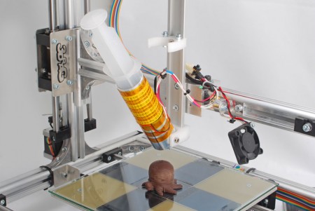
To make the 3Drag printing chocolate objects we have assembled a special extruder (to replace that one used for extruding plastic materials) starting by a very common 60 ml syringe. One NEMA17 stepper motor drives the piston while a heater, to maintain the chocolate contained in the syringe at a temperature of about 32 ÷ 33 ° C, wraps the cylinder.

Chocolate must be melted before being extruded through the syringe needle (that has an internal diameter of 0.9 mm); its fusion is achieved by activating the heater into which is inserted the syringe, without exceeding the threshold of 33 ° C (so keeping the chocolate “tempering”). For this reason, the control board constantly detects the temperature of the heater thanks to a NTC 100 KOhm thermistor installed directly on the body of the aluminum cylindrical heater.
The loss of “tempering” of the chocolate would make impossible to print objects that develop in height, and then the chocolate itself would not be able to solidify at room temperature (24 ÷ 27 ° C).

Milk chocolate and white chocolate need a lower melting temperature to keep the tempering.


See the printer in action:


The chocolate extruder is composed of the following elements:

  • 60 ml syringe for medical use with central needle attack “Luer Lock” which is applied to a standard needle of 1.2 mm diameter (0.9 mm internal), suitably shortened to 33.5 mm;

3DragChoco_007


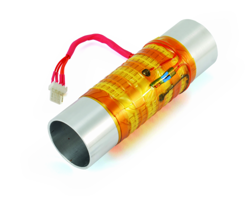
  • Cylindrical aluminum body with outer diameter of 35mm and inner of 31,6 mm, suitably drilled on which is wound a “flat” heating cartridge with a supply voltage of 5 V DC ;

3DragChoco_001


  • Cylindrical aluminum block (on which is fitted a cylindrical heater cartridge 15V / 33W) properly drilled ;

3DragChoco_005


  • Needle sleeve (made ​​from a rod of aluminum) that “keeps warm” the needle of the syringe during printing ;

3DragChoco_002


  • The extruder system so assembled, attaches to the printer structure and is completed by:
  • Aluminum rail IGUS (cod. NS-01-27) from 27x300mm which also represents the backbone of the whole extrusion unit;
  • Skid IGUS (series 27 cod. NW-02-27) which is anchored to the syringe piston through a bracket made ​​of Delrin;
  • Aluminum plate, 4 mm thick, for the fixing the gear wheel;
  • Aluminum angle bracket for mounting the extruder to the arm of the 3Drag printer;
  • M8x190mm threaded rod to drive the syringe piston;
  • 2 ball bearings 8x22x7 mm with dust protection;

3DragChoco_008

  • Supports for the fixing of the heater, the syringe and the motor, gear wheel with 43 ​​teeth (Ø66,2mm) and 10 teeth pinion (Ø 17,6mm) made ​​of Delrin;

3DragChoco_009

  • A NEMA17 2.5A stepper motor, the same used for the extruder for plastic, drives the feeder that pushes on the piston of the syringe. The heating element to be inserted in the cylindrical aluminum block is 15V / 33W, while to coat and heat the cylinder you have to apply the “Flat” heating element coupled with a NTC axial 100 KOhm thermistor.

3DragChoco_012


Assembling the extruder


Once in possession of all the necessary elements you can proceed to the assembly of the various elements of the extruder, as follows:

Before starting, we give you a suggestion: wash with a washing-up liquid and disinfect all the aluminum and plastic elements present in the kit

Insert the cylindrical block in the holed end of the aluminum cylinder (the element could have been already inserted during the fabrication) and align the external holes with the internal ones;

3DragChoco_011

Strip the two glass-fiber sleeves from the heating cartridge wires;

DSC_5065

Halve the two sleeves with the wire cutter; then, insert only two of the four halves of the sleeves on the wires;

DSC_5066

Halve the heating cartridge wires;

DSC_5067

Peel off about 2mm of the two wires bits and tinplate them; Bend as in the picture the two NTC wires and level them even with the wire cutter;

DSC_5069

Solder the two wires to the NTC legs and protect the joint with the glass-fiber sleeves. We will use the NTC so assembled later on;

DSC_5070

Insert the cartridge heater in the cylindrical block after it has been sprinkled with thermal paste, then lock it with a M3 grub screw (check that the latter is not already screwed in its position);

DSC_5072

Insert on one end of the rail (that one with a countersunk hole) the heater Delrin support, align it with the hole on the guide and fix it using a TSE M4x20 screw with lock washer and M4 nut. Note: the aluminum guide must be inserted hard inside the Delrin part. If the operation is difficult, you can use a rubber mallet;

DSC_5075

DSC_5078

5079

Lock the Delrin syringe holder (fourth hole on the rail) with a TSE M4x20 screw, lock washer and M4 nut.

DSC_5082

Slide the skid into the aluminum rail;

DSC_5083

Insert one bearing in the right place on motor support (you can use a vise to fix it);

DSC_5084

Then, insert the Delrin motor support on the free end of the rail, keeping the bearing on external side. Even in this case, if the operation is difficult you can use a rubber mallet;

DSC_5087

Insert to the designed housing on the just assembled support, a M4 washer, nut and TSE M4x20 screw. Lock it tight to fix the support in its position;

DSC_5088

Insert the second bearing in the right slot left on the aluminum plate, as shown in the picture;

3DragChoco_014

Screw in partially the M4x6 nut in its housing on the motor pinion (if not factory inserted), then assemble this one on motor shaft (not included in the kit) and align it with the end of the shaft itself. Lock the nut with the right Allen key, avoiding too much torque (otherwise you can damage the thread);

DSC_5089

Note: you can purchase the NEMA17 2.5A stepper motor separately, from our store (cod. STEPMOT3DRAG) or you can reuse the one originally installed on the printer;

Assemble the stepper motor (leaving the wires as shown in the picture) on its Delrin support by using four TE M3x16 screws. Don’t bind them but simply hand-fixed, to allow the fine positioning of the motor later ;

DSC_5092

Screw partially in the slider holes, near the syringe holder, a M4x20 TCE screw, with M4 nut and lock washer and in the second hole, a M4x10 screw with lock washer;

DSC_5093

Apply on the slider the dedicated Delrin bracket, inserting it on the side. The two washers must stay above the bracket, and the latter must be centered on the slider;

DSC_5097

DSC_5099

Fasten tight, by using the appropriate Allen key, the short screw. Screw the long one as enough to position its head at 12mm from the guide, as shown in picture;

DSC_5100

DSC_5101

Fasten with a 7mm wrench the M4 nut holding the screw with the Allen key; Check that the slider can move smoothly along the rail;

DSC_5102

Insert in the appropriate Delrin bracket housing a M8 self-locking nut;

DSC_5103

Insert a M8 threaded rod in the bearing mounted on motor side and then screw for about 2cm a M8 nut on the side near the slider. Put on the rod a M8 lock washer and a normal washer as seen in the following picture;

DSC_5104

Screw the threaded rod in the M8 self-locking nut, caring that the rod itself is not exceeding the length of the nut (you can turn the rod by using a pinch with a rubber protection not to damage the thread)

DSC_5106

DSC_5105

Holding with a hand the Delrin bracket mounted on the slider, fasten the M8 nut with a 13mm wrench (do not tighten excessively);

DSC_5108

3DragChoco_015

Insert on the threaded rod (engine support side) a 8×16 washer, then the Delrin gear wheel with the hexagonal housing on the external side, as in the picture;

DSC_5109

Insert on the hexagonal housing a M8 nut;

DSC_5110

Then insert the motor into its support after checking the correct coupling between the gears, then lock it by fastening with a 5,5mm wrench the 4 hexagonal head M3 screws;

Insert on the four motor support housings 4 M3x20 TC screws, then insert on each one a M3 normal washer and a lock washer (working as a shim) and last, insert the hexagonal spacer F/F by 20mm. Screw in the spacer just lo lock them in position;

DSC_5112

Fix the aluminum plate (with a bearing) to the spacers using four M3x12 TCE screws and M3 nuts (and lock washers);

DSC_5178

Note: with the four screws fastened tight, the gear wheel must be able to rotate smoothly on its shaft, without oscillating. If not, take care of spacing out the aluminum plate by adding or removing washers between it and the hexagonal spacers. The kit includes 4 additional M3 lock washers;

DSC_5113

Take two M3x20 screws and insert a washer on each, locking it with a nut M3;

DSC_5114

Insert the two screws into the housings on the syringe holder, previously fixed on the aluminum rail, and lock them with a M3 lock washer and a nut, as you can see in the picture;

The two 3×9 washers are needed to lock the syringe in its holder, avoiding its movement (upward) when you are pulling up the piston. So you need to check that the plastic grip of the syringe can fit below those washers;

DSC_5115

If necessary, you can slightly bend upward the two washers through a pinch, to make the syringe insertion easier;

DSC_5117

Fix the aluminum angle bracket to the guide by using two M4 screws with countersunk head;

DSC_5122

Note that the bracket is perfectly square with the rail, otherwise you should loosen the screws and fix it;

DSC_5123

Now you need to apply on the aluminum cylinder (about at 35mm from the lower end) the NTC thermistor (that has the two wires previously soldered) and then secure it with Kapton tape, that can guarantee the fixing properties even at higher temperature (over 40°C);

DSC_5125

DSC_5126

Note: optionally, you can also wind up on the cylinder a “flat” heating element (cod. COM11288), with power voltage of 5V, to guarantee a more uniform heating of the syringe, especially if the printer will operate in cold rooms; In this case, the heating element must be connected in series with the cartridge. Also in this case, to fix it you must use a Kapton narrow tape or similar, that guarantee its properties even at temperature exceeding 40°C; The following picture shows the cylinder complete with the flat heating element;

3DragChoco_020

Fix the full cylinder to its support using two M4x12 screws (wiring toward the rail), with cylindrical head, that must be fastened enough to get a slight friction. Don’t apply excessive torque to avoid damaging the aluminum part;

DSC_5128

Insert the needle in the appropriate “aluminum sleeve”; then insert the syringe into the cylinder;

DSC_5134

DSC_5136

Make sure that the syringe is free to swing front to about 30-45 ° ; see an example with the flat heating cartridge installed on;

3DragChoco_024

Check the right assembly of each part, assuring that the syringe is perfectly locked into its position: to do it, tilt the cylinder to the aluminum rail, align the syringe with its holder then position the piston to insert its end to the appropriate housing on the slider, as in following pictures;

DSC_5139

DSC_5141

Note: check that the plastic structure of the piston is not interfering with the guide and the slider;

Now, get the 3d Printer, cut the plastic clamps that are fixing the wiring to the printer’s structure, near the printing head;

DSC_5143

Unplug the wiring of the heater, the NTC sensor and the printing motor by unsoldering the connections; you can keep the fan connected; write down on a sheet the original connection scheme (i.e. the colors must match). Insert on each wire a heat shrink sleeve (2,5mm diameter, 15mm long), then solder the 2 heater wires to a couple of clips, the 2 coming from the NTC to another couple of clips and the 4 wires for the motor to two couples of the clip, united together (follow the flat cable sequence: blue, green, yellow and orange). To make connections easier, you can apply labels to the wires, to identify quicker the device (NTC, MOT, Heat…);

DSC_5146

The next operation is the removal of the extruder body from the printer arm. The extruder is fixed to a bracket that in its turn is secured to the horizontal arm of the printer using two M5 screws. Before removal make a mark with a pencil on the arm of the printer to identify the original position of the nozzle (ie the center of the bracket that holds the extruder) to allow the correct positioning of the needle of the syringe and in future to allow to reposition the extruder in the correct position;

DSC_5148

Remove the extruder by unscrewing the two screws, as in the picture;

DSC_5149

Loosen also the two fan fixing screws to move it slightly to the right, to allow the installation of the new extruder;

DSC_5150

Insert two square M5 nuts on the upper housing on the printer arm;

DSC_5151

Position the chocolate extruder taking care of aligning the needle with the mark previously done on the guide. Fix the unit to the printer by using two M5x16 cylindrical head screws, one lock washer M5 and 2 normal washers 5×10;

DSC_5153

Make the electrical connections to the machine of the heating element and the extruder NTC having stripped, tinned and grouped with small clamps its cables.
Note: if you use two heating cartridges (the cylindrical one and the “flat”), these must be connected in series with each other and the element thus obtained must be connected to the terminals provided for the heating cartridge;

DSC_5157

Twist each other the 4 wires of the stepper motor then connect them directly to the corresponding terminals, matching the color of the conductors (engine wires -> flat wire cable: Blue with Blue, Red and Green, Green with Yellow, Black with Orange).
Note: If you use a NEMA17 motor, whose wires were shortened (such as the one recovered from the printer standard extruder), to reach the terminals is necessary to extend its wires through the piece of 4-way flat cable included in the kit. In this case, it is recommended to be very careful so as not to reverse the connections causing damage to the driver. Group the motor cables with clamps.

DSC_5159

Fix the cables to the bracket, using the spare clamps;

DSC_5163

After completing the cabling, you should have a printer like the one shown in the picture;

DSC_5168

DSC_5172

DSC_5173

Set the limit switch of the Z axis so that after the HOME command, the syringe needle result lifted from the plate by about 1mm. If the adjustment of the stop screw is not sufficient, change the position of the arm relative to the carriage of the Z axis by loosening the fixing screws.

Apply sewing machine oil on the extruder threaded rod while on the gear wheel and pinion spray a bit of silicone lubricant.

The mechanical modifications to the printer end here. To operate in the best hygienic conditions, it is recommended to install on the printing plate an appropriate glass.
Before use, you should clean and disinfect thoroughly the needle, the aluminum needle cover and all that could come in contact with the chocolate. 

In order to use the printer as 3Drag for chocolate you must also update the firmware of the electronic board.

The firmware “Marlin V1 (LCD ON, Choco ON)” can be downloaded directly from here. Besides, you must set the right printing parameters.

Obviously, the firmware can be changed to your preference every time you wish, depending on the extruder mounted on the printer.


Firmware modifications to print with Chocolate

To operate with chocolate it is necessary allowing the heater to reach much lower temperature than that usually used with plastics. We must remember that the Marlin firmware comes for the control of FDM 3D printers using plastic filament and includes a whole series of protections including that one which prevents to extrude the material below 170 ° C. Having to melt the chocolate at a temperature of about 33 ° C we have to change the statement:

#define EXTRUDE_MINTEMP 170

Into:

#define EXTRUDE_MINTEMP 10

This change moves the protection threshold from 170 ° C to 10 ° C.


Another necessary firmware change concerns the steps/mm of the extruder motor, because of its different mechanic conformation. The instruction to modify is:

#define DEFAULT_AXIS_STEPS_PER_UNIT   {64.25, 64.25, 2560, 600}

The last parameter (600) indicates the rotation speed of the motor.

To obtain a right extrusion speed, allowing thus fluid extrusion of chocolate, this value must be reduced by 10 times so the correct instruction will become:

#define DEFAULT_AXIS_STEPS_PER_UNIT   {64.25, 64.25, 2560, 60}
Another change relates to the PID that controls the temperature: to prevent excessive fluctuations, we modify the parameter P:

#define DEFAULT_Kp 22.2

Becomes

#define DEFAULT_Kp 32.2

This value has been calculated empirically but gave great results on real printing.


From STL to chocolate object

As already mentioned at the beginning of this post, we must remember that the cooling time of chocolate layers is much longer than that used when printing with plastic. We therefore recommend a printing speed of maximum 20 mm / sec to have individual layers of chocolate cooling down properly.
In the Slicer parameters, we must set the nozzle diameter to 0.9 mm (you can also set it to 0.8mm to “cheat” the slicer and then make higher definition prints), the layer height to 0.7mm and the extruder temperature not exceeding 35 ° C (if you are using dark chocolate; with different kinds, the threshold is lower).
As for the 3D prints with plastic, it will take several tries to get the best results.

The configuration parameters also depend on the shape of the object, the type and quality of the chocolate used and the ambient temperature environment in which the printer operates.
Therefore, the determination of the parameters is the result of personal experience gradually gained into this field.

In any case, printing objects with tiny x-y dimensions and high z slows down the cooling process of the chocolate. So it could be necessary to direct a cold air flow to the object (you can do it through a small Peltier cells system, not included in the kit) to speed up the chocolate cooling on the top layers, to avoid the risk of structure collapse.


Preparing the chocolate in the syringe

Before starting with the printing you must turn on the printer well in advance and activate the heater to allow the cylinder to reach the required temperature (normally set at 34 ° C for dark chocolate). Then fill the syringe with the melted chocolate, the temperature of which should not exceed 33 ° C (for dark chocolate). Alternatively you can put the dark chocolate chips that can be dissolved by soaking in hot water (<33 ° C) the syringe enclosed in a hermetically sealed bag. After expelling any air bubbles and having applied the needle, insert the syringe into the cylinder by hooking correctly the relative rod to the driving system. Operate (by software command) the extrusion of a few cm of chocolate and then start printing.

Note: If you print objects of chocolate on slices of bread, cookies or other items that are not only the glass plate, you need to adjust the limit switch of the Z axis so that the reference plane for the HOME of the axis coincides with the new reference surface by manually adjusting, if necessary, the height of the extruder by acting on the threaded bar of the Z axis.

Finished the available chocolate, remove the syringe from the extruder (with one hand hold the aluminum rail and with the other pull towards you the piston rod to remove it from its housing). During extraction, make sure not to accidentally let fall the needle cover to prevent damage.
Note: To avoid deforming the aluminum rail, stop the extrusion as soon as the syringe piston has reached the lower limit .

To resume work, fully retract the push-rod skid, reactivate the heater, reinsert the syringe filled with chocolate and repeat the above steps.


Learning how to use the RandA Board

$
0
0

It is time to use the board that combines the capabilities of Raspberry Pi to Arduino ease of use.

Raspberry Pi and Arduino worlds got close but they did not collide: indeed, they have resulted in a cooperation that has created a hybrid of enormous potential. We started talking about it in this post, where we presented the board RandA (the name means Raspberry and Arduino), a prototyping board whose core is Arduino and can be interfaced to the expansion connector of Raspberry Pi (also the last version) and hosts the classic female strip to connect Arduino shields.
In the RandA: Merging Raspberry Pi and Arduino" href="http://www.open-electronics.org/randa-merging-raspberry-pi-and-arduino/">previous post we saw the main features of this collaboration between Raspberry Pi and Arduino and now we will analyze some aspects with concrete examples. We will take for granted the successful installation of the software supplied with RandA, which includes the modified Arduino IDE to be used on your computer and all the software on Raspberry. For this installation, please refer to the previous article and especially the README files in the RandA/releases" target="_blank">distribution.

RandAFEA


As we have seen, the RandA system allows two approaches for its programming and usage: an Arduino-centric approach, where Arduino is to “lead the dance”, and a Raspberry-centric approach, where instead the reference environment is the Linux operating system.


Arduino-centric approach

We start with the Arduino-centric approach and begin to develop a sketch on our computer using the modified Arduino IDE. The IDE is perfectly compatible with the traditional use of Arduino connected locally to the USB port of your computer. So, for now, there is nothing to add for those who have already used this programming environment.
The surprise comes when we select the port where Arduino is connected, among those available. Along with any local ports (serial and USB simulated serial), there’s a new port described by a complex name that contains a network address. For example:
//192.168.10/Arduino
This, of course, if the RandA system is on and is networked via the Ethernet port, available on Raspberry, or by a WiFi dongle, also connected to Raspberry.
You may have several ports in the list, if there were more RandA networked. So we could load sketches on different systems.

Fig2

Also, if we had not permanently assigned from the router a static local network address for RandA, we could use this modified IDE to detect the addresses assigned by the router; then we connect with an SSH client as MobaXterm or via the browser to the web server installed on RandA.
For a first test we can run a sketch used on Arduino, or one of the examples listed in the IDE. Once you select the remote port and finish the upload, the sketch will work as usual. For example if we had used the sketch “for blinking”, we could see the flashing LED on RandA. Remember that RandA is fully compatible with Arduino Uno.
But what if we would upload a sketch that uses the serial port? No fear, activating the IDE console as usual, we will get the data stream as if we were locally connected to Arduino. In fact, in RandA, the serial port was completely remotized. So we can fully interact with Arduino.
So far we have found that, without having to use specific shield, Arduino is connected to the network relying on Raspberry networking. Also, you can upload sketches, that is not possible using network shields. Although this is already a good result, it is only a small part of RandA potential.
To RandA we can connect one of the many available shields for Arduino, to manage or expand I/O connections: I / O expanders, relay systems, opto-isolated systems, motor drivers etc.
But you can do much more and overcome, in part, the hardware limitations of Arduino. In fact, you can think of using Raspberry to perform some tasks. To do this it is necessary that Arduino can run commands on Raspberry and possibly read their response.
For this purpose, it has been prepared a library included on modified Arduino IDE. This library (RAComm) provides the ability to run commands on Raspberry and receive the response, but also allows you to open a file (read/write).
While talking with Raspberry, Arduino commits the serial port: this is not available for the dialogue with the IDE, so you cannot use the IDE console. For this reason it has been granted the possibility to open a console on Raspberry to write messages, to read input or simply for debugging. But this console, X terminal like, needs a connection with Raspberry (networking with SSH or directed by terminal) to be visible.
Let us show you an example of this synergy between Arduino and Raspberry: we use a useful Linux command that allows you to make a request (GET) of a resource on the network, the command “curl”.
Let’s use it to request to the site “openweathermap.org” atmospheric data relating to a location. Following the directions of the site, we know that the request must be made in the format shown in Figure, where there also appears the reply. In the example we used Rome but the request can be made for any location worldwide.


Fig3

In basic mode, the data is provided in JSON format; but you may also have the XML.
The sketch, which is provided as an example in the library, it’s called “ReadWeb” and would be made up of a few lines of code unless for the part about the extraction of data from the wordy text returned from site. In fact, in addition to the code to manage the HTTP protocol, also the data replied are numerous. At this point we must keep in mind the memory limitation of Arduino. In fact, it is unthinkable to store the whole response in a buffer; furthermore the buffer of the serial is 64 bytes and it is not advisable to read more data to avoid data loss. So we have to get the response in small pieces and scan character by character to detect the beginning of the data that we want to extract.

Fig5a

Fig5b

These figures show the essential parts of the sketch. As we see, the request is made “once”, and to repeat it you must reset Arduino. In fact, this sketch is demonstrative, while for a real use, probably, would be necessary to repeat the request at regular intervals. To do this, just add another command to set the alarm and then a “shutdown” command. That is, for example, to read the meteorological data every hour, just enter:

- RAComm.sendCommand(“SetRestartAt -sd 00”)

- RAComm.sendCommand(“sudo shutdown -h now”) 

The first sets the alarm at next round hour, while the latter causes the system shutdown. (Remenber that in RandA “shutdown -h” commands the power off at the end of the closing process).

Also, the sketch writes to a file any response creating a sort of log. To do this you use library functions that allow you to open a file (only one at a time!), write or read it. The controls used in the example are:

  • RAComm.openFileWrite(“home/pi/weather.log”)
  • RAComm.writeRec(rbuff)


The file is automatically closed by the closing command of the communication with Raspberry (even if there is a specialized command).
The data extracted from the response are visible in figure. For the temperature, we convert it from the absolute temperature to Celsius degrees (T absolute-273,15).

Fig6

The data is saved to the file. But for an effective use it could be used, for example, to activate or adjust a heating or cooling system by means of the Arduino digital or analog outputs.
As mentioned, the biggest part of the sketch is related to a problem that does not affect the interaction Arduino-Raspberry, but rather to overcome the RAM limitations of Arduino. The answer is split into records of up to 64 characters, but the pattern to be detected (for example ” temp ‘:’) could be split on two lines. Although the issue does not directly affect this article, we give a brief description of the algorithm adopted.
The issue has been generalized and then you can use it on other occasions to read a HTML text looking for particular patterns, in a logic: key-value.
First, we defined a structure “pattern” and an array of these. Each element of the array contains the pattern to be searched that works as a start of the data to be read and a character indicating the end. Also there are defined some variables used by the algorithm. The algorithm works by comparing in parallel all the defined patterns, by scanning the single characters. When it finds a pattern, begins to read the data independently from the other pattern. The data is stored (as strings) in a buffer of corresponding structure.

Before moving to another RAComm library example, it is the case to clarify which commands can be entered in RAComm.sendCommand (): all of them! The standard commands from Linux distributions (Raspbian), all the programs that we have provided for RandA and any script or executable that you can implement. We have already seen the use of a set command for RandA: SetRestartAt (is an executable in C), and now is the chance to briefly list them all; you can see them in Table 1, but they can also be listed from the Raspberry Pi console typing “commands”. Adding -h also displays all the help. Some of these, indeed, as ArduLoad, Arduio and ArduInterrupt, are designed for Raspberry-centric usage, as they provide access to features Arduino by Linux script.

COMMAND               MEANING
ArduIO Define, read and write Arduino pins
Arduload Loads a compiled sketch .hex saved on Raspberry
ArduInterrupt Waits until an interrupt on an Arduino pin
ResetRandA Arduino Reset
GetRTC Reads RandA clock
SetRTC Sets RandA clock
SetRestartAt Set the restart alarm
ResetAlarm Resets alarm
SetSysClock Sets the system clock from the RTC
SendMail Sends an email


The second example explains the delivery of an email. Suppose we want to detect the presence of an important signal and alert someone of the event accordingly. The detection of the condition is typically a task for Arduino. For example, we could detect the overpassing of an analog threshold or an ON / OFF condition. Sending an e-mail, however, is a daunting task for Arduino mainly because of the SMTP servers that are now using secure protocols, impossible to implement with Arduino. The command to use could be for example:

RAComm.sendCommand(“
SendMail mailto=\”pippo@pluto.it\”
subject=\”Rilevazione\”
filemess=\”/home/pi/messaggio.txt\” “)

The command has been split across multiple lines only for convenience of printing. While the pattern \” indicates the presence of double quotes within a string (the command to be passed as an argument to the function). “SendMail” taking it from the file where it was placed automatically formats the message text.
The command provides the possibility of also simply sending a short text, instead of the text stored on a file, in this way:

RAComm.sendCommand(“
SendMail mailto=\”pippo@pluto.it\”
subject=\”Rilevazione\”
message=\”Valore : 320\” “)

You can also add an attachment or more recipients. But for more details, please refer to the command help.

At this point it is the case, however, indicate that it is necessary to initialize the file

“/home/pi/bin/Mail.properties”

with its own data, so with the user name and password recognized by the SMTP server and the address of the server itself. Moreover, one must keep in mind that those not used to a mail client (like Outlook or Thunderbird) could have the Gmail server not set to receive external commands, so the proper configuration must be done on Gmail settings.
In the example included in the library, called “SendMail”, it is periodically detected an analog value and along with the timestamp taken from RTC it is stored on a file and then sent to an e-mail address.
It is not sent only the last value read but rather the last 5 records. To do this you use the Linux command “tail” that extracts the last n records from a file.

Fig7

With these examples shown, the potential of the link library with Raspberry should be obvious. Keep in mind also that in case of logical error (for example a sketch that will shutdown the system at its very power on), you can disable the communication with Raspberry by opening jumper JP1 which is managed to report to Raspberry the intention to communicate.

The script that listens signal is launched at startup (in /etc/rc.local) and is called StartListenCmd. It can also be launched with a log file. But more simply, in case of serious problems of debugging, you can directly launch the C program that manages the communication, called ExecSCmd (after disabling StartListenCmd). ExecSCmd can be launched with the debug flag -s to echo on the console all that passes on the serial. The sourcecode ExecSCmd is located along with the other program sources for RandA in:
“/ Home / pi / workspace / cworkspace”
There is still a further opportunity to exploit Arduino-centric approach: you can always keep powered Arduino acting on the jumper switch SW2 separating Arduino from electronic switch management.
Arduino deprived of its linear power supply and USB needs very little power and it can also put itself in a very low power consumption state.
In this state Arduino can turn Raspberry on giving a pulse to its D4 pin (if the corresponding jumper JP2 is closed). A further example in this library shows this use, and turns Raspberry on if its analog input A0 reads a value greater than 300.


Raspberry-centric approach 

Those familiar with the Linux operating system will definitely find it easier to use Raspberry as a programming base. For this purpose you can use a powerful C development environment like “codeblocks” that we installed on Raspberry, or the Python language for which we have installed the development environment “idle”. Because on Raspberry is installed Java you can also use this powerful language. In fact there are already Java programs used in RandA, as the SendMail command or servlets in the WEB server which will be discussed later. We have not installed a development environment for Java yet since we are not satisfied by the free IDEs available for a reduced hardware as Raspberry. Although installable from Debian package repository, Eclipse is not in a satisfactory version both for installation problems and for performance problems.
Java programs complete with source code are categorized into:

“/ Home / pi / workspace / jworkspace”
The programs (or scripts) can also be made in Arduino-centric approach as we have already seen.
You can use the serial port to communicate with sketches dedicated to manage the communication (ie outside the library RAComm). In this way Arduino becomes a powerful programmable  for Raspberry.

The command “Arduload”, (accepting as argument the full executable file name (.hex) with the complete path), allows you to change from time to time the behavior of Arduino, because it “installs” on Arduino the sketches used by the application. These sketches, in executable file format, can be created with the remote IDE or with the IDE installed locally on Raspberry. In fact, both versions of the IDE, besides managing the upload of the sketch, save the executables on Raspberry in two separate directories:
✦ / home / ArduinoUpload: for sketches processed locally
✦ / home / RArduinoUploads: for sketches processed remotely

This is a further addition we have made to the modified IDE.
As an example of application that uses Arduino as a device, just refer to the command “ArduIO” already listed in Table 1. This C program can be found also in the “cworkspace”, along with its source code.
ArduIO wants to be the equivalent of the utility GPIO (wiringPi) of Raspberry. It lets you manage the Arduino pin from the command line. For example, to turn on the standard Arduino LED (pin 13) you must:

  1. Define as output pin 13: ArduIO -set 13 out
  2. Write 1 to pin 13: ArduIO -wrd 13 1

To turn it off, type: ArduIO -wrd 13 0.
You can use the usual approach used with Arduino: read analog and digital pin, enable / disable digital output and adjust the PWM pins. Typing “ArduIO -h” you get the detailed help. More precisely, in Table 2 we listed the various options.


OPTION           MEANING
-set n x Set pin “n” as x=inp,out,ipl (ipl:input-pullup)
-rda n Read analog pin n
-rdd n Read digital pin n
-wra n v Set pin PWM
-wrd n v Set pin digital (0/1)(NB: remove the jumper before setting pin 4, since it is connected to ON/OFF switch)
-pou n v Pulse on pin n with frequency v (tone)
-poi n v Read pulse duration on pin n(v=0/1 defines input high or low)


The program uses a sketch (SerialRasp) to which it sends the corresponding commands, and it is the latter that activates the pins. So this sketch must have been previously uploaded to Arduino. But ArduIO overcomes this problem by loading it automatically if it is not present on the Arduino. To allow this it is necessary:

a) that can identify the sketches present on Arduino,
b) that can find the sketch in a predetermined position in case it was not the one established and needs to uploading

The first point is easily solved by preparing the sketches so that if polled they respond with their own name; while for the second item it has been prepared a directory “/ home / pi / bin / sketch4cmd” from where take it. Figure has highlighted the collaboration between the two environments with particular reference to the recognition of the sketch and to its automatic uploading.

Fig8

It is not really necessary to use compiled languages ​​like C, to build Raspberry applications that use Arduino for input / output. You can also use bash script (Linux) or Python script. Just use the commands prepared for RandA (Table 1) to simplify the task. The next example shows a small demo application that reads the value of the voltage present on pin A1 (for example, supplied by a photocell) and activates the standard Arduino LED when the read value is lower than a threshold.

Fig9a

Fig9b

Of course, the script is mostly educational, but with small additions you can insert a periodic cycle or you can place a timer check or sending an e-mail alert.
These two files (ScriptExample4IO.sh and PyExample4IO.py) are present in the directory / home / pi / bin / examples.
There is an additional command that allows Raspberry to use the full potential of Arduino and that can be used in scripts: ArduInterrupt.
This program uses the sketch “SerialStop”, present in “/ home / pi / bin / sketch4cmd”, and essentially waits until a certain condition is met. The condition may be on a digital pin, when it becomes 1 or becomes 0, or on an analog pin when the measured value is greater or less than a certain threshold.
For example, “ArduInterrupt -ana 2 lt 200″, freezes until the analog pin 2 of the Arduino value drops below 200. It ‘clear that the use of this command is within a script where subsequent instructions trigger an action. Also the script will be probably launched in background.
How to develop applications on Raspberry efficiently? With the Arduino-centric approach we used a remote location (any PC connected to a local network) to develop sketches that could also use the potential of Raspberry. Now changing the point of view it is still possible to use a remote desk (always our PC connected to a local network), this time using a remote console on Linux SSH protocol, but with the additional option of a graphical environment. For this you can use a software that allows you to act as X Window terminal (which is the graphical environment based on Linux). One of these is MobaXterm (free and downloadable from the website http://mobaxterm.mobatek.net/).
In Fig. 10 there is shown a typical situation in which along with the console MobaXterm, are superimposed a window on the file system and a codeblocks IDE window for C programming.

Fig10

Who is more used to Linux or other modern operating systems, prefers this Raspberry-centric approach, because it allows a more flexible and efficient use of RandA. Those who are more accustomed to Arduino style, will prefer the former approach. In fact it is also useful to mix the two points of view depending on the application. But above all, we believe RandA is an ideal system for teaching and first approaching to programming and to digital systems, because you can cover, with it, an incredible amount of topics and operating environments.


Web Server

The supplied software is not limited to what we just described. In fact, we decided to add a Web server. This Web server allows a basic system management in a wide area network. In fact, until now we have limited the use of remote access exclusively to the local network both for the network software used and for safety reasons. With a Web server, it is possible to overcome this limitation simply configuring a proper port-forwarding rule on the router to have a network address visible outside.

The software server used is not just a Web server, but a “Web Application Server.” This mode uses an approach more “interaction-oriented”. The server is based on one of the most popular free software: Tomcat. Unfortunately, a software of this kind involves the use of Java Servlet (or JSP script) for interactive applications. But the complexity of the software is repaid by the remarkable efficiency of the applications; just think that all servers use these types of professional environment or its competitor “dot-net”.

But if you are new to Servlet or JSP, no fear, because the server was prepared to handle even CGI scripts; i.e. Linux or Python script. This way you can build your interactive applications and use them by a browser anywhere in the world.

Tomcat is installed (version 7) in: “/home/apache-tomcat-7.0.47″

In this directory there are two scripts: startWebS.sh and stopWebS.sh, to start and stop the web server. The first is called within the file system startup “/etc/rc.local”. If you want to disable the automatic web server start just comment this command in that system file.

The Tomcat is listening on port 80 (instead of 8080) by updating the file: “/home/apache-tomcat-7.0.47/conf/server.xml”.

Within the Tomcat directory you can find all the web server related files: from applications to static pages. In particular, the directory “… /webapps/ROOT” contains the starting page “index.html”. While the application for the management of Raspberry and Arduino is all contained in the directory “… /webapps/RandA”.

For those who want to load their own or third-party applications, the easiest thing to do is to use the archive file .war (as usually are deployed Java web applications) and install them through the easy Tomcat manager console. This console is accessed at “http: //…../manager” and is protected by user name (default Tomcat) and password (default Tomcat). The .war file can also reside on the computer connected to the web server. In fact, the console allows to automatically downloading and installing at once. So essentially the applications installation is remotized.

Those who wish to use simple HTML pages can place them in the directory where ROOT will be immediately available. Obviously can also create subdirectories of ROOT.

Instead when using the CGI mode, bash scripts should be placed in the directory:

“/home/apache-tomcat-7.0.47/webapps/ROOT/WEB-INF/cgi”


But, be careful, they must be referenced as: http: //…../bin-cgi/nomedellloscript

Example: http://192.168.1.8/bin-cgi/testcgi2.sh

The file “testcgi.sh” and “testcgi2.sh” in the directory “../ ROOT / WEB-INF / cgi”, are two sample files that show the use of simple bash script for Web dialog and launch Linux commands.

In case you want to use a different script interpreter, you have to edit the file “/home/apache-tomcat-7.0.47/conf/web.xml” (block <servlet> parameter “executable”).

The start page (to display it in the browser just enter the IP address of RandA), gives access to the management application and to a Web console (temporary) to access Linux also from wide area network (third-party application) .

The management application is currently not password protected, but you can easily change it by editing the file “/home/apache-tomcat-7.0.47/webapps/RandA/WEB-INF/web.xml”, and removing the comment to block authentication. While the Web console has the account “user-name, password”: “RandA, RandA

The management application gives access to the following pages / applications:

✦ Loading sketches on Arduino.

✦ Arduino Console.

✦ Arduino I / O Management.

✦ Defining the alarm.

✦ Clock Adjustment.

✦ Deactivating RandA.


The applications listed above allow you to have remote access to RandA system also by geographical network, but the server has been installed by thinking especially as a basis for customization by users, presumably using a CGI script.


Conclusions

We have tried to provide a system up and running, available to be used in applications of various kinds, also with the addition of specialized hardware. But we wanted to keep an educational point of view, commenting as much as possible the software product, to facilitate customization and improvements.


Arietta G25 – The latest Embedded Linux Board

$
0
0


If you have “broken the ice” with GNU / Linux through Raspberry Pi already, here is a board that allows you to jump into the real professional world, with all the needed support and with totally “Open” instruments and, why not, in an enjoyable way. Arietta G25 is the “mascot” of a series of professional boards designed and made in Italy by Acme Systems. That also provides support to its boards for the next 5 years.

Arietta G25 condenses into a few low-cost square inches many years of experience in embedded GNU / Linux, concretized in the manufacturing of professional systems currently distributed over thousands of units.

The technical features we will describe below are definitely innovative for a board of this size. Besides, the technical level of the board design and the software approach is so high that assigns to Arietta an important role in the professional use of embedded GNU / Linux, allowing customizing and optimizing the GNU / Linux kernel on our project requirements.

“Factotum” Kernel such as Raspberry Pi, full of plug and play drivers and modules simplifies the management for most peripherals, but generates a heavy distribution, both in terms of memory usage and performance. In our case, we can keep the kernel as “lean” as possible, saving memory and CPU cycles while maintaining respectable performance. This also for the benefit of a limited energy consumption, making it possible to use a battery to feed the whole board.

 
The board is equipped with a 40-pin configurable GPIO I/O. In addition to the standard digital I/O, there are several pins that can be configured either as generic digital I/O or as analog ADC and PWM inputs/outputs, as well as I2C, SPI, I2S and UART. The engineers of ACME Systems wanted to add value to their offering with a website full of information and tutorials for users of their boards. In particular, there is an application to configure the different pins and automatically generate the file .dtb (Device Tree Blob) used to bind the desired functions to the corresponding physical pin. The .dtb file is read by the kernel at boot time for the initial system configuration, associating the SoC pins of the physical GPIO pins, and loads their drivers.
There are instructions on the website on how to recompile the kernel to include specific drivers, but also to use precompiled images directly.


Arietta G25 Features

fIG01

We can see the layout of the board with the indication of the connectors and the main and additional components.  

Let us see the main features:

  • CPU Atmel AT91SAM9G25 SoC (ARM9 a 400Mhz)
  • Ram DDR2 available in two versions, 128 or 256 MByte
  • Power feed: single plug, 3.3 Volt DC
  • Digital Levels: TTL 3.3V (doesn’t support the 5V level)
  • PCB layers: 8
  • Supported for at least 5 years
  • Designed and manufactured in Italy
  • Connector J4 – Designed to host a connector with two rows of 20 pins 2.54mm spaced (100 mils). In some cases, more functions are configurable on the same pins through the web-guided process, using the file “acme-arietta.dtb” that is in the root partition.

fIG2

Consequently, the functions described below are not all available at the same time:

  • 1 USB host
  • 1 hi-speed USB host (shares the lines with microUSB port)
  • 1 hi-speed USB host (shares the WiFi adapter lines)
  • 3 lines UART
  • SPI bus: 1 bus with the ability to select up to 3 chips (5 to 50 MHz)
  • four lines:
  • 4-channel ADC with 10-bit resolution (1024 “steps”)
  • audio interface SSC / I2S
  • There are no video outputs or to TFT display, but you can use the SPI bus for small TFT display and the I2C bus for small alphanumeric LCD
  • There isn’t a LAN interface directly but the USB ports can be used to connect a USB2LAN
  • Connector DP – Prepared to host a 6-pin male connector of 2.54mm (100 mils) to connect the USB / Serial DPI converter (Debug Port Interface)
  • Connector WiFi – Ready to host a female connector, 7-pin 2mm pitch to connect the IEE802.11 WiFi b / g / n adapter;
  • Slot for Micro SD board (up to 64GB capacity) with the GNU / Linux distribution (bootable)
  • Connector microUSB to connect the Arietta G25 to PC and access the system. The port is managed like an USB2LAN emulator (USB gadgets)
  • LED configurable by the user
  • Button configurable by the user


Software features


Documentation and Tools

  • Micro SD board with preinstalled GNU/Linux, on sell in the Acme eShop; you can also download the software images for free from Acme binary repository to flash them directly on your microSD boards.
  • Step by step guides to compile your own distribution starting from source code
  • Open source firmware, free software IDE and toolchain
  • Tutorials and code sketches available for free
  • Thousands of Open Source packages you can find on Debian Wheezy repository


Let us prepare the Arietta G25 board 

For the first use, we recommend to use the board with his WiFi adapter and the FTDI converter to access to the console. Those two tiny devices can be soldered directly on the board or mounted on a 7mm female stripe, 2mm spacing for the WiFi and on a 6mm male, 2,54mm spacing for the serial interface.

DSC_4004


We have chosen the WiFi adapter with the external antenna connector. We assemble the pigtail cable and the antenna on the module, and then we plug both modules on their connectors. If we do not think of using any GPIO pin, the board is ready. Now we need to power the board and connect to it for the customizations.

In this case there are several possibilities. You can connect via “serial console”, or connect via micro USB “Device Port”, in which case the board is “seen” as a LAN adapter. We can connect to WiFi using the extension module that we mentioned or finally using a wired Ethernet cabling to GPIO a USB port and using a LAN adapter / USB.
For a first “exploratory” use we still have several possibilities. To begin, let us connect the mini USB cable to DPI serial module. Open a PuTTY terminal on our PC and configure it as shown.

We configure the field “Connection type” to “Serial”. In Serial line, insert the COM port number assigned to the DPI converter. We set “Speed” to “115200”.

 Fig_004


This opens the serial communication, currently inactive. Let’s take a couple of returns and we will see red LED flashing on the DPI module. Now connect the Micro USB cable to the micro USB connector “Device Port” and the other side to another USB port on the PC. Arietta G25 will start on boot, and we can see the messages in console.

Fig_006


Meanwhile, being the first time that we connect Arietta G25 via USB, the RNDIS / Ethernet Gadget drivers will be installed for the adapter. If you use a PC with XP or however the driver is not retrieved automatically, you can download it from address

http://www.driverscape.com/download/rndis-ethernet-gadget

Choose the correct version for your system. Unzip in a folder specially created and run the driver update pointing to the newly created folder. At the end, if you go to Settings >> Network Connections, you’ll see a new LAN connection. Click with the right mouse button on the new tab and select “Properties” from the drop down menu. Here you set the adapter’s IP address and subnet mask with the following values: 

IP 192.168.10.20

Subnet Mask: 255.255.255.0 

Fig_009


Give all the necessary confirmations and close. Open a browser and type the address 192.168.20.10, which is the default address of the board. You will see the page to confirm that everything is working fine. This page confirms that on the board is activated a web server “lighttpd”, a “light” version of the web server and there are a couple of interesting applications: “Codiad Web IDE” and “Linux Command Prompt”. The applications are accessible from the home page just opened. The userid and password to be used are indicated in the page itself. As easy as that.

Fig_010


The first is an IDE for development and management of multi language projects that will be very useful in our implementations. To access it, click on the blue button “Codiad Web IDE.” On the next page we insert given userid and password to get the page. As we see, the structure is typical of an IDE. In the upper left corner, the Explore window allows you to browse files and folders that belong to the www folder. The frame at the bottom left allows us to manage projects, while the large window on the right allows editing code. You can highlight the syntax of code by setting the correct language, by selecting it in the rich list that opens by clicking on the
“language tab” in the contextual menu bar at the bottom. You can split the window into different sections and the merge content between two windows.


Fig_011


The second application is a remote terminal via the web. You must sign in with the general user, “acme” in our case. Once inside we have a terminal window useable remotely. As an example, we gave the command that allows us to verify the occupation of partitions:

df –h

The thing is not accidental. The characters “-” and “+” must not be typed using the normal keyboard but the numeric keypad, or, if you use a laptop as it is in our case, obtained with the key combinations that emulate the numeric keypad. In our case simultaneously pressing the “Fn” and “-” associated with the matrix “Fn”. To use the user “root” you must type the command “superuser”

su

and then type root password (“acmesystems”).

Fig_012


These two applications allow us to handle almost the entire board remotely. We continue to analyze the different possibilities to connect the board, via SSH server and via serial console with the module DPI. We check the presence and operation of the SSH server with the command 

service ssh status 

The response confirms that the server is installed in the default configuration and is activated at boot. We connect using the remote terminal “PuTTY” and the remote File Manager application “WinSCP”. The operating system is virtually the same used with Raspberry Pi. To connect with both applications use the board address 192.168.10.10. We execute the login with userid and password and get visible results.


Fig_013

Fig_014


We take advantage of file manager to anticipate a topic that will be essential for the next configurations and customizations. We go to the folder / boot that “points” to the boot partition, and is mounted automatically at boot and let us verify its content.

Fig_015


Two files are particularly important. The zImage is the image file of the Linux kernel. It is the result of any compilation processes to customize the configuration of operating system according to our needs. In the website of Acme Systems are available pre-compiled kernel for specific requirements, as if we would enable the analog to digital converter. The file “acme-arietta.dtb” contains the pin configuration obtained from the “web” configurator.
Now let’s go back a moment to the terminal emulator connected to the serial “console”. We can use this window as a window terminal, with some limitations that we will see case by case. The main use of the console is to display all the messages output at boot and shutdown of the system. After login with userid “root” and password “acmesystems” try to give a command:

reboot 

You will see that the console does not disconnect, as do the connections via the SSH server. To see the boot messages from the start, just make the connection before powering the board from the micro USB connector. Now we explore the management of GPIO. To know the meaning of the GPIO pins of Arietta G525 the best tool is the Web configurator.

Fig_016


In the basic version we see the default configuration of the GPIO pins. By clicking on any of the pin at the top right of the page we see the description of the pin function. For some pins, instructions to access, read and modify the content of pin are also given. If we want to customize the pin configuration we can use the configuration section on the right of GPIO representation, under the pin configuration. The configuration is done by selecting with a check mark the functions you want to enable. If you do some test, you can verify that some functions share the same pin as ADC and PWM, that share pin 34. 36, 38 and 40. Therefore, we can choose only one of the options, mixed configuration of these pins will not be accepted. Another case is the I2S bus, which requires the simultaneous activation of the I2C bus. In our case, we opted to activate the bus i2c-0 and the ADC.

Fig_017


Obtained the configuration we want, we request the preparation of the customized file .dtb by clicking on the button “Generate acme-arietta.dtb”. After creating the file is being proposed a link to download the file on your PC. Now we invite you to check the “Tutorial” site to see if additional steps are necessary. In the subsection “Using the A / D converter lines” we find a surprise. In the Linux image distributed with Arietta G25 is not present the driver Atmel ADC so it must be enabled using the “menuconfig” (see appendix to the book mentioned) and recompile the Kernel. Fortunately in the tutorial there is provided a link to download a pre-compiled kernel that includes the required driver. We download it to a folder on your PC. Now we have to update the boot partition of our board with the two files we downloaded. We decided to use the tool WinSCP that allows us to move and swap files between the board file system and PC.

Fig_018 

First we create a backup folder on your PC, move the original files zImage and acme-arietta.dtb to the backup folder. We mount in acme-arietta.dtb the configuration file that we downloaded from the Web configurator. Move the zImage and acme-arietta.dtb to the boot folder. Well check the file names and their presence in the folder. Now we go to the console window and type the command:

reboot

Once completed the boot process, reconnect the Terminal Putty window and check the functioning of ADC converter giving the following command:


root@arietta:~# cat /sys/bus/iio/devices/iio\:device0/in_voltage0_raw

1023

root@arietta:~# cat /sys/bus/iio/devices/iio\:device0/in_voltage1_raw

1022

root@arietta:~# cat /sys/bus/iio/devices/iio\:device0/in_voltage2_raw

1001

root@arietta:~# cat /sys/bus/iio/devices/iio\:device0/in_voltage3_raw

1017

root@arietta:~#


Fig_019


We can also connect a trimmer 4,7KOhm and try to acquire the digital values at different positions of the trimmer cursor, obviously using the command corresponding to the channel ADC to which we connected the trimmer, the first in our case. We should always remember not to exceed 3.3V input to each pin, otherwise we will destroy the board. The inputs of the SoC AT91 DO NOT tolerate voltages above 3.3V.

Fig_20_old


We see now that we have activated the I2C bus. As a first test of his presence we’re going to verify the presence of the device files in /dev. Effectively we find the file i2c-0, indicating that the configuration operation is successful.


Fig_021


To manage and control at best the I2C bus we should install the i2c-tools package, which is part of the repository of the distribution. To do this we must connect the board Arietta G25 to Internet. At the moment we can use wireless WiFi. We have already connected the module to the board, so we just have to configure the file / etc / network / interfaces to work with our network. In figure is visible a FACSIMILE file. In fact the essential parameters to configure are those for the SSID, type of protection and password. For a connection with WPA you can use the example shown, of course entering the parameters related to your network. For a connection with WPA you can use the following example:


auto wlan0

allow-hotplug wlan0

iface wlan0 inet dhcp

#  wpa-scan-ssid 1

#  wpa-ap-scan 1

#  wpa-key-mgmt WPA-PSK

#  wpa-proto RSN WPA

#  wpa-pairwise CCMP TKIP

#  wpa-group CCMP TKIP

#  wpa-ssid “ZyXEL_Roberto”

#  wpa-psk “8B6A5F9D1C”

wpa-ssid “AP_FE2″

wpa-psk “8B6A5F9D1C”


This configuration is valid for a secure network with WPA. For a network protected with WPA2 key you can refer to the article “Internet radio with Raspberry Pi and LCD shield” in the number 184 of the magazine and the configuration examples available at:

http://www.lsi.upc.edu/lclsi/Manuales/wireless/files/wpa_supplicant.conf


Fig_022


Once connected to the local network we can install the package i2c-tools, or all of the packages that we want. We update the database package, and the distribution itself, with the commands:

 apt-get update

apt-get upgrade

Then we install the package with command:

apt-get install i2c-tools


Fig_023


Finally we verify the proper installation of the driver I2C with command:

i2cdetect –y 0 

that will give us the results as shown in figure. Just a warning. You have to give the command from a terminal window open with PuTTY, or from the web terminal “Shell in a box”. If you give the command from the serial console terminal, you will get error messages. Do not be alarmed … and change window.


Fig_024


At this point we can say to have made acquaintance with the board Arietta G25 and the principal ways to access and manage it. The value of this board is that it allows to increase your skills in embedded GNU / Linux pretty easily, by guides and tools provided by manufacturer Acme Systems, which make the learning process even entertaining, without the “frustration” often accompanying those who goes deeply into GNU / Linux without proper guidance. For now, if you are going to base your future, even in part, by focusing on the digital evolution of our world, do not miss this opportunity.


Syringe Heater for 3Drag chocolate printer

$
0
0

heater_fea

Today we present the heater capable of keeping two syringes loaded with chocolate always ready for using with the 3Drag.

A couple of months ago we tried to surprise you by showing another astonishing transformations of our printer 3Drag: the ability to print objects and decorations with chocolate. Well, if you decided to buy the modification kit or a new 3Drag already equipped with the print head for chocolate, it means that somehow we succeeded. If today you are printing, for pleasure or business, with chocolate (milk, dark or white) you may find interesting in this accessory: this is the heater for the syringes, which allows you to keep the chocolate warm and fused in order to have refills ready to use: when you need to print many objects, you can not lose time waiting for the syringe printer to warm chocolate.

3DragChoco_028-450x301 (1)
This heater is composed of a pedestal that supports two heating jackets sized to accommodate the syringe of the chocolate, identical to those mounted on the print head for chocolate.
The two syringes are mounted on the sides of a bracket and placed (without needle) upside down for two reasons: the first is that otherwise, as the chocolate melts and heats up, it would seep;
the second is that by introducing chocolate flakes or pieces to be melted, empty spaces remain inside the syringe and once the chocolate is melt they are forming air bubbles.

In this case, if the syringe is upside down, the air is pushed upward by the pressure of the weight of the chocolate and exits, as happens in the vent of the radiators, while if it is left head up, the bubbles create problems because when the syringe is loaded into the printer mechanism and the pressure of the piston moves down the chocolate mass, the air exits together with the chocolate causing the uneven deposition on the printing plate.

3Drag can print chocolate....

3Drag can print chocolate….

The system that we use consists in heating the body of the syringe by means of an electrical heater resistance wound on a cylinder that houses the syringe itself. The entire body of the syringe is introduced in an aluminum cylinder whose dual purpose is to support the syringe and transmit the heat produced by the heater.
Since aluminum is a good heat conductor, if it is true that transmits very well the heat to the outer side of the syringe, it is equally true that its outer surface tends to disperse and then to cool; for this reason we decided to wrap the outside of the cylinder with a heater in Kapton film.
The syringe may then be loaded in two ways: leaching into the syringe chocolate already melted at low temperature, and then inserting it into the cylinder; inserting the syringe chocolate flakes which then merge thanks to the action of the heater, once inserted into the syringe barrel.

How the heater is made

heater

The heating system and support of each syringe consists, as mentioned, of a cylinder supported by a horizontal bracket and covered by a flexible heater that adheres to the outer surface; the heater is of the type with electrical resistance and has two wires to connect it to power.

To it, or rather to the aluminum body,it is applied a thermistor which detects the temperature reached and communicate it to the control electronics of the system, so as to stabilize the temperature of the chocolate in such a way that it is melted but not more than 33 degrees typically constituting the threshold beyond which there is a risk the loss of quenching of the confectionery product.
The heater control through the temperature read is operated by an electronic board which is the same one that governs the 3Drag V 1.2, but without the controller modules for stepper motors, since we don’t use them here; remember that the 3Drag controller has six outputs, four for the stepper-motor control and two single MOSFET to power the heaters in PWM (the one on extruder and the other on the heated plate).

Also it has two inputs, operated by microcontroller on-board ADC, which are used to read the two NTC thermistors, which are those in the printer to monitor the temperature of the extruder and the heated plate.
The controller board of 3Drag is therefore a more than suitable circuit to govern the syringe heater, also in consideration of the fact that it has two outputs to control resistances of heaters, both capable of delivering the ampere they need, as well as the two inputs to read the NTC in enclosures used to monitor the temperature reached on the syringe body providing feedback to the controller.

Just then realize the basic version, without mounting the stepper-motor driver modules, load in the microcontroller firmware that we have prepared on purpose, and that’s it.
Because it seemed right to manage the system in stand-alone by a person, without going through a PC, we equipped it with a control panel with a LCD display 4 lines of 20 characters and a rotary encoder with center button on knob.
The panel is the same that equips the 3Drag in the version “stand alone printer”.

The controller board

schema
The circuit is based on a microcontroller ATmega2560 and is designed to host four driver modules for stepper motors, which we don’t use; of the three MOSFET outputs, use HEATER 1 and 2, while we ignore the third, dedicated on the 3Drag to the fan control at low voltage; the scheme is completed by a converter USB / serial interface to connect the ATmega to the computer and to a power supply stage, which completes the set.
The controller board has been presented in this post.


The control panel

The panel is connected to the expansion connector of the printer controller and it has a rotary encoder headed by a knob and a button used to reset, as well as an LCD display by 4 rows and 20 columns, and also has an adapter for SD -Card.
The display has been described (although with another form) in this post.


Assembling

To assemble the heater, we need to make or procure the electronic boards, then put together the mechanical part equipped with electric heaters.
Remember that in the controller board, drivers are not to be included.
The syringe heater must be connected to, regardless of polarity, HEATER1 contacts, while the corresponding NTC connects to THERM1; those for the other syringe must be connected in the same manner to HEATER2 and its NTC goes on THERM2.
This done, fed the control board with a power supply with plug suitable for the mounted (PL1): OK a power supply for laptops, which provides 15 volts DC and a current of the order of 4 amps.
Connect the adapter to the computer using a USB cable A / B and start the Arduino IDE to load the firmware.
When printer is off, you have to connect the cable on both sides so that there is a correspondence between the pins. Basically follow the marked wire on one side of the flat cable and make sure that if this is the side of MISO and 5V, it is on the same side too of the control panel of standalone printer.

The heater is composed by the support, by two bodies that support and heat the syringes, each formed by a cylindrical aluminum body with outer diameter of 35 mm and inner of 31.6 mm, suitably drilled on which it is wound a heating cartridge type “flat” with a supply voltage of 5 V

To assemble, take the port-syringe aluminum cylinder and applied to its external surface, the NTC thermistor, and then fix it with Kapton tape, and then wrap the cylinder also with the heating cartridge type “flat” fixing it with the usual tape Kapton.

Then fix the two complete cylinders to its support by two screws and M4.
After wiring is completed, the control panel is placed in a plastic case that must be drilled accordingly in order to host the display; on side we must make a hole to host the rotary encoder pin.

The firmware

One of the reasons why the 3Drag adopts a Marlin firmware is the innovative approach that the author has shown; for example, Marlin’s already includes modules dedicated to both the driving of the LCD and the management of the SD memory card, so in our case we have what we need. We kept the Marlin firmware also because it is an excellent base and incorporates USB management, compatibility with Repetier-Host and the PID for temperature management. It also allows you to use various types of thermistor, integrating their respective parameters to be reckoned into the equation of Steinhart Hart.
In the controller board a firmware is loaded which basically is the Marlin for 3Drag V 1.2 with the control panel designed for the stand-alone printing. It is a light version of that firmware, because we have removed the management of stepper motor; we have anyway preserved the interface routines to the control panel and those for the management of the two outputs for the heaters and of inputs connected to the thermistors used for the feedback necessary to control the temperature.

We will spend a few words to explain what has been changed in Marlin firmware: to work with the chocolate you need to keep the heater at temperatures much lower than those required for plastics.
In fact we must remember that Marlin was born to control FDM 3D printers, handling the fusion of the plastic filament and including a whole series of protections like one that prevents extrusion of the material below 170 ° C. Having to melt the chocolate at a temperature of about 33 ° C, the instruction:


#define EXTRUDE_MINTEMP 170


becomes:


#define EXTRUDE_MINTEMP 10


This change moves the protection threshold of from 170 ° C to 10 ° C and allows to fuse chocolate at 33 ° C.
Another necessary firmware change concerns the steps / mm for motor driving the extruder, imposed by different mechanics conformation of the latter. The instruction to modify is:


#define DEFAULT_AXIS_STEPS_PER_UNIT {64.25,64.25,2560,600}


in order to permit fluid extrusion of the chocolate.
The last parameter (600) indicates the rotation speed of the engine; to obtain adequate extrusion it must be reduced by 10 times, therefore the correct instruction will become:


#define DEFAULT_AXIS_STEPS_PER_UNIT  {64.25,64.25,2560,60}


Another change concerns the PID for the temperature control: To prevent it from jittering excessively, we modify the parameter P, which is the statement:


#define DEFAULT_Kp 22.2


Modified in:


#define DEFAULT_Kp 32.2.


This value was calculated empirically and has given satisfactory results in our printouts.

To manage the 3Drag from the panel, we must load the correct firmware update, which is more voluminous than default firmware; no problem, however, because the 3Drag controller mounts a microcontroller with 256 kB Flash ROM, bigger than what you need. The firmware update is carried out through the Arduino IDE.


Happy Birthday Arduino!! Let’s celebrate on Arduino Day 2015

$
0
0


Arduino Day 2015

Happy Birthday Arduino! Today March 28th we are celebrating our beloved controller with a day full of initiatives dedicated to Arduino board and community.

What is the Arduino Day? Directly from the event home page

“Arduino Day is a worldwide celebration of Arduino’s birthday. It’s a 24 hours-long event –organized directly by the community, or by the Arduino team– where people interested in Arduino get together, share their experiences, and learn more.”

On the official page you can find the nearest event in your city. This year Arduino will organize five Official events, in Torino, Malmo, Bangalore, Boston and Budapest. Community events are organized directly by the community, just supported and curated by the Arduino crew.

Open-Electronics.org Staff would like to celebrate and thank Arduino on our way, by posting a collection of all the posts and pieces dedicated to Arduino, related projects and the world of chances made possible by its birth!

Here are all posts links:

Arduino-1

Arduino-2

Arduino-3

Our best projects based on Arduino:

SnowPlow Robot Part1 and Part 2

3DRag and ChocoPrint Part1 Part2 Part3

Open Wheels

Arduino Battery Powered

What about you? Which was the best or preferred project you’ve used Arduino for? Comment here!

Embedded MP3 Player & Recorder: How it works

$
0
0

FT1129_2The operation principle of this circuit is very simple and easy to describe. The basic idea consists in supplying a device that is capable of operating since it is first started: this is why we created a software, in order to automatically generate a preset configuration file, with default values, that can be modified at a later stage by the user, as desired. To use the circuit, it is therefore enough to supply power to pins 1 and 2, to connect a pair of headphones to pins 12 and 13, and to copy some music tracks onto the microSD. To operate with the circuit it is enough to interact with a terminal emulator and to send the suitable commands, as shown in the next paragraphs. The circuit will allow to reproduce: in a programmed manner or on demand, the music tracks that are on the microSD or, as an alternative, and always with the same interaction methodology, it will be possible to record and possibly hear again all the sounds coming from the Line-In analog input.

The mode with which to interact can be configured and considers three macro groupings: to send commands by means of a serial connection (native UART or USB), to interact with programmable logical signals and to interact with the reading and writing of dedicated registries via I²C.

Figura 4

In figure a sample fragment of the configuration file, automatically generated by the software, is shown; the initialization file (typically, with .ini extension) is a text file format, used to create key-value associations.

The format, adopted since Windows 95, is typically divided in sections, characterized by labels put between square brackets (for example [Volume]); coming with the section are there the key-value pairs, generically the parameters are divided by a sign of ‘=’ from the arguments.

The lines starting with ‘#’ or with ‘;’are comments and are simply ignored by the parser. To edit the configuration file we are interested in, it is enough to use any text editor program, but we advice to use Notepad++ for Windows, since it has the highlight text function, that turns out to be useful when locating at a glance certain sections, certain parameters or certain comments.  In table all the items (along with the relative description) that are present in the conf.ini file can be found, and that the user may set up, according to his exigencies.

ft1129tab1

Representation of the sections and of the parameters of the conf.ini file. 

When developing the MP3 player and recorder’s software, we focused on the operative aspects, by trying to implement the greatest number of usage cases that we imagined. When realizing the single scenarios, we thought to make the circuit use easier, by allowing to customize the functionalities that have been considered, by means of the usage of a text-format configuration file, in addition to implementing a Unix like Shell , named Command Line Interpreter (CLI), so to dynamically interact  with the device functions.

The use of a command line to insert parameters or operations surely makes it easier for the purpose of an interactive usage by a human user, but it can be boring in the case in which you want to use the circuit automatically, relative to another CPU: that is why we considered a third interaction mode, named Single Character Commands (SCC), that allows to give sequences of commands in a much more compact way. As an alternative to these two serial interaction forms, another even more elementary approach can be used and it is named IO general purpose: it is based on the variation of the logic signals between 0 V and 3,3 V, or vice versa. To select an interaction mode and make it permanent, it is necessary to modify the configuration file named conf.ini, as described in the IO general purpose paragraph.

The conf.ini file contains all the parameter-argument pairs, modifiable by the user, and some short descriptions associated with each one of the previous modifiable parameters. Moreover, to prevent the loss of a valid configuration, the software automatically sees to the creation of a backup copy of the last valid configuration, the dump file will take the conf.dmp name.

Moreover, in the case in which the conf.ini file turns out to be corrupted for some accidental reasons, the software will be using the backup copy to recover the lost parameters. If, for some reasons, even the backup copy turns out to be corrupted, the software will then generate again a new default configuration, in an automatic way.

Since the microSD was designated as the main archive system, it is good to explain that the software is capable to correctly manage memories that have been formatted in FAT12, FAT16 and FAT32, though for obvious size reasons we advice to use the FAT32 File System. The maximum size we tried was 32 Gb, formatted in FAT32. Moreover, the software has no limitations as regards the names and file hierarchies, and in fact it can manage files with long names, named Long filename (LFN), even if arranged in subfolders.

Finally, to obtain some good performances in the recording phase, it is adviceable to use some very fast microSD, like those of speed class 4 or 10. Otherwise, it will be impossible to record a MP3 stream with a high bitrate and samplerate, without losing some fragments in the audio stream. The only software limitation, still present in the v0.1 version, regards the use of white spaces in the names of files or folders: to allow a proper operation, the use of the ‘ ’ character, that is, the white space, should be avoided and maybe substituted with ‘_’ (underscore).

To rapidly use our circuit, we propose a rapid overview of all the commands that can be given in CLI mode, that is to say, with an interaction via command line. That is why we advice to use, as a terminal emulator, the famous PuTTY program.

This last one will have to be configured to access the device in a serial way. The reproducer’s software has been created to allow, in a mutually exclusive way, the use of the CLI or SCC modes via native UART, or via USB Serial Emulator. Thus, to interact with the reproducer via PuTTY, it is needed to connect the circuit to the PC and there are two alternatives: the first solution implies the use of a serial USB converter, or of a RS232 TTL converter, by connecting it to the serial port of the reproducer; from PuTTY it is needed to set up the program. In the case in which the conf.ini file hasn’t undergone modifications, the firmware will enable the commands in CLI mode on native UART (7 RX and 8 TX pins, with 115200 bps baud rate).

Figura 5

As it can be seen, it is necessary to select the Connection type: Serial to set up the Speed parameter at 115200 and to select the Serial line that has been associated with the desired PC serial port (RS232 or the USB serial converter); for the Windows users it is possible to know the list of the serial peripherals, named COMx, by operating from the control panel, then selecting the device manager at the Ports (COM and LPT) entry.

Figura 6

Once the connection with the device has been established, on the interaction window of the PuTTY emulator, a list of strings will appear at the start. They represent the result of the boot process, and can be disabled by setting the value of the boot feature to ‘0’ in the conf.ini file. At this stage the ‘>’ symbol will indicate that the device is ready to receive a command. For example, by typing in ‘ls’, followed by the enter button, you will obtain a list of the files that can be found in the current directory. To know the list of the available commands, you just need to type in ‘help’, followed by the command name; thus for example ‘help ls’ will print the details concerning the usage of the list command.

To easily type in a command or a file name, and leaving the burden of the autocomplete to the software, you just need, for example, to type in the first characters of the command and press the tab button. For example, ‘pl’ followed by the tab button will automatically complete the command, or in the case of more commands with the same prefix, it will print the list of the available commands. Similarly, to insert the name of a file it will be sufficient to press tab after the name of the command, followed by a white space. For example, by typing in ‘play <tab>’ you will obtain the list of the files that can be found in the current directory, or if there is a single file with that specific prefix, the software will automatically complete it with the whole name of the file.

For example, if in the current directory a file of the my_favourite_track.mp3 kind is there, and you type in the ‘play my’ command, and then press ‘play my’, as a result you will obtain the automatic typing in of the file name on the command line.

Figura 7

At this stage we may present an overview of the commands that are available in CLI mode. Each command can be used one by one, or with optional parameters: these last ones will be indicated between the bracket symbols ‘[’ and ‘]’ so to show that the argument is optional. Finally we remind that, as in a real linux shell, by pressing the arrow keys the appropriate commands will be generated. For example, with the left and right arrows it is possible to move the cursor, while the use of the up arrow will recall the last command typed in.


ft1129tab2oriz
Representation of the commands being accepted in CLI mode.


Examples of commands in CLI mode

In the previous paragraphs we saw the list of the available commands, in this section we will focus on some examples of more common use. In each of the following examples we will imagine that the verbose value is set to 2 (debug mode) in the conf.ini file.


Listing 1

The first example consists in starting the playback of a certain musical track, to set the volume and to stop the execution. 

 >play my_track.mp3<enter>
 File opened successfully
 >vol<enter>Volume: -5.0dB balance: 0
 Left: 10pt
 Right: 10pt>vol 15<enter>
 >stop<enter>
 Finish playing
 Try to close file
 File closed successfully


Listing 2

The second example consists in the execution of a playlist, in the setting of the bass tones and the termination of the playlist. 

 >playlist playlist.pls<enter>
 Try to open playlist: playlist.pls
 Playlist opened successfully
 Playlist execute: test1.mp3Try to open: test1.mp3
 File opened successfully
 >bass<enter>Bass enhancement: 0dB @ 20Hz>bass 7 10<enter>
 >stop
 Finish playing
 Try to close file
 File closed successfully
 Playlist ended


Listing 3

The next example will show: the use of the help command, the use of the pause, the creation of a folder with relative navigation. 

 >help<enter
 >bass
 […]
 verboseversionvol
 >pause<enter>
 Pause: ON
 >pause<enter>
 Pause: OFF
 >pause 1000<enter>
 Pause for 1000 ms
 >mkdir testDir
 >ls -la<enter>
 -drw    0.0   Byte  9/34/2062   0:7     .
 -drw    0.0   Byte  9/34/2062   0:7     ..
 -drw    0.0   Byte  9/34/2062   0:7     testDir
 Total: 3
 >cd testDir<enter>
 >cd /<enter>


Listing 4 

The last example  shows how to know the current firmware version, and how to upgrade it to a following version, at a later stage, by loading the new firmware in the microSD. We have to point out that the firmware is composed by two distinct projects: the bootloader, that is installed in the Flash section, dedicated to the boot, and that may happen exclusively with a programmer: for example, the In-Circuit Debugger (MPLAB ICD 3), by interacting with the appropriate IO pins that are on the pin connector; and by the out-and-out project. This last one may be loaded at once, along with the bootloader from the ICD3, or may be loaded/updated at a later stage by the same bootloader. To start an update, it is needed to insert the firmware in the microSD and to send the flash command, the file containing the new software will have to be exclusively inserted in the root of the microSD and to be renamed exactly as image.hex.

 >versione<enter>
 LP Systems Bootloader v0.2
 MCU Type: PIC32MX250F128B @ 50MHz
 Embedded MP3 Player v0.1
 >flash 0xAA996655<enter>
 Entering in bootloader mode to flash new image.
 Send trigger signal to start firmware upgrade.

.

General purpose I/O 

In the previous paragraphs we hinted at the possibility to configure each of the eight IO pins individually, with a specific functionality. Below we will see how to configure the conf.ini file, so to make the modifications permanent, or to try them via the ‘gpio’ command. Table synthetizes the functionality that is possible to associate to each pin. To temporarily test a functionality it is possible to use the ‘gpio’ command; this last one, if left without parameters gives the current configuration, vice versa with the appropriate parameters it allows to modify the functionality. The first command parameter is ‘n’, and refers to the I/O number to be modified, it will be a value between 0 and 7; the following parameter is ‘m’, and refers to the functionality, and is a numeric value to be chosen,  ‘0’ doesn’t correspond to any functionality, all the other values allow to associate a specific functionality to the said I/O; the third parameter is ‘d’ and corresponds to the duration of the digital signal, in case of input functionality it indicates the minimum time needed to validate the signal variation, in the case the I/O was set as output it indicates the time interval during which the signal will change its state. In the case in which the value is set to ‘0’, the current logic state will be permanently modified by inverting the last logic condition.

The fourth parameter is ‘i’ serves to set the idle state, that is to say the value that, for both input and output, is considered as idle state. Finally, the last parameter is ‘p’ and serves to enable the internal pull-up or pull-down. In this case ‘0’ disables the functionality, ‘1’ enables the pull-up and ‘2’ enables the pull-down. Similarly to what we described for the temporarily variations (via the ‘gpio’ command) it is possible to obtain the permanent dual by interacting with the relative parameters of the conf.ini file, in particular by setting the following parameters: mode<X>, duration<X>, idle<X> and pull<X>; even in this case the X represents the I/O number involved and will be a value between 0 and 7.

ft1129tab5

  Description of the functions that can be associated to the programmable IO of the microcontroller.

Conclusions

We conclude this article by anticipating that in the next episode we will continue the presentation of the MP3 player and recorder, by describing the SCC and I²C operating modes, as well as the developed software. Moreover, we invite all the readers to always check for the availability of the last software version, in order to always have the updated list of the new commands.


From the Store

The MP3 module

The demoboard


Embedded MP3 Player & Recorder: The firmware

$
0
0

imma copertina

In the previous posts we presented the project of an an embedded MP3, capable of playing and recording audio sequences by means of appropriate commands. The interaction modes, as well as the communication interfaces cover a wide range of possibilities, for example it is possible to easily use UART, USB, I²C or bit banging on the 8 pins of I/O. Enabling a mode is not necessarily exclusive for the other ones, and may be carried out by editing an appropriate configuration file in the micro SD. Moreover, the firmware, supplied of a bootloader, allows to always keep your device updated, without having to have a dedicated programmer at hand. To make use of the new functionalities it is sufficient to download the last version, already compiled, onto the micro SD, to send the appropriate flash command and to wait for the system reboot in a few seconds.

In the previous articles we presented the circuit, we described the circuit diagram and examined in depth the operating mode in Command Line Interpreter (CLI). In this episode, we will conclude the presentation of the functionalities of the Embedded MP3, by offering you an overview on the simplified interacting mode, that is to say the Single Character Commands (SCC), the I2C mode and, finally, we will analyze the development environment and the software structure that has been purposely developed.


SCC USAGE 

Until now we saw the list of the available commands in CLI mode, that is to say the mode that resembles an interactive shell the most, like the one that characterizes the Unix-based operating systems. If on a side this mode much simplifies the human interaction, on the other one it makes the integration of the reader in a complex system much less easy, in fact the text commands have a mnemonic function (by introducing a remarkable redundance), that in the case of machine-to-machine interaction is not needed, and on the contrary it is even boring to appropriately manage it. For this reason, in this paragraph we will analyze the interaction mode defined as SCC with the relative list of commands that are available in the v0.1 software version.

By enabling the Single Character Commands  mode (with the parameter console = 2 in the conf.ini file), it is possible to interact with the MP3 reproducer in a much more compact way, to the point it will be enough to send a single character on the serial bus for each command. In some cases, as for the playback of a musical track, the commands need a string that identifies the name of the file to be played: this one may be consecutively sent to the command byte by using as a termination indicator the jolly character ‘#’. The list of the compact commands (available in SCC-mode) can be analyzed in table, while as follows it is shown how to reproduce the file named “track(1).mp3”, how to pause it and at a later stage how to stop the execution, by sending just 16 bytes: 

Strack(1).mp3#PK


tabella1

Table Description of the commands accepted in SCC mode.

At this point we have to explain that if the console parameter in the Console section of the conf.ini file is set to 2, each byte received by the reader will be sent in echo to the sender, vice versa by setting console to 1 and verbose to 0, the device will remain silent, and will send only the possible bytes that characterize the commands with reply values that are not null.


Figura 1

 View of an interaction simulation in SCC mode.


USAGE IN I²C MODE

In the previous paragraphs and in the previous episode we saw the list of the extended or compact commands, that can be given by means of a serial UART or USB connection, respectively in CLI or SCC mode. In this section we will pay attention to the I²C interaction mode.

In many cases, the availability of UART peripherals or of microcontrollers having USB Host capabiliy is very limited: for this reason, we thought to extend the capability to our reader, by allowing to create some I²C based connections. As for the UART or USB case, the number of IOs required remains 2, but being I²C a shared bus communication, it allows to connect the same bus to more devices, saving the number of IOs required by the pilot device.

The interaction with the Embedded MP3 is of the byte oriented command-reply kind. We know from different articles in which the I²C bus was widely discussed, that this last one is characterized by the usage of just two lines (data and clock), shared by all the devices participating to the communication (master or slave without distinction). The start and the ending of a valid communication sequence is characterized by two particular conditions, typically indicated with S (start sequence) and P (stop sequence). The communication is managed by the master that may individually query, at his discretion, the slave units that are interfaced to the shared bus.

The start sequence is followed by the sending of the first byte, that represents the physical address of the slave device, with which we want to establish a communication, this address is typically characterized by 7 bits dedicated to the address and 1 bit (LSB) corresponding to the writing action (0) or to the reading required (1); the following exchanged bytes may freely represent some generic data, or take on a particular meaning, in the case in which on the queried device some protocol based on command sending is implemented. In this specific case, we defined a protocol based on the sending of appropriate commands, with or without additional parameters.

Each command is composed of at least 3 bytes, always begins with a start sequence, and may end with a stop sequence or with a new start (sometimes called re-start). To the 3 mandatory bytes respectively correspond the physical address of the queried device, the command length and, finally, the out-and-out command. The sending of the first 3 bytes implies 3 possible scenarios of alternative evolution:

  1. the command sent does not consider optional parameters and may be considered as concluded, the software analyzes the length declared by the master unit and compares it to the number of bytes that have been actually received, considering the command as concluded when the condition is met. In this scenario, a conclusive stop or re-start sequence may be indifferently sent;
  2. the master unit sends the optional parameters (bytes) and ends the command with a stop or re-start;
  3. the command needs the reading of the answer generated by the MP3 reader, afterwards it is possible to send a re-start sequence and to conveniently query the device (R/W bit with a high setting). 

The sending of a command happens by setting the R/W bit (a bit that is less significant of the byte address) at a low logic level, that is to say, compared with the I²C specifications, a writing operation in the memory of the MP3 reader is performed. On the other hand, to receive a command reply one has to impose a high R/W bit: this represents a reading operation, compared with the specification imposed by the I²C.

To know the result of a command, the correct sequence to follow will be: start-sequence, physical address with high LSB (W/R), the reception of the first byte immediately available (that will represent the number of bytes that are available for reading or 0, if the command is still being processed), the reception of the following n bytes and finally, the stop-sequence. We have to point out that the reading operation, without having given an appropriate command, will generate a  byte-length equal to 0, with the objective to indicate an incoherence, in the case in which more data is being read.

Table represents all the possible commands to give via the usage of the I²C bus, and are represented in hexadecimal format. 


tabella2

Table  Description of the commands that are accepted in I²C mode.


Below we will show some examples of interaction in I²C mode, by stating once again the bytes sent or received, in hexadecimal format.

The first example consists in starting the playback of the “track.ogg” file, in the insertion of the pause and, finally, in the request to end the current playback. The ‘S’ e ‘P’ characters represent respectively the start and stop sequences, required by the I²C protocol. 

S 0x40 0x0B 0x53 0x74 0x72 0x61 0x63 0x6B 0x2E 0x6F 0x67 0x67 P
S 0x40 0x02 0x50 P
S 0x40 0x02 0x4B P


Each command is composed by the start sequence, by the 0x40 address with a hard coded association to the MP3 reader, by the length of the data sent, in bytes (the value is given by byte-length + byte-command + byte-option(s)), by the command and possible options; for example, the command with ‘k’ ending does not require additional parameters and will have the value 2 as byte-length.

This last example shows how to request the value of the current volume and how to set it to 10, afterwards. With the ‘R’ character, we will indicate a reading operation, on the part of the master unit of the I²C bus. 

S 0x40 0x02 0x47 P S 0x41 R R R P


The byte indicating the length of the command corresponds to the first ‘R’, if the value is 0 one must wait and try again by sending the S 0x41 R sequence, on the other hand, when the length is different from 0, it means that it is possible to continue reading n bytes from the memory. In the case of the ‘G’ command to obtain the value of the current volume, the correct length of the reply will be 0x02 to indicate that 2 bytes may still be read, corresponding to the value of the left and right channel.

Finally, we relate the final part of the example, which is needed to set the volume at a certain value: 

S 0x40 0x04 0x56 0x0A 0x0A P


Figura 2

View of a usage test of the I²C mode, via the Bus Pirate. This last one is an open source component that allows to simulate the behaviour of buses or main peripherals such as the I²C bus in this specific case. In the figure, the current volume value is requested, corresponding for both channels to 10 pts.


THE SOFTWARE

In this paragraph we will deal with the description of the software and of the development environment used to create the project’s firmware. As regards the development environment, we updated our Integrated development environment (IDE) to the last version available when writing this article, that is to say the v2.15 version by MPLAB-X.  Once the self-installing file has been obtained and the installation has been started, it is enough, at the end of the guided procedure, to carry out the import of our project to be able to navigate and examine the code that we created, as in figure.


Figura 3

 View of the MPLAB-X environment and of the Embedded MP3 Player & Recorder’s project.

To be able to compile the project it is instead needed to have the MPLAB-XC32 v1.31 compiler (or a superior one) installed. We remind that with the current v1.32 version it is needed to launch the gcc with the  -D_SUPPRESS_PLIB_WARNING option, to hide the warnings being generated by the compiler, whose purpose is to notify the developers that since the future versions of XC32, the library functions will be available only via the usage of the midlware Microchip Harmony (at the moment, still an experimental version). Even a compiler such as MPLAB-X can be freely downloaded and used as a minimal or trial version, to evaluate the complete version. To compile our project it is needed to use the –Os optimization, thus the free, minimal version might not be suitable for the purpose.

At this stage we may go on with the analysis of the developed code. Going in order, we find the Listing 1.

Listing 1

while (1) {


// Service the WDT

ClearWDT();


// Manager of the console routine

if (config.console.console == CLI_MODE)

   CliHandler();

else

   SCCHandler();


// Manager of I2C commander receiver

I2CHandler();


// Manager of the recording routine

if (play == PLAY_IDLE)

   rec = RecordTaskHandler();


// Manager of the player routine

if (rec == REC_IDLE)

   play = PlayTaskHandler();


// BlinkLed

if (play == REC_IDLE && rec == PLAY_IDLE) {

   Toggle1Second();

}


// // USB printer handler

// if (isUSBEnabled())

//    USBPrintTaskHandler();


// GPIO Output Task handler

GPIOOutputTaskHandler();

// GPIO Output Task handler

GPIOInputTaskHandler();


#if defined(USB_POLLING)

// Check bus status and service USB interrupts.

if (isUSBEnabled())

   USBDeviceTasks(); // Interrupt or polling method.  If using polling, must call

// this function periodically.  This function will take care

// of processing and responding to SETUP transactions

// (such as during the enumeration process when you first

// plug in).  USB hosts require that USB devices should accept

// and process SETUP packets in a timely fashion.  Therefore,

// when using polling, this function should be called

// regularly (such as once every 1.8ms or faster** [see

// inline code comments in usb_device.c for explanation when

// "or faster" applies])  In most cases, the USBDeviceTasks()

// function does not take very long to execute (ex: <100

// instruction cycles) before it returns.

#endif


if ((USBDeviceState < CONFIGURED_STATE) || (USBSuspendControl == 1)) {


} else {

   // USB printer handler if the USB cable is connected and correctly enumerated

   USBPrintTaskHandler();

   CDCTxService();

   MSDTasks();

}


}


In which to find the heart of the application. The whole software has been created with a cooperative multitasking approach, that is to say, the processor apparently carries out more duties at the same time, and the release of the CPU on the part of the single routines happens under the strict control of the same routines, in fact there is no preemptive mechanism, thus if on a side this conservative approach allows to create an efficient software, on the other hand in the case one routine does not run correctly, the whole project will enter a stall. To avoid such dangers (only a hard reset is capable to unblock the CPU from waiting an infinite event) it is good to adopt some defensive mechanism, for example by using the Watch Dog Timer. In our software we set a WDT drop equal to some seconds of time, so that the application wil be reset at the initial condition, in the extreme case in which the undesired stalls happen.Actually, we have to point out that it is not completely true that all the software is lacking preemption, in fact the interrupt routines (that are dedicated, for example, to the asynchronous timers or to the interaction with the external environment by means of buses such as: I²C, SPI, UART, USB, etc.) enjoy the possibility to temporarily interrupt a normal routine and to carry out a special duty (possibly of the duration of a few instructions). An example of interrupt management can be found in the Listing 2,

Listing 2


void __ISR(_UART2_VECTOR, ipl5) IntUart2Handler(void) {

    if (INTGetFlag(INT_U2TX) && INTGetEnable(INT_U2TX)) { // transmit buffer empty
        while (UARTTransmitterIsReady(UART2) && tx.put != tx.get) {
            UARTSendDataByte(UART2, tx.buff[tx.get]);
            tx.get = (tx.get + 1) % SER_BUF_SIZE;
        }
        if (tx.put == tx.get)
            INTEnable(INT_U2TX, INT_DISABLED);
        INTClearFlag(INT_U2TX); // buffer is ready, clear interrupt flag
    }

    if (INTGetFlag(INT_U2RX) && INTGetEnable(INT_U2RX)) { // something in the receive buffer
        while (UARTReceivedDataIsAvailable(UART2) && ((rx.put + 1) % SER_BUF_SIZE) != rx.get) {
            rx.buff[rx.put] = UARTGetDataByte(UART2); // store bytes in buffer
            rx.put = ((rx.put + 1) % SER_BUF_SIZE);
        }
        INTClearFlag(INT_U2RX); // buffer is empty, clear interrupt flag
    }
}

WORD UartWrite(CHAR8 *buffer, WORD count) {

    int i;

    for (i = 0; i < count; i++) {
        // Wait so that the buffer has at least one empty position
        while (((tx.put + 1) % SER_BUF_SIZE) == tx.get) {
            Nop();
            if (!INTGetEnable(INT_U2TX))
                INTEnable(INT_U2TX, INT_ENABLED);
            else
                INTSetFlag(INT_U2TX);
        }
        tx.buff[tx.put] = buffer[i];
        tx.put = ((tx.put + 1) % SER_BUF_SIZE);

        if (i == (SER_BUF_SIZE - 1)) {
            if (!INTGetEnable(INT_U2TX))
                INTEnable(INT_U2TX, INT_ENABLED);
            else
                INTSetFlag(INT_U2TX);
        }
    }

    if (!INTGetEnable(INT_U2TX))
        INTEnable(INT_U2TX, INT_ENABLED);
    else
        INTSetFlag(INT_U2TX);

    return i;
}


WORD UartRead(CHAR8 *buffer, WORD count) {

    int i = 0;

    while (rx.put != rx.get && i < count) {
        buffer[i++] = rx.buff[rx.get];
        rx.get = ((rx.get + 1) % SER_BUF_SIZE);
    }

    return i;
}

In which the bytes passing on the UART are managed in a transparent way, as opposed to the normal execution of the software: this is obtained by using a circular buffer that is emptied or filled in an asynchronous way in respect to the ongoing process, that is to say, by generating the appropriate interrupt signals, and later by returning the control to the interrupted method. By adequately using the interrupts on the hardware events, and by using an appropriate subdivision in tasks, in microactivities that are not too long, it is possible to succeed in obtaining a good and competitive system, one that does is not affected by the absence of an operative system, even when there are many tasks to manage. It stands to reason that the software created for the correct operating of the player is very extended, specially in the CLI interaction, this is why we tried to comment abundantly all the sources of the project, thus avoiding to make the reading of the article heavier with the usage of very extended listings.


From the Store

The MP3 module

The demoboard

BananaPi, the latest software updates

$
0
0

Fig_000

As you may recall, we described BananaPi lately in this post, and today we give you a brief overview on the latest software updates released by the manufacturer of Banana Pi. New porting of operating systems, increased compatibility with Raspberry Pi and new hardware configurations make it a better and better solution for our projects.

In that article we pointed out the success of the proposed solution by Lemaker, the company that manufactures the microcomputer, so as to keep it always on our desk. The only slight concern was the choice to copy also the shape of its competitor Raspberry Pi. Anyway we started using Banana Pi in those projects where Raspberry Pi began to no longer provide adequate performances, especially in data collection applications from sensors and processing scenarios with rules of self-intervention.

Great help came from being able to connect to the microcomputer a hard disk directly to the SATA connector available on the microcontroller itself. Meanwhile, the Raspberry foundation presented version B + of their card equipped with a greater number of external devices (USB). Sign of a world in rapid evolution that, if from a certain point of view can lead to confusion and uncertainty, on the other always offers new opportunities for development of advanced projects and applications and more affordable costs. 

To give us some assurance of continuity and to minimize the risk of wasting the efforts of studying, planning and learning the embedded world, that we are supporting a long time now, we have set as a “invariant” of our business the fact of “considering only ” embedded products that supports the GNU / Linux operating system and “Debian” distribution in particular. Difficult to motivate with strictly “technical” reasons this choice. We could indicate a propensity to use a system that operated for decades has never disappointed, which boasts a development community among the largest on the planet. Which “runs” on a range of computer systems ranging from small “Arietta G25″ ACME Systems, the Raspberry Pi and similar cards such as Banana Pi, to home computers, to large server companies and up to the most gigantic supercomputer in universities and research centers worldwide. Against this background, once again we were not disappointed. BananaPi presented a new version of its operating system based on “Debian” and compatible with Raspian of Raspberry Pi, along with the extension of the offer with other operating systems, ported from scratch or updated.

To get an overview, just visit  http://www.lemaker.org/resources/9-38/image_files.html to find the latest situation of the available software as widely available on the download page visible in figure.

 Fig_001


Instead, as regards the evolution of the hardware we can find a possible answer to this site, where there are BananaPi “class” microcomputer on cards able to accommodate on board the hard disk, in addition to a greater availability of external devices.


Fig_002


With these cards we can build real micro PC or dedicated systems as small NAS, printing server or network devices as a router or gateway. All with the new versions of the operating system that we have mentioned. Our focus is obviously to the new version of Raspbian 3.1, Debian Wheezy who “runs” on Raspberry Pi. As shown in figure, in this new version there are some attractive packages like the Arduino IDE and development environments for teaching programming language “Scratch”. The latter is in both the “base” version and the one with extensions that can interface the GPIO.

 Fig-003


Have been also solved some of the problems that we have highlighted in the article on Raspberry Pi. In particular, the possibility of using physically the same SD Card indifferently on Raspberry Pi and BananaPi, of course if we do not use the hard drive on the SATA connector (Raspberry Pi does not have this ability, but with a case that converts SATA to USB we could “solve” the problem). Another feature that made us happy to see is the ability to use the configuration tool “raspi-config” on BananaPi. We always found it very useful, especially for those who areless familiar with the use of system utilities such as Gparted or shell commands.


In these figures we see the main menu window of the instrument raspi-config launched on BananaPi and on Raspberry Pi. Note that the menu launched by the same command is automatically configured depending on the card that is being launched on.

 Fig-004

Fig-005


With raspi-config, for example, becomes extremely simple, after preparing the SD Card, to expand the “root” partition to use all the available space, which in previous versions of Raspbian for BananaPi required laborious operations with partition management tool.

In figure we see the SD Card usage, just created.

Fig-006


In these figures  we see the simple steps to use all the space on the SD Card after you select the instrument raspi-config menu item “1. Expand Filesystem “.

Fig-007

Fig-008


In figure we see the result of the operation after the reboot of the card.

Fig-009


They became simple even other configurations available in the menu raspi-config, as the RAM memory distribution between video and CPU or the enabling of camera and SSH server. Convenient addition is the ability to control the CPU temperature. Just go to the folder:

 /sys/devices/platform/sunxi-i2c.0/i2c-0/0-0034 

And type command:

cat temp1_input


In this figure we measured a CPU temperature of 49 degrees.

 Fig-010


In the distribution is included by default the library wiringPi in the latest beta version, which allows the use of GPIO pins as both I / O  and configured as I2C, SPI, or as PWM outputs. This library also works with Raspberry Pi.

We still remember that the default user in this distribution is:

bananapi (in the previous version 3.0 the user was “pi”)

with password:

bananapi

The only sore point is that if you want to experience the new version and have already installed the previous version, possibly using a hard disk, you can not proceed with an upgrade, but you need to download the new full distribution and create the SD card using the method described many times, and in particular in the book “Raspberry Pi – My first embedded Linux.” To connect a hard drive to the SATA connector on the latter and transfer the root partition refer in this article. We expect further developments on the cards with SoC Allwinner. For the moment we continue to keep using it for our embedded projects.


From the Store

Banana Pi

Raspberry Pi

Linux Board

RandA: WebServer application

$
0
0

copertina

In case you missed our previous articles, we summarize briefly what is RandA. RandA is a system that allows a physical and functional integration between Raspberry Pi and Arduino, allowing the use of Arduino shields with the Raspberry Pi computational power. It also includes an intelligent power management and a RT clock. In figure shows RandA functional diagram, while in the second figure shows the structure and connections.


Fiig1a


Fig1b


Let’s start with order. Assuming you do not have the SD Memory Card already configured (you can purchase it from us), the first thing to do is to install the necessary software to have RandA working. In fact, without it, the hardware electronic switch, the RTC clock and Arduino itself could not work with Raspberry Pi. In addition, the software includes a plugin to be installed on your PC to set Arduino’s IDE to use the remote port and upload software to RandA connected to a LAN. You have to install this part even if you have the board configured already.

In this case the installation files archive can be found in / home / pi / RandA.
The software can be downloaded from our website along with the project file. It is a compressed archive (zip) that contains two files: one for your PC and one for the Raspberry Pi on which is mounted RandA. It also contains an English manual.


Fig2


The procedure to follow to install software is the following:

  1. Unzip the “for PC” archive and extract from this the files to be put into the “lib” folder in Arduino IDE (use only version 1.0.5). Before that, for safety, rename the three files you’re going to replace. The IDE will be modified by the previous steps. To end up, just extract the RAComm library and put into “libraries” folder
  2. Extract the “RandAinstall.tar.gz” archive and file “RandAinstall.sh” from Raspberry Pi archive


At this point, we have to work on Raspberry Pi. Since the Raspbian installations (remember that the software is designed for this operating environment) are configured with the SSH server already running, we can connect to Raspberry Pi via LAN through a software supporting this protocol. We assume that you use MobaXterm, which also contains an X window server and a comfortable FTP GUI in addition to the Linux console.
So, identified the Arduino LAN address (we can identify it through the router or through utilities that do the scanning of the network as “Advanced IP Scanner”), we open an SSH session with it (Fig. 3). We immediately see that there is a FTP window beside the console. At this point we just have to upload to Raspberry Pi the two files. We can put them in folder / home / pi. Before starting the script RandAinstall.sh you have to set it “executable” using the command: 

“sudo chmod 777 RandAinstall.sh”


Now all that remains is to run the script using the command (assuming you are in / home / pi): 

“./RandAinstall.sh”


and you’re done!
Remember that, since the script installs Arduino IDE for Linux and “Codeblocks” from Raspbian website, you must have a working Internet connection.


Fig3


If you had not an Internet connection available, you can install “Codeblocks” and Arduino IDE later on, using the commands:

sudo get-apt install codeblock

sudo get-apt install arduino


After the IDE installation you must manually customize the IDE on Raspberry Pi, referring to the three lines that you find on installation script in the Arduino IDE editing section.


Test

Let’s test now if RandA is operating and to become familiar with this system.
First, we restart the board to make the software working, using the command: 

“sudo reboot”


The system turns off (the SSH session is closed) and then restarts. Now you should see the yellow LED off after a while. The yellow LED, in fact, is on for the duration of the startup and its switching off means that the system is ready to operate.
We open again the SSH session and we should see the new welcome message with the list of RandA specific commands. Doing the “refresh” of the sftp box (right mouse button), we will also see the new directories created in / home / pi.
We can try the cooperation Raspberry-Arduino using a breadboard as in figures.


Fig4a


Fig4b


Type “ArduIO -h” to show the help. Now we can try to switch the RED Led on with the following commands:

  1. ArduIO -set 8 out
  2. ArduIO -wrd 8 1


If you do not have the breadboard shown, you can still test the Arduino I/O by using the standard LED (pin 13). Therefore, you have to do:

Arduio -set 13 out

and

Arduio -wrd 13 1
Arduio uses the SerialRasp sketch. If none is found on Arduino, it installs it but in this case, it must be launched again. The sketch used is also available as “sourcecode” in the sub-folder “schetch4cmd” to “/ home / pi / bin”. 


To switch it off, type: 

ArduIO -wrd 8 0


In the same way we can trigger the green Led (pin 9). But we could operate it with the PWM to have a variable light intensity (only the 9 pin).The command is, to have 50/255=1/5 of the intensity: 

ArduIO -wra 9 50


We read the value of the photoresistor on A1 (or the voltage divider on A0) using the command: 

ArduIO -rda 1


We send a 600 Hz square wave on D7:

ArduIO -pou 7 600

To stop it :

ArduIO -puo 7 0


Of course the sound power is low, because of direct driving from Arduino. If we want a more powerful sound we must use a buffer or a connection to an amplifier.
Finally we can read the duration of a pulse (from the value 1 to the value 0) on D11: 

ArduIO -pin 11 0


If we were to measure the duration of the value 0, we would have to write: 

ArduIO -pui 11 1


If you use the button, remember that the timeout is one second. Finally, we can use the button as digital input:

ArduIO -rdd 11


Actually, you could communicate with Arduino using the serial port directly:

echo “WD13=1” > /dev/ttyS0


This command turns the Arduino LED on (pin 13), if the “SerialRasp” sketch is loaded on Arduino (the one used by the command ArduIO); in fact it corresponds to what the command “Arduio -wrd 13 1″ does. The protocol used by SerialRasp is very simple and is described in the sketch source code.


Web Server

Now let us try the browser access. If you work in LAN, enter the RandA numeric IP address in your favorite browser, and you will see the server start page. If you just turned RandA on, please have a little patience before accessing the address; wait about ten seconds after the yellow startup led switched off, to let the web server to initialize properly. Click on “RPI & Arduino management” and you will see the main menu.


Fig5


We can try to use the same breadboard to test the communication via eeb. Then click on “Arduino IO management” and we will see the screen.


Fig6


If you have tested the breadboard with ArduIO controls already , you have uploaded the sketch used to manage the pin, which is basically the same that is used by this application. Otherwise, you must first load it by using the “Load sketch” page.
In this screen, the first thing to do is to open the serial port communication (wait until “open” is displayed). Then you can use the various buttons to configure, change or read values. For example, to read the illumination value from the photoresistor, click on <READ> at A1.
Let’s go back to the menu and move to the “Load sketch” page in figure. You can see that there are two main panes, one with a list of sketches and one that contains the description that you can type or edit directly. Actually the lists are two, switchable via the selection of the scrolling list. One folder contains sketches the created with the remote IDE and the other those created with the local IDE (on Raspberry Pi).


Fig7


We select the sketch “TestSerial.hex” inside the folder “/ examples”. Now we click on <Upload>. You should see the message “uploading successfully performed” (if he had some problems, do a reset or make again an upload). At this point you just have to use it. Let’s go back to the menu and select the “Arduino console”.


Fig8


First we check that the selected speed is 9600 baud and then we open the serial port. We wait until it is “open” and click on the button <Arduino Reset> to restart the sketch. Now we can change the blinking time by entering a value in milliseconds (> 100) in “Send data” and pressing enter. Remember to close the serial when you leave the page. Then we could go to “Set clock” and enter the correct clock value. We can automatically take it from the system one. In fact if Raspberry Pi is connected to the Internet, it should have the date updated. Then we could use the page “Set alarm for restart” to set a time for automatic restart, and then turn off RandA via the “Switch off RPI” which launches a shutdown and then cuts the power off.


RandA as a strengthened Arduino

Supposed you also bought the already configured SD card, then the installation is reduced only to customize the Arduino IDE you already use on your PC. This operation was described at the beginning of the article. The installation archive is present, as a backup, in / home / pi / RandA. You just have to copy the archive on the PC, for example using the FTP window on MobaXterm session, and proceed as mentioned above (but only for the part that relates to the PC software).
After replacing the file, run the Arduino IDE on your PC. It may take a little more than before because it must scan the network to find remote ports on RandA.
Just open, you can verify that among the available ports there is a remote one containing a network address, for example “//192.168.1.8/Arduino”. Select it.
To test, you can use the classic Blink, or one of your sketch already created. Keep in mind that any sketch you modify on RandA will be kept in a remote IDE development dedicated folder too. The sketches will be however only in executable form (.hex), but they will have the same name as the sourcecode.
Let’s use the sketch “TestSerial” we have already used with Web sever. I found the source in “examples-notRAComm” RAComm library folder . In this folder we put RandA examples that do not only use that library.
If it has not been loaded previously yet, we upload the sketch through the remote port. Now to use it and interact via the serial port, we simply open the IDE console. Just as we would do with USB-connected Arduino. However, you should do a reset; because it is good to keep in mind that the automatic reset when opening the console is not available anymore. The reset can be done manually, or remotely using the Linux command “ResetRandA”, or even via the Web Server from the “Arduino console”; in this case there is no need to open the serial connection.


Fig9


Let’s see an example using the Raspberry Pi communication library. The simplest example sketch is “BasicRACommExample”. Before uploading it, it is recommended to open a MobaXterm session (if not already open), because when using the library, the IDE console becomes unusable since the serial port is managed by the Linux program that communicates with Arduino to execute its commands. So to display messages it is necessary to write on a dedicated Xterminal.


Fig10


Once uploaded the sketch, this should open a Xterminal window and display the timestamp asked to Raspberry Pi. After a few seconds the window closes and the sketch makes the LED flashing as many times as the current hours. The clock value reading occurs at every reset. The reset can be performed manually or remotely via the command “ResetRandA” or via the Web Server.
The examples folder contains other more complex sketches. For example, one saves on file the analog and digital sensors data every hour, while another downloads meteorological data from a website and saves it to a file.
Finally, in the examples folder there is a sketch that uses the “Arduino always on” mode. In this sketch, the value of an analog pin decides whether to turn on Raspberry Pi, if it was not already on, to write to a log file the event and turn Raspberry Pi off again if he had found it off. With this sketch, then you have to put the SW2 switch to “Arduino always on” mode and put a jumper on JP2 (which connects the switch with the Arduino D4 pin ).
For this experimentation, you can use the breadboard with photoresistor as shown at the beginning of the article. You will see that, obscuring it, Raspberry Pi is turned on (if it is not already) and the event is recorded.


Let’s code

If in Arduino, the programming is done on the well-known IDE environment, with Raspberry Pi the choice is wider.
Meanwhile, you can use the controls already in place and cataloged in / home / pi / bin. Remember, however, that to navigate the Raspberry Pi “file system” you can use the “SFTP” box on MobaXterm, or, better, launch the GUI file manager “pcmanfm” that we renamed “explorer”.
More generally, to program, you can use the scripting language that you know best or a complete programming language like C ++ (or Java).
Two examples of scripts are in / home / pi / bin / examples. One uses bash and the other Python.
Now let’s do a little program in C.
We launch Codeblocks. Note that the start would be a bit long and without “work in progress” elapsing time. Finally you have to be sure that any window, awaiting validation, didn’t remain hidden or backgrounded by another. At the first start, Codeblocks asks what compiler and builder to be used among those found. Select the first that is “GNU GCC compiler” as default compiler.
Once opened codeblocks, you can search the very basic example project that is in /home/pi/workspace/cworkspace/TestSerial/TestSerial.cbp.
In codeblocks, projects are opened by referring to the file “.cbp”. Codeblocks window consists of several areas, including those showing the list of projects open with their structure and the editor of the sources. The output on the console is instead shown by automatically opening a Xterminal window.


Fig11


The program TestSerial.c (not to be confused with the Arduino sketch TestSerial seen above) is the source listed in the project and is an example of how to open a serial port to communicate with Arduino. The program opens the serial port, reads data that Arduino sends and displays it on the Linux console. To view it just select it in the Project pane with a double click. To use it you must have a sketch that sends records to Raspberry Pi. Of course, like all programming environments, it allows to proceed in “debug” step-by-step mode or defining the “break-points”. Through the “Debugging windows”, you can open a window for “watches” (reading the contents of the variables) and other.
The comments allow you to describe the basic configuration of the serial port to lay the foundation for a collaborative programming and Arduino usage. On Codeblock website, you will find a manual and other information.
The folder “/ home / pi / workspace / cworkspace” also contains all the programs that have their executable version in “/ home / pi / bin” (but also those used in / etc).
If you wish to integrate the Web Server with your pages, you can put it in “/home/apache-tomcat-7.0.47/webapps/ROOT”. A web-application (.war file) can be loaded via the Tomcat “manager”(username and password: tomcat).
Finally if you want to use CGI scripts, you can place them in “/home/apache-tomcat-7.0.47/webapps/ROOT/WEB-INF/cgi”, but remember to reference as “http: // …. ./cgi-bin / …. “.
In the folder you can find a few sample scripts already.


From the store

RandA

Raspberry Pi

Get Crazy with the Smartphone controlled Skateboarding!

$
0
0

We have already seen many motorized versions of “human traction” transport means: bicycles and scooters, for example, or even some skateboard, but surely we lacked the motorized skateboard controlled by a smartphone.
Well, now we have found it!
It is a dedicated project, which combines the motorized version of the popular wheelboard with the most modern Android App technology that allows you to control the vehicle via Bluetooth, giving commands to start, stop and speed variation. A nice application, easily achievable, whose mechanical uses 3D printed parts by 3Drag printer for the traction mechanism. The control electronics is based on Arduino.
The base of this project is a traditional skateboard, the bottom of which the control electronics and the belt transmission, acting on a single wheel, are fixed to.
The electronics are three: Arduino in version A, an ESC to control the traction brushless motor used (develops a peak power of 1,190 watts) and a Bluetooth transceiver through which Arduino establishes the connection required to receive commands from the smartphone.
Arduino, through a proper sketch, interfaces with the smartphone, used here as a simple wireless remote control that allows you to move the skateboard at will of the user; according to the commands received, it generates the PPM signal to command the ESC, which in turn generates the three-phase voltage with which feeds the stator windings of the brushless motor.
The ESC module is an electronic circuit that generates a three-phase voltage that drives the windings of the brushless motors used, for example, in radio-models; these motors have the stator with three delta-connected windings and a rotor with magnets and pole pieces (at least three, spaced from each other by 120° or a multiple of 3 poles; the angular distance is equal to 360 ° divided by the number of polar expansions). The stator is driven by three square wave voltages whose pulse width depends on how much power is required to the engine: the more power is requested, the greater the pulses duration (=width) is, and vice versa. The frequency determines, instead, the rotor rotational speed.
Well, the ESC manages the parameters according to the PPM signal applied to its control input (being a radio-model ESC , it has a connector with three wires from which it receives the control pulses and through which supplies the 5 V to Arduino). The module also has the power cables to connect the battery, which in this application is a 4s LiPo (4-cell, 14.8V) 5,000 mAh capacity and discharge current equal to 25C (it can bear a125A peak current, which corresponds to 1500W on a 12V engine, theoretical). With the 5 Ah battery, you can skateboarding for about 30 minutes at maximum speed.
The connection scheme ESC – Arduino – Bluetooth is shown in Figure.


Figura1


Bluetooth module

For the wireless connection, a dedicated module is used, dubbed HC05 and based on the Bluetooth chip BC417143 by CSR; it is a low cost transceiver unit (transmit / receive) sold from $ 5. To obtain the minimum possible size, the module has a contact pitch of just 1.9 mm, so to make its assembly easier we recommend getting an adapter to bear 2.54 mm pin-strip connections.

The module exists in various versions. In the project, the module is set with the default parameters regarding serial communication (9600, N, 8, 1) and Password / pairing code (1234). The module supports AT commands for setting the baud rate, the device name, passkey, the master / slave mode, etc.

The module technical features are:

– Baud-rate = 2400 ÷ 1,382,400 bps

– Compliance Bluetooth v2.0 + EDR

– Operating frequency of 2.4GHz (ISM band)

– Modulation: GFSK (Gaussian Frequency Shift Keying)

– Transmission power = ≤4dBm (Bluetooth Class 2)

– Sensitivity = ≤84dBm (with BER of 0.1%)

– Communication speed = 2,1Mbps / 160 kbps (asynchronous) and 1Mbps / 1Mbps (synchronous)

– Security authentication and encryption

– Power +3,3Vcc – 50mA

– Operating temperature = 20 ÷ 75 ° C

– Size = 26,9x13x2,2 mm


The brushless motor used for hauling is a Turnigy SK3 Aerodrive – 4250-350kv powered by a voltages ranging from 14 to 19V, which runs at 350 rpm / volt; it can absorb up to 53A and provide a maximum power of 1.190W. The motor shaft diameter is 5 mm and the weight is 266 grams. Upon it, it shall be applied a pulley fixed with a grain (or even with a hub and a self-centring chuck) to transmit torque to the skateboard wheel. The propulsion group properly made allows the skateboard to reach a maximum speed of 25 km / h, carrying a person between 60 to 70 kg.


Figura2


Bluetooth module connection to Arduino

Our Bluetooth module operates at a voltage of 3.3V, then we will use the 5V and GND Arduino pins to feed it (they connect respectively to 5V and GND of HC05), while we will make a voltage divider to lower the module RX voltage since the HC05 RX tolerates only 3.3 V and not the 5 V TTL levels provided by the TXD Arduino pin.


Figura3


We can make the voltage divider by using a 2 KOhm and a 1KOhm resistors connected respectively between the Bluetooth module RX pin and Arduino GND and between Arduino TX pin and Bluetooth module RX pin. As for the Bluetooth module TX, we can directly connect it to Arduino RX, as it is also compatible with the 0 / 3.3V levels and so it will interpret 3.3V as a high logic state. About the sketch to upload to Arduino to receive data sent by our smartphone through the Bluetooth module, it will be written by creating a serial channel listening from the Bluetooth itself. The instructions are listed on code listing 1.


Listing 1


#include <Servo.h>
Servo esc;
int value = 0;
void setup()
{
// ESC is connected to Arduino PIN 9
esc.attach(9);
// init bluetooth serial connection
Serial.begin(9600);
}
void loop()
{
// Every cycle we read if a new data is on serial
// if no data is read, we get a 0 that we will drop
value = Serial.parseInt();
if (value != 0) {
// if Value is not 0, we will pass it to ESC
//The smartphone app will take care of sending a proper value
// (0179) to  bluetooth
esc.write(value);
}
}


ESC Module

Controlling a ESC (Electronic Speed Control) circuit with Arduino is never a simple thing, and it’s not about the software that you need to write but mainly because of the fine tuning needed to calibrate the ESC. Calibration is really important because otherwise the ESC would not understand what are the transmitter limits (we are referring to Arduino now, even if the typical use is on radio-models) and can not precisely control the engine.

Let’s first see how we put our ESC within the circuitry managing the skateboard motor (Fig. 3): the ESC circuit connects the battery to the engine, and we use the BEC (a block which excludes the engine power supply if the battery is low, but still supplying 5 V to the control circuit, which in this case is Arduino) of the circuit to power Arduino. To do this, simply connect the red and black wires to 5V and GND Arduino connectors.

Finally we connect Arduino pin 9 to BEC orange connector, through which we will send the signal to the ESC.

Since the ESC is designed to receive inputs from a remote control receiver, with a PPM signal compatible with that normally sent to actuators, we can control it as if it was an actuator itself: for this reason, we do not have to write any code but we control it using the Arduino Servo available libraries. So we just include the libraries in our Servo sketch and we are done.


Smartphone control

The remote control unit of the skateboarding engine is done through an Android App called C’monStick, which runs on smartphones with that operating system; once installed and launched, it shows the screen shown in figure. To set speed, drag the cursor with your finger on the screen. For the rest, you can drive the skateboard as a normal non-motorized one, steering by leaning aside and pressing the board with your feet.


App is available for download


Figura4


The Assembly

To install the motor on the skateboard you need a pulley of 1 cm less than the wheel diameter, to be screwed laterally (radially) to the wheel itself, making sure that the screws go straight and do not exit from the “tread”. This pulley may be obtained from a 3D printing in ABS from a template provided on www.thingiverse.com possibly processed with OpenSCAD, but you can also purchase it ready-to-use, in aluminum.

In any case it must contain a number of radial holes to fix it to the drive wheel. The  PLA box that contains battery and electronics was made using a 3DRag printer. The same applies to the motor support, its 3D print has been developed after many field tests. The support we provided should be screwed in under the skateboard, exactly on the rear axle near the traction wheel; the support bracket has a clamp to be tightened by screws. On it, the engine is fixed with screws; the motor shaft is applied to a hub screw or to a chuck that is equipped with toothed pulley, ideal for the belt. You can also use a flat belt pulley, but in this case you have to increase its tension to prevent slippage. The belt teeth must have dimensions compatible with that of the hub and the toothed pulley applied to the wheel.


Figura5


Figura6


The propulsion unit fixing is designed for a certain model of skateboarding but do not necessarily apply to all; however, as we provide the STL file, each can customize it to print a version that suits your needs. It should also be said that you can even use other fastening systems such as a square piece of aluminum properly drilled. Fixed the mechanics, you have to think to electronics, housed in the box that is secured to the table bottom (for fixing you can use different solutions, ranging from clip, screws, and also to the simple silicone sealant.


Figura7


Figura8


From Store

Arduino UNO R3

Breakout RN-42 Bluetooth module

Shield Bluetooth with RN-42

3D Scanning with Microsoft Kinect

$
0
0

apertura

Microsoft Kinect for Xbox revealed itself as an excellent scanner, with which to acquire the shape of items. Let’s see how to use it along with ReconstructMe, that in its more recent versions allows the creation of models that are accurate and ready to use.


The scan of solid objects, better known as 3D scanning, allows to obtain computer models with which to create virtual digital scenarios, characters to integrate in animations and videogames, but also and especially files to be used for 3D printing and for manufacturing via CNC milling machines.

Ever since 3D printers have been spread to the general public, to scan a face, a bust, but also any object has become an ambition of many hobbyists; but unfortunately the machinery to do it (that is to say, the 3D scanners), is very expensive and undoubtely beyond the means of the common user. In these pages we propose to actually use the Kinect (the motion sensing device for Xbox players) to acquire the shape of the objects via appropriate programs, that are even freely available on the Internet.


fig 1

Microsoft Kinect and its alter-ego, produced by Asus.


The Kinect

Even though it is marketed as a “sensor” for Xbox, the Kinect is something more than that, in fact it contains a RGB video camera, featuring a 640×480 pixels resolution; and coupled with an additional video camera, having an inferior resolution (equal to 320×240 pixels), that is only infrared sensitive. This second video camera is used to detect the images produced by the reflection of the IR rays, projected on the scene being observed via the dedicated infrared projector, integrated in the frontal panel of the device. In addition to the video sensors, in Kinect a triaxial accelerometer is present, to detect possible vibrations and movements to which it is subject to. But that is not all, since Kinect makes four microphones available: they are radially disposed, used, taking advantage of the reflection of the sonic waves within the room, for the calibration of the environment it is in. With such a solution it is possible to filter unperceivable echoes and background noises during the usage of voice commands, so to allow voice commands to be really effective and immediate. In addition to having such an extent of sensors, Kinect integrates an engine, used to make it move up and down, for the purpose of better following the movements of the players. As regards the connection with the external world, Microsoft Kinect uses a similar cable, as for shape, to the USB one, from which it differs for the number of connections. In fact, the USB cable is usually composed by 4 wires (two for the power supply and the other two for serial communication), while the one of Kinect is provided of as many as 9 poles; to connect to it, it is therefore necessary the use of an adaptor to provide the auxiliary power supply at 12 V, in addition to the normal USB connections.

To use Kinect as a 3D scanner, the hardware needed is just the one concerning the video cameras, the infrared projector and the accelerometers.


fig 2

 Kinect’s connection cable looks like a USB one, but it is not: it must be connected to the female of the USB cable supplied with the device, that ends on the other side on the network power supply.


Kinect works like this: the infrared projector casts in the space before it a very accurate pattern, made of a multitude of equidistant points. By analyzing the image obtained by means of the camera that is sensible to such IR rays, Kinect determines the distances among the various points, thus obtaining distance and inclination of the lighted object. Since the IR beam starts from a limited area and broadens as the distance grows (it is roughly conical…), where the dots appear to be very close, it means that the object is close to the sensor, vice versa, if the distance among the points is remarkable, it means that the object is located farther. By summing up all of the information, it is possible to obtain the spatial configuration of the surroundings, that is to say, the shape. To understand the thing better, imagine to lay a polka dot sheet on an object standing on a surface: it is possible to identify the shape of such an object on the basis of how the dots are disposed, as the sheet wraps up the item itself.


fig 3

The area scanned by Microsoft Kinect: to shoot a person, the manufacturer advices to keep the device at a distance of 1,8 meters from him; less is needed for the busts.


How to acquire a scan with Kinect for Xbox 360

Let’s see how to use Kinect for Xbox 360, to acquire images and create 3D models; we need a Personal Computer with an accelerated graphics card by ATI, Nvidia or Intel, and the ReconstructMe program with the appropriate drivers for the sensor used. This is not an open source solution, but a program freely made available and with limitations for non commercial usage, while a paid license is needed for manufacturing and professional purposes.

With ReconstructMe it is possible to use, as an acquisition sensor, the Xtion Pro device by Asus, or the other ones described by the program’s website.

As a scanning example, we will explain how to shoot the bust of a person and then print it in 3D.

Let’s start from the remark that, since Kinect has been designed to acquire the whole figure to detect its moves, the optics and the firmware producing the depth data have been calibrated on a volume. The Kinect allows even the recognition of facial expressions, rather than the one of some characteristics of the face itself, given that the definition of the depth map is 320×240 pixels. This is a very demanding approach, however, from the point of view of the calculations, and in fact the developers at ReconstructMe have thought to take advantage of the graphics processors on board of the video cards, to have a result that could be acceptable in terms of frames per second. The software, in fact, has to deal with the tracking of the objects, adding the new measures to the cloud of dots, and associating them to the previous ones. In practice, when a subject rotates, the software recognizes the structure of the surface that has already been acquired, even in the new depth map, and therefore manages to “connect” the common dots, while it adds up those that have not yet been managed.

The usage of the GPUs of graphics cards implies some compatibility limits, and in fact along with the software a compatibility list is supplied with the various graphics cards. The software has two operating modes: a normal one (Standard, with a 1x1x1m volume, subdivided in 256 elements for each dimension) or a high resolution one (Hi-res, with the same volume, but with 512 elements). The operation of the compatible cards is not guaranteed for both modes.


How to install the necessary software

To create our 3D model, we need to have installed the ReconstructMe software and the SDK for the Kinect. This last one can be downloaded from the Microsoft website (www.microsoft.com/en-us/kinectforwindows/), that supplies a series of drivers  that allow to use the various Kinect versions. ReconstructMe can be downloaded from the website at the address http://reconstructme.net, by clicking on the download button that can be seen on the left of the corresponding page; the software includes a series of predefined profiles. In practice, download the file with the .msi extension and proceed with the installation; the installer of ReconstructMe will essentially ask you a directory in which to install everything.

The version of ReconstructMe that can be freely used (we tried 2.1) shows a limitation: the file produced by ReconstructMe is “tarnished” by the program logo and by a series of spheres arranged as a net around the subject; but don’t worry about this, because we will explain how to obtain a “clean” subject.

As for the part concerning the video card, you must have some drivers supporting OpenCL and it may be a good idea to check the website of the card or computer manufacturer, to download the most recent drivers. As indicated in the compatibility table (Table 1), only some video card models have such drivers, for other and more recent ones this is not certain and it is convenient to check the dedicated section of the website, that is periodically updated.

If your video card is not in the list but supports OpenCL, try to use ReconstructMe in the two available modes, to discover what works and at which frame rate you may operate.

Possibly, try to experiment with the modification of the parameters of the configuration files, by following the indications of the documentation that is available on the website, maybe by defining a different scanning volume.


Chart Legend
Smooth realtime experience
Jerky realtime experience
Does not work at all
Model Standard Highres
ATI FirePro V3800 3 1
ATI FirePro V4800 3 1
ATI FirePro V5900 3 3
ATI Radeon HD 2600 Pro 2 1
ATI Radeon HD 4570M 1 1
ATI Radeon HD 4870 1 1
ATI Radeon HD 5145M 1 1
ATI Radeon HD 5650M 3 2
ATI Radeon HD 5700 3 3
ATI Radeon HD 6490M 2 1
ATI Radeon HD 6570 3 2
ATI Radeon HD 6850 3 3
ATI Radeon HD 7640G 2 1
ATI Radeon HD 7850 3 3
INTEL Dual Quadcore 2 2
INTEL HD Graphics 3000 2 1
NVIDIA Geforce 9500GT 2 1
NVIDIA Geforce 9800GT 3D 3 3
NVIDIA Geforce 9800GTX 3 3
NVIDIA Geforce G 102M 2 1
NVIDIA Geforce GT 240 3 2
NVIDIA Geforce GT 330M 2 1
NVIDIA Geforce GT 430 3 3
NVIDIA Geforce GT 440 3 3
NVIDIA Geforce GT 555M 3 3
NVIDIA Geforce GT 630M 3 3
NVIDIA Geforce GTX 220 2 2
NVIDIA Geforce GTX 280 3 2
NVIDIA Geforce GTX 295 3 1
NVIDIA Geforce GTX 460 3 3
NVIDIA Geforce GTX 550Ti 3 3
NVIDIA Geforce GTX 560 3 3
NVIDIA Geforce GTX 560M 3 3
NVIDIA Geforce GTX 570 3 3
NVIDIA Geforce GTX 590 3 3
NVIDIA Geforce GTX 660M 3 3
NVIDIA Geforce GTX 670M 3 3
NVIDIA Geforce GTX 680 3 3
NVIDIA GT 540M 3 3
NVIDIA Quadro 2000 2 2
NVIDIA Quadro 3000M 2 2
NVIDIA Quadro 4000 3 2
NVIDIA Quadro FX 2800M 3 1
NVIDIA Quadro FX 3500M 3 1
NVIDIA Quadro FX 4800 3 3
NVIDIA Quadro FX 580 3 1
NVIDIA Quadro NVS 140M 1 1
NVIDIA Quadro NVS 295 2 1
NVIDIA Quadro NVS 3100M 2 1
NVIDIA Quadro NVS 4200M 2 1

Compatibility of the most common video cards with OpenCl: 1) not supported; 2) produces a visualization with superficial anomalies; 3) produces a smooth visualization.


How to Scan

To obtain some good scans, it is necessary to mount a “location” with specific characteristics. It must be said that, in comparison to the versions of the past, the most recent ones (and therefore the one that can be downloaded from the website at the moment of the writing of this volume) can be more easily used, and allow to carry out the scan by yourself: you just need to sit on a rotating stool, and to place Kinect on a stable tripod, so that it is standing at the height of the face or, in any case, of the bust. If you have to shoot an object, use a rotating disk or the usual rotating stool, and place Kinect before the object itself. It will be better if the stool can be adjusted as regards the height, so that it is possible to try to scan the subject from two different vertical angles. The stool should have the most neutral and flat situation behind it (a somehow distant wall is ideal).


fig 4

Positioning of the subject before Kinect.


A specific lighting is not needed, since Kinect actually carries out the acquisition by analyzing the light produced by its own infrared projector, and reflected on the surface of the figure. Some preliminary test will allow the user to become familiar with the scanning system, with the volume managed, with the subject’s rotation speed and with the commands that ReconstructMe allows to give. Finally, the subject should avoid to wear garments with a poorly defined surface, such as a very soft wool sweater, or a fur collar; moreover, the subtle details (such as glasses frames) are not detected, while sunglasses with dark lenses and a thick rim will be. Generally speaking, remember that the depth is managed by projecting a very complex and dense dot matrix, with the infrared light. When something is not reflected in a clear way, the matrix will consequently create acquisition problems.

By starting ReconstructMe a window will appear, that represents the graphic interface, on the left of it the commands are shown: “Device” opens a dialog window from which to choose if to let the computer to automatically detect the acquisition device or (by deselecting the option button “Automatically detect sensor”) to manually select the relative driver (with “Browse” you may select the path of the relative driver).

The “Volume” command opens a window that visualizes a cursor with which to define the dimensions of the area in which to start the scan. “Surface” opens the window from which to define if to have a colour scanning (to obtain a 3D printing model, this option must not be selected) or, if you wish to obtain a model with settings for 3D printing, this is the option for you to choose, so select “Selfie 3D Scan”.


fig 5

ReconstructMe’s user interface (version 2.1).


To start the scan, you just need to click on the “Start” button, placed down and on the right in the main window; at this stage the computer will emit a series of beeps, that will invite to make a choice. Once the sounds have stopped, the scan starts and it is necessary to start to slowly turn while on the stool, until a rotation has been completed: the program will detect that and will emit a combination of different notes to communicate that it has shot the whole surface of the subject. Please notice that the time needed to put yourself in position may be defined by clicking on “Handling” and then by dragging the “Start Delay”cursor with the mouse; if you change it, you will notice that once you click on “Start”, the duration of the series of acoustic notes will change.

The most important point of view in this phase is to find a position in which the sensor operates at its best, and manages to produce reasonable details of what has been framed. Practice by trying to rotate the subject being taken, and by shooting from different vertical angles. The minimum distance to position the subject is about 70 cm, also considering the fact that Microsoft advices, for Kinect, a distance from the player whose movements will be detected, typically 1 meter and 80 cm.

The subject must rotate with the stool, at a possibly constant speed, and not too quickly (a round in about ten seconds is fine).

Repeat this operation to produce two or three versions of the subject, and choose the one that came out the best.

Each complete scan shows the result in the dialog window of the graphic interface; down, the message “Surface updated” tells that the scan is complete; if the result pleases you, click on “Save”, otherwise repeat the scan with “New Scan”. The save generates a file with the .ply extension, to which you will have to assign a name and a path to place it, under the request of the program.


fig 6

The result of the scan made by Kinect.


File conversion

The file obtained with this procedure cannot be printed in 3D, at least before it is processed and then converted in STL via Meshlab; this last software is freely available for download.

The first thing to do after having installed the program is to launch it and to open the .ply file (with the File>Open command) containing the scan; something like what can be seen in figure will appear.


fig 7

Retouching the .ply file generated by ReconstructMe with Meshlab: please notice the logo and the spheres that “tarnish” the subject. The arrow indicates the icon of the “Select Connected Components in a Region” command.


Now you have to clean the image to leave the subject only; this is obtained by clicking on the “Select Connected Components in a Region” icon (the same command can be given via the Edit Menu) and by defining with the mouse the area that we want to keep.

Once this has been done, from the “Filters” menu click on “Selection” and give the “Invert Selection” command from the submenu that just opened; in this way it is possible to select all the unrelated elements, all at once (otherwise you would have to select them one at the time with the mouse and to delete them individually). By pressing the “Canc” button, you may now delete the unrelated parts and you will see the only shot subject to remain on the screen.


fig 8

The selected area in Meshlab.


You may now save the file by exporting it as a STL file (File>Export Mesh As command). Please notice that, even if Meshlab has a filter (under the “Filters” menu) to “close” the gaps in the model, they are not needed since the version of ReconstructMe that is available since a year now automatically provides to generate already sealed .ply files from which to obtain printable STL files, without errors turning up.

On the other hand, we may use a filter to smooth it (Filters>Smoothing), if the model looks a bit angular, as if we had used some sandpaper.

It is possible to further develop the model obtained, by means of a program like Sculptris  that allows, for example, to refine the split parts (sometimes protuberances like a nose may appear split in the scan with Kinect) or reliefs that are mistakenly created during the scan, in other words, to add and to shape elements as if working with clay.

The model obtained from Meshlab can already be printed and, since ReconstructMe generates files that already contain their own basis, in theory there is no need to cut and square it to obtain the starting basis of their 3D printing’s first layer. However, if you wish to cut the model at a different height, you have to open the .STL file with Netfabb Studio, and you may place the support base at the desired height, and eventually correct the orientation of the model.


fig 9

The bust, after the deletion of the logo and the spheres created by ReconstructMe.


The orientation is needed because of the fact that, during the scan, it is easy that the subject was not properly keeping a straight back, but rather a curved and bent one, probably because to stay motionless he chose a comfortable position. With Netfabb it is possible to correct the stance, by rotating the model of a certain number of degrees on the X axis, remembering that if the chin does not appear horizontally aligned, but it is slightly bent upwards, it will be possible to print without supports, while if it is straight, it is necessary to activate the printing supports.

Always by using Netfabb Studio, it is possible to further modify the model, by means of the repair function; this is not needed if you use the .STL file generated by Meshlab, but in the case you operate with Sculptris and by mistake you create a hole on the surface of the piece. By using an exclamation mark, Netfabb Studio warns about the existence of potential printing issues: in this case, the software will automatically propose the repairing, during the export phase (the repairing can be done with an online service made available by Netfabb Studio). Only after the slicing is done, however, you will know if everything is alright or not.


Adapting the scan to the print

With the STL file, it is possible to get on to printing via Repetier Host. If you already acquired the model with the Selfie 3D Scan setting, the model can be print immediately with your 3Drag, since it will be at most of the size of 20x20x20 cm. Without such option being set, the model may be bigger of the maximum printable volume and in this case Repetier-Host will present it with a “warning” colour, and will make it pulse (in such a case, use the resize function and set the scale so to make it fit the allowed dimensions).

Use the “Center object” buttons to put it in the center of the print plate. The rotation to make the bust “stand up” is 90 degrees on the X axis. Please repeat the centering and the alignment. With the bust correctly placed, you may work on the reduction percentage in order to obtain the best result. Depending on the appearance of the subject, in fact, you may have different dimensions and proportions.


fig 10

Cutting the basis of the bust at a different height from the original one, in Netfabb Studio.


Please inspect the model to be printed, by using the video camera rotation function around the plane (the first icon up and on the left, the one having a circular arrow) and above all pay attention to the inclinations on the back of the neck and under the chin, to understand if there are potential printing issues. The following step, the one concerning the slicing, may require even fifteen minutes, given that the model will surely have a high number of triangles. As regards the settings, we advice you to limit the perimeters to a number of 2 or 3, and to keep the fill at a moderate value, such as 15 or 20%, to not lose too much time when filling the bust. At the end of the slicing, we suggest you to inspect again the final result and to verify that in the critical areas concerning the back of the neck and the chin there are no perimeters that lay on nothing. If you find any, you may decrease the thickness of the layer, thus increasing the printing time, however; or you may return to NetFabb Studio to modify the bust’s inclination and the consequent angle of the back of the neck or of the chin.


fig 11

Printing settings in Repetier-Host.

From the store

3Drag


Viewing all 344 articles
Browse latest View live