Quantcast
Channel: Open Source Projects Archives - Open-Electronics
Viewing all 346 articles
Browse latest View live

LONG-RANGE TECHNOLOGIES FOR IoT

$
0
0

apertura sigfox


The Internet of Things is slowly becoming real: let’s discover a long-range wireless technology that is particularly suitable to create simple and cheap wireless networks, that are able to connect billions of intelligent items among them.


fig2


Depending on the estimates, by 2020 the number of Internet-connected devices will be between 20 and 65 billions: for the most part they will be items capable of interacting with the immediate surroundings, that will exchange data among them and with an information infrastructure in order to improve the manufacturing processes, energy production and distribution, and logistics; supplying connectivity and intelligence to the items allows to optimise the available resources, thus making our lives more pleasant and less tiring. That’s the new paradigm of this decade, commonly known as the Internet of Things, that will unfold his effects in the next 5-10 years with implications we have yet to find out; and surely there will be some negative aspects but also some great opportunities for people and companies that will be able to seize them. Surely, so to give an example, the gas meter reader job will disappear (and this represents a negative consequence in the immediate future) but as a whole, the efficiency of the system will improve, thus creating new job opportunities.


fig1


When dealing with the Internet of Things, the thought goes immediately to wireless networks (2G/3G and now even LTE/4G) we are all accustomed to use for normal telephone calls, to send SMSs and, always more, for the connection to Internet services, going from e-mails to web surfing, to the filing of documents. Everything happens by means of intelligent terminals, from smartphones to tablets, to PCs having wireless access. Surely mobile technology is essential and very useful for many applications in the IoT and M2M fields (let’s think, as an example, to fleet-management); there are, however, as many applications for which this technology is not suitable, specially when the item to be connected has to save energy since it is battery powered, and also has to send little information and maybe it must have a very low cost. As an example, let’s think to a smoke detector for a fire system, or to a temperature and humidity sensor in a greenhouse; the smoke detector has to send a pair of messages per day to say it is “alive” and an alarm signal in case of fire. For such items, that represent a great share of the “Things” to connect to a network, an ad hoc created network is surely more suitable; it can be easily scaled and as easily implemented: and it is surely by far cheaper than a GSM network. However, to transfer this vision in the real world it is necessary that the radio connection range is of around 3-30 kilometers: only in this way the dedicated network can be created in a very short time and with particularly limited resources.

Alright, but how to assure this kind of ranges (in the long-range) with reduced consumptions and transmission powers that are as limited, and maybe so low to allow the usage of those frequencies that do not need any concession such as, for example, 868 MHz in Europe and 915 MHz in the United States?

In the last 3-4 years, research in this sector has brought astonishing results, that enable a single (and very simple) receiver to manage more than a million transmitters within an operating range that may vary from a few kilometers (in the most densely urbanized areas) up to 15-30 kilometers in rural areas. The pioneers in this field have been two companies, Semtech and SigFox, that have developed low-cost wireless systems capable of reaching these unbelievable results. The French company SigFox (a start-up born in 2010) mainly committed itself to the creation of long-range networks covering whole nations, and leaving to partner companies the manufacturing of devices (chips and modules) to be used for the creation of the terminals; recently, Atmel joined the chip manufacturers that are already active in this sector, and on the occasion of Electronica 2014 it presented the first SoC certified by SigFox, a low-cost device having a particularly limited size that will surely give a considerable impulse to this technology and to the networks currently being developed.


SmartEveryThing1-500x212


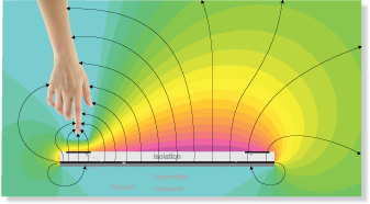
To increase the range of a radio system, it is possible to operate on the transmitter’s power, on the sensitivity of the receiver, or on both aspects. In the case of applications for IoT, the power produced cannot exceed 10-25 mW, so to comply with the rules that regulate the usage of ISM frequencies, and above all to limit consumption. To use again the example of the smoke detector, it is also true that the transmitter remains operative for a few seconds per day, after which it enters sleep mode and absorbs no more than a few nanoamperes, but we have to consider that in many cases the battery has to guarantee autonomy for 10-20 years. For this reason it is not possible to go beyond the said power values. On this subject, it also has to be noticed that it is not possible to continuously transmit on the ISM frequencies, but there is a limited “active time”; this is also one of the reasons why SigFox chose a maximum of 140 messages per day for each item. Going back to talk about the radio system, there is nothing left to do but to operate on the receiver’s sensitivity, and it is possible to do so by following different paths: SigFox chose the Ultra Narrow Band technology, Semtech chose Spread Spectrum. Both technologies aim to reduce the noise (locally produced and/or picked up from the immediate surroundings), so to increase the sensitivity. With these technologies and specific software algorithms, it was possible to reach sensitivities ranging between -126 dBm e -138 dBm, and performances also connected to the very low data transmission speed, that goes between about 100 e 300 bit per second. For most applications this low speed does not influence the performances of the network. In this article we will specifically deal with the technology and with the SigFox network, for two main reasons: the availability of a quite wide coverage at European level, with the first gateways that are going to be installed in Italy as well; and the availability of low-cost chips (such as the one by Atmel) with which to create the first interesting applications.


fig4


One Network A billion dream: this is the slogan by SigFox, the young French company that was the first to believe in a network specifically destined to items. It is a simple, cheap, scalable and easily implemented network. In the Figure shown we can see the configuration of this network with a series of radio gateways, capable of interacting with the items (a million and more for each gateway) that are found in the radio coverage area. The data received is sent via GSM or fixed telephone network to a central storage and processing system, and then “distributed” to the Clients by means of Internet APIs, capable of automatizing the devices management and of implementing the data integration. The infrastructure is so simple and inexpensive that the coverage of the whole French territory has been completed in a little more than a year. By using local partners, SigFox has completed the coverage in Netherlands, Spain, United Kingdom and part of Russia as well, and is making agreements with various other companies, capable of creating facilities in the whole of Europe and also in some zones of the United States of America.

Ultimately, therefore, a dedicated network being destined to IoT must present the following features:

  • Very low terminal energy consumption
  • Very long range radio connection, so to reduce the number of gateways
  • It must be cheap and easily integrated and scalable
  • It must be safe and reliable to avoid vulnerabilities.


All of these requirements are fully guaranteed by the devices and by the SigFox Infrastructure. As for the coverage of France, for example, less than one thousand gateways have been needed. The possibility to have a dedicated facility available, in order to give connectivity to whatever physical object, allows a multitude of opportunities, from the optimization of existing processes up to the creation of completely new businesses. The use of connected items is not surely new, but the sector’s growth is rapidly accelerating: it is calculated that the IoT will generate earnings for 1200 billions by 2020, in comparison with the 200 billions of today. The connected items are often simple, isolated and battery-operated, with sensors that detect certain events or pieces of information and send them to a centralized information system, ten or a hundred times per day.


fig3


The information may concern anything, from the energy consumption to temperature, humidity, position, presence detection, health data and so much more. The challenge for the traditional network connectivity suppliers lies in their capability of providing adequate solutions for these products; solutions that often cannot be provided by the existing technologies, be it as regards the energy consumption or the costs. Nowadays, it is clear that the applications connected to the Internet of Things have requirements that are very different from those of cellular phones and smartphones; in this last case we are moving along a path of a greater bandwidth and a greater processing capability, at the expense of the battery duration and of costs that are in any case high, and unacceptable for facilities with billions of connected items.

The other possibility, that of satellite connectivity, has the same problems of high costs and energy consumption, both being inconsistent with the development of widespread low-cost networks. Even the short-range connectivity solutions (Wi-Fi, ZigBee, ecc.) have a high energy consumption and are very complex to manage. Wi-Fi connectivity, as an example, requires the configuration of each item, while facilities like ZigBee require a high number of concentrators, with consequent increased complexity as for installation and maintenance, and even higher energy consumption. Finally, therefore, we return to the features of the SigFox network and, more in general, of the “low power long range” systems, otherwise known as LPWA (Low Power Wide Area), that turn out to be the most suitable for a rapid development of IoT facilities. Technically speaking, even a GSM/GPRS/LTE cellular system could be defined as long range, but it surely isn’t low-power. Not considering the fact that, on the contrary of GSM and satellite systems, LPWA devices operate on free radio frequencies that do not require public concessions.

The rapid deployment of solutions that are destined to the Internet of Things therefore requires dedicated facilities with long range but reduced consumption of about a few milliwatts (as for transmission), so to assure many years of operation without any kind of maintenance.

It has been calculated that a SigFox terminal with a last generation chip, powered by two 2.700 mA AA batteries, is capable of operating for about 20 years, sending 140 messages per day.

From the technical point of view, the network by SigFox considers a maximum of 140 messages sent per connected item, each day. Each message is made by a 12 bytes payload; in the case of longer data it is divided in more messages, so to respect the expected 12 bytes. Each device is identified by a 32-bit ID and by a PAC that can be used only once to register the SigFox ID.

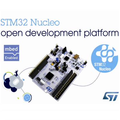
The new Atmel devices, and the ATA8520 chip in particular, integrate a low consumption TX for both transmission (a mere 32,7mA) and OFF mode (a mere 5 nA); the chip may operate with a voltage between 1,9 and 3,2 V and it is capable of supplying +14,5 dBm of RF power. Moreover the device integrates the SigFox stack, the ID, the PAC and it is predisposed for a cryptographic AES system, capable of guaranteeing the maximum security from this point of view. Communication is carried out by means of a SPI port and the chip requires about 10 external components to operate.


fig6


In the classic configuration, this device is controlled by a micro 8-bit AVR (ATmega328P).


fig5


These are the components that we will use in the next long-range IoT projects that we have in the planning stage.

Stay Tuned!


ArduDisplay, when the display becomes interactive!

$
0
0

featured_ardu


We are going to build an internet-connected, Arduino-based display, on which we could write directly from a smartphone, by sending the messages over WiFi.


In the late 90s of last century LED displays have begun to replace or complement the classic Signs on cinemas and business activities in general. Those displays could be programmed to allow owners to change messages every desired time, adding a sliding effect to the text (text-scrolling), in order to attract potential customers on the street, reporting their opening hours, promotions, news and any other useful information.

Today, in the IoT era (Internet of Things), we can integrate new technologies to LED display, increasing the interaction between it and users thus creating a kind of entertainment form that increases the permanence of the person in front of the display itself and, consequently, in the area where it is placed.


Figura1

Time Square (New York)  after the LED display era.


The project we will make allows people connecting to a WiFi network with their mobile devices, type a message through a web page and see it displayed on an LED display that we can place at our booth, at a fair or at a party, concert or club.

Our application will have a control panel (also accessible from the network) that will allow us to:

  • approve the messages received before sending them to the display,
  • set the displaying time of each message, the text scroll speed and a default message to display in the absence of messages received;

You can also decide not to filter messages: in this way all messages will automatically be placed in the queue to be displayed. Received messages will be deleted once displayed, but we can also choose to view them cyclically.


Components

To make ArduDisplay we will need:

  • Arduino Yun;
  • one to four LED display Sure 3208 (depending on how long we want our display);
  • a connection shield between Arduino and displays or male-male jumpers;
  • a microSD (bigger than 512 MB).


We have chosen to implement this project using Arduino Yun because this integrates: a microSD slot, a WiFi card and a Linux distribution called OpenWrt-Yun (from the most popular OpenWrt  ) that will allow us, with its 400 MHz processor and 64 MB dedicated RAM, to transform our Arduino into a web server equipped with PHP5 and MySQL database.

The Arduino source code will fetch messages through PHP (via the Bridge library) and display them on the screen, creating the text-scrolling effect, while the web server will allow users to send messages and allows us to manage them (approve or discard).

Messages and settings (for example, the text persistence) will be saved to a MySQL database.

PHP files and web pages will be stored on the microSD card, while the WiFi network that will connect users will be set up directly from Arduino.


Figura2

ArduDisplay functional scheme


The Sure Electronics LED display, and in particular the model 3208 we selected, has four 8×8 arrays each formed by 64 red, 3 mm adjustable intensity LEDs and is based on the Holtek HT1632C controller.

We can connect up to four displays in series thanks to IDC 16-pin cable; there are also two terminals with 5 V output voltage, if the current supplied by Arduino is not enough to feed all displays.

Our project will use, for simplicity’s sake, two of these displays.

Every display needs 0.36 Ah with all LEDs on at full intensity. Since we will use the default intensity (approximately half of the maximum available) and will not keep all LEDs on to display text, we will power the whole set through the Arduino pins 5V and GND (Arduino is powered through its Micro-USB connector).

As we said earlier, the microSD will store PHP files and web pages that will be visited by users to post messages, by us to manage the queue and by Arduino to pick them up and display them.

The wiring between the first display in series and our Arduino Yun will be made through a shield that will allow IDC cable direct connection to it.


Arduino Yún Configuration

In this section we will discuss the platform setup \in order to obtain as final result an Arduino web server capable of running PHP pages, store data to a MySQL database and create a local WiFi network called “ArduDisplay” that will not require a password to access it.

Also, when we will connect to “ArduDisplay” network we’ll type “http: //scrivi.mi” in the browser, and we will be redirected to the display sending messages page.


As a first step we download from our GitHub repositories the ZIP file containing the Arduino sketch, the necessary libraries to manage the display and the files to be put on microSD.

Once downloaded and unzipped, we’ll find, in addition to Arduino sketch and HT1632 folder, a folder named “Arduino” which must be put on the microSD root. This folder contains the ArduDisplay database installation and all PHP files that will be analyzed later; when done, insert the microSD into Arduino.


Figura3

MicroSD folder and files structure.


Unless your Arduino Yun is new, we should completely reset the default OpenWrt distribution: so we will delete any installations or configurations that could interfere with our project.

To reset the OpenWrt-yun, press the WiFi reset button (located next to the USB-A) for at least 30 seconds: Arduino will restore the factory settings, as if it had just been purchased; This will remove, among other things, all the files installed and also the network settings.

Remember that if following this guide something goes wrong you can always use this method to reset Arduino.

After the reset (or after you turn your new Arduino Yun on), you’ll notice a WiFi network named “Arduino Yun-XXXXXXXXXXXX” (where X represents the alphanumeric characters that vary for each Arduino). Let’s connect and type “http: / /arduino.local “or” http://192.168.240.1 ” to access the control panel, type the password (the default is” Arduino “), click on” Configure “, choose an existing WiFi network to connect to as we will need internet access; Let’s type the password if required and then click on the “Configure & Restart”.

Our Arduino will restart, connecting to the WiFi network that we set; at this point we need to find the IP address assigned by the router (eg 192.168.0.6) as it will be used to launch commands via SSH in the next step.

The IP address can be found in the router configuration page (usually reachable on 192.168.0.1 or 192.168.1.1) among the “Connected devices.”

The next step will be done through the command line, so we will connect to Arduino SSH shell using PuTTY.

Launch it and then insert in the “Host Name” field the Arduino IP address, click on the “Open” button, access as “root” with same password we used to connect to Arduino control panel. To install PHP5, launch the following two commands:


opkg update

opkg install php5 php5-cgi


Edit uHTTPd config file (OpenWrt-Yún integrated web server) to include PHP:


nano /etc/config/uhttpd


uncomment the line:


list interpreter “.php=/usr/bin/php-cgi”


Add the following line to have the uHTTPd to recognize “.php” files:


option index_page “index.php”


Close and save file (CTRL+X, Y and return).

Finally, restart uHTTPd server to enable the new settings:


/etc/init.d/uhttpd restart


Then we can install MySQL with the command:


opkg install libpthread libncurses libreadline mysql-server


Open MySQL config file:


nano /etc/my.cnf


Assign to “datadir” and “tmpdir” variables the following values:

datadir         = /srv/mysql

tmpdir          = /tmp


Close and save, then execute the following commands:


mkdir -p /srv/mysql

mysql_install_db –force

/etc/init.d/mysqld start

/etc/init.d/mysqld enable

mysqladmin -u root password ‘admin’


In this way we have created a MySQL server, associating it the user “root” and the password “admin”; Now we will have to install the MySQL module for PHP; to do this we run this command:


opkg install php5-mod-mysql


Open PHP config file:


nano /etc/php.ini


Uncomment the line:


extension=mysql.so


Also verify that you have the following block of code with parameters compiled in this way:


[MySQL]

mysql.allow_local_infile = On

mysql.allow_persistent = On

mysql.cache_size = 2000

mysql.max_persistent = -1

mysql.max_links = -1

mysql.default_port = 3306

mysql.default_socket = /tmp/run/mysqld.sock

mysql.default_host = 127.0.0.1

mysql.default_user = root

mysql.default_password = admin

mysql.connect_timeout = 60

mysql.trace_mode = Off


Save and close (CTRL + X, Y and Enter).


After creating the MySQL server we must populate it with our database and our tables. So let’s move to the folder where is the database:


cd /www/sd/


Open MySQL shell:


mysql -u root -p


And insert the database password, then run the following SQL command to create the database:


source ardudisplay.sql;


To verify that everything went well run these two commands:


use ardudisplay;

show tables;


We should see the table “frasi” (sentences) and the table “impostazioni” (settings).

Then exit from the MySQL shell:


exit


Figura4

Ardudisplay DB tables


Open the configuration file that will be used by our PHP files to connect to the database:


nano Common/db_class.php


Let’s make sure that this contains the parameters:


$this -> mysql_server = “localhost”;

$this -> mysql_username = “root”;

$this -> mysql_pass = “admin”;

$this -> database_name = “ardudisplay”;


Save and close (CTRL + X, Y and Enter).


Now that we have transformed our Arduino into a web server with PHP and MySQL database, we must ensure that when you type Arduino address on the browser, you are not redirected to the control panel, but to the page where to send posts; to do this we move to the folder where the web server files are, with this command:


cd /www/


Rename the file that redirects to control panel with these two commands:


cp index.html OLDindex.html

rm index.html


Create the PHP files that make the correct redirects:


nano index.php


Write the code inside:


<?php

header(“Location: sd/index.php “);

?>


Save and close (CTRL + X, Y and Enter).


After you clear your browser cache, when you enter the Arduino IP address you’ll be redirected to the message posting page.
At this point, we have to ensure that Arduino creates its dedicated Wi-Fi network. By holding down the Wi-Fi reset button for 5 seconds (but less than 30, otherwise we will lose all the work done so far) the initial network “Arduino Yun-XXXXXXXXXXXX” will be setup. Let’s connect to this network and go to control panel (http://192.168.240.1/cgi-bin/luci/webpanel/homepage), then click on “advanced configuration panel (luci) “, move to main menu’s “Network” section and then to subsection “Hostnames”.
In this section we will add a rule that will translate the IP address to “http: //scrivi.mi”: click on the Add button, insert “scrivi.mi” in Hostname field and select “–custom -” in the IP address field, then write “192.168.240.1”;

Finally click on “Save & Apply”.
At this point we will have the following addresses:


  • http://scrivi.mi to send messages to the displays;
  • http://scrivi.mi/sd/admin to manage the received messages and other settings (this section will be analyzed later in the article);
  • http://scrivi.mi/cgi-bin/luci/webpanel/homepage to connect to Arduino control panel.


The last operation we have left to do is changing the Arduino WiFi network SSID: we connect to advanced control panel (luci) using the new address, scroll down the page to the section “Wireless” and we click on our network name.
Then we type “ArduDisplay” in ESSID and we click on “Save & Apply”, wait until Arduino restarts and then connect to the network “ArduDisplay”.


PHP files analysis

Let’s look at the functions of each PHP file that we put on the microSD card.
In the “www” folder, which will be the root of our site, we find the file index.php: this file will be loaded immediately after typing “http: //scrivi.mi” and contains the text box to send a message to device.
The message will be received by the file invia_frasi.php who will write it in the database with a 0 status (to be approved) if we had set “Approve messages” to “Yes” in the control panel, otherwise 1 (approved), that means that our message will be directly queued to display without approval.
We then find the file ritorna_frasi.php, who will feed a new phrase every time Arduino will ask it through the “Process” object\; if the “Cycle phrases” mode is turned off it will extract the first sentence from the queue (with condition 1), otherwise the default sentence will be returned (it can be changed at any time from the control panel).

Each time you extract a sentence to show, this will be immediately deleted from the database.
If “Cycle sentences” mode is on the sentence extracted will not be deleted: in this way all the received sentences will be displayed cyclically.
The file ritorna_impostazioni.php is called by Arduino together with ritorna_frasi.php: they are responsible to set the screen duration (in seconds) of a phrase and the scroll speed (also selectable from the control panel that we will see below) to Arduino.


Moving to the “admin” folder, we find the index.php file that contains a simple text box to log in to control panel (via the file login.php); the default password to access the control panel is “admin”, you can change once logged.
Admin.php page allows us to do many different tasks: if “Approve phrases” option is active we will see the messages to be approved in the left box, the queued messages in the central box while in the right box we can change some ArduDisplay settings:


  • Password admin: It is the password to access the control panel;
  • Durata frase display: is the permanence time (in seconds) of a sentence on the LED display;
  • Velocità scroll: It is the text-scrolling speed;
  • Approva frasi: if set to “Yes”, the sentences must be approved before going to the display queue;
  • Ciclo frasi: phrases, once sent to the display, are not deleted since Arduino will cyclically show them;
  • Frase default: it is shown by default when no messages are present in the queue


Clicking the “Logout” button will invoke the file logout.php that will allow us to exit the ArduDisplay control panel.
The folder “Common” however, contains the javascript library that allows calls to be made to PHP files (jQuery), the CSS style sheet, the buttons images to approve or delete a received message and the db_class.php file that we analyzed in the previous paragraph and contains the PHP class and data to connect to the MySQL database.


Arduino sketch

In the ZIP archive you downloaded you will find a file named “ArduDisplay_v1.ino” and a folder called “HT1632″.
The display we used requires a library to work, represented by the above-mentioned folder.
To use it you must copy the entire folder to Arduino libraries directory (usually located in “Documents \ Arduino \ libraries”).
Now we can connect Arduino to the computer with the USB cable and open the file with the extension “.ino” in Arduino IDE.
Check that the COM port and Arduino model indicated by the IDE are correct, if so then you can proceed to compile and upload the code.
Let’s look at the code in the file by referring to Listing 1.


#include <Process.h>
#include <HT1632.h> 
#include <font_8x4.h>
byte numero_display=2;
byte wr =3;
byte data = 5;
byte cs1 = 6;
byte cs2 = 9;
byte cs3 = 0;
byte cs4 = 0;
int larghezzaTesto;
unsigned char* fraseCorrente =(unsigned char*) “”;
unsigned char* fraseVecchia =(unsigned char*) “”;
int translazione=0;
byte tempoDisplay;
int tempoDelay;
String id_frase=”-1”;
int iterazioni;
int cont=0;
void setup() {
  pinMode(13, OUTPUT);
  digitalWrite(13, HIGH);
  Bridge.begin();
  digitalWrite(13, LOW);
  switch(numero_display){
    case 1:
      HT1632.begin(cs1,wr,data);
      break;
    case 2:
      HT1632.begin(cs1,cs2,wr,data);
      break;
    case 3:
      HT1632.begin(cs1,cs2,cs3,wr,data);
      break;
    case 4:
      HT1632.begin(cs1,cs2,cs3,cs4,wr,data);
      break;
    default:
      break;
  }
  for(int i=0;i<numero_display;i++){
    HT1632.renderTarget(i);
    HT1632.clear();
    HT1632.render();
  }
  delay(40000);
}

void loop() {
  if(cont==0){
    for(int i=0;i<numero_display;i++){
      HT1632.renderTarget(i);
      HT1632.clear();
      HT1632.render();
    }
    caricaImpostazioni();
    cambiaFrase();
  }
  controlliDisplay();
  cont=(cont+1)%iterazioni;
}

void controlliDisplay(){
  for(int i=0;i<numero_display;i++){
    HT1632.renderTarget(i);
    HT1632.clear();
    HT1632.drawText(fraseCorrente, OUT_SIZE * (numero_display-i)-translazione , 0, FONT_8X4, FONT_8X4_END, FONT_8X4_HEIGHT);
    HT1632.render();
  }
  translazione = (translazione+1)%(larghezzaTesto + OUT_SIZE * numero_display);
  delay(tempoDelay);
}

void caricaImpostazioni(){
  Process p;
  String temp;
  p.begin(“/usr/bin/php-cgi”);
  p.addParameter(“-q”);
  p.addParameter(“/mnt/sda1/arduino/www/ritorna_impostazioni.php”);
  p.run();
  while (p.available()>0) {
    char c = p.read();
      if(c!=’|’){
        temp += c;
      } else {
        tempoDisplay=temp.toInt();
        temp=””;
      }
  }
  tempoDelay=temp.toInt();
  iterazioni=tempoDisplay*1000/tempoDelay;
}
void cambiaFrase(){
    Process p;
    String temp=””;
    p.begin(“/usr/bin/php-cgi”);
    p.addParameter(“-q”);
    p.addParameter(“/mnt/sda1/arduino/www/ritorna_frasi.php”);
    p.addParameter(id_frase);
    p.run();
    while (p.available()>0) { 
      char c = p.read();
      if(c!=’|’){
        temp += c;
      } else {
        id_frase=temp;
        temp=””;
      }
    }
    fraseVecchia=fraseCorrente;
    unsigned char b[temp.length()+1];
    temp.getBytes(b,temp.length()+1);
    fraseCorrente = b;
    if(fraseCorrente!=fraseVecchia){
      translazione=0;
      larghezzaTesto = HT1632.getTextWidth(fraseCorrente, FONT_8X4_END, FONT_8X4_HEIGHT);
    }
}


First, the libraries are included: the first one handles the communication between the two processors on the card, while the other two are necessary to manage the display, the third in particular associates to each character its graphical representation.

Then there is the number of displays, the declaration of pins needed for their control, followed by the variables declaration:


  • larghezzaTesto is the pixel width of the phrase to show;
  • fraseCorrente and fraseVecchia respectively indicate the sentence just received and the previous one, this is used to decide whether to reset the text position at the changing of the phrase (if the phrase does not change, it is not moved back to the origin, thus giving a sense of continuity);
  • translazione is the current phrase pixels shift respect to the origin;
  • tempoDisplay is the phrase displaying time, in seconds;
  • tempoDelay indicates the time in milliseconds to wait between two loop executions, a shorter time implies a greater sliding speed;
  • id_frase It is the database id of the sentence shown, and is required to implement the functionality “ciclo frasi”;
  • iterazioni indicates the number of times that the loop cycle must be executed before changing a sentence, this depends on tempoDisplay and tempoDelay, in fact if for example a sentence must be shown for 10 seconds with a time between one cycle and the other of 100 milliseconds, you will find that this will last for 100 cycles;
  • cont tracks how many iterations have been executed.


In “setup” instead we turn on a led that will be switched off as soon as the bridge between the two processors onboard has been established, then initialize the screen in different ways depending on the number of connected displays and clean it/them, waiting 40 second to start the WiFi network and Arduino web server.
In the cycle loop we check if the “cont” variable is equal to 0, this event occurs only when the program starts or when a sentence has been displayed for the set cycles number. If the occurrence is true, we turn off the display for the necessary time to change sentence. Then the functions caricaImpostazioni and cambiaFrase are invoked.
We then move on to the actual display management: the phrase is rendered on each screen with a proper shift (specific for each display) and then the shift is increased step-by-step (putting it to zero when the sentence has “passed” all the screens) waiting a period of time that depends on sliding speed (delay).
The last instruction of the loop increments the variable “cont”, setting it to zero when all the iterations have been executed.

The functions caricaImpostazioni and cambiaFrase invoke, using a Process type object, a PHP file present on OpenWrt-yun to manage the output they receive (a serial stream of characters).
The function caricaImpostazioni receives a text like “tempoDisplay | tempoDelay” then will extract from the string received the two parameters and assign them, after a conversion, to the relevant variables; cambiaFrase instead receives a stream of type “id_frase | message”.
While it is possible to directly assign the sentence id to its variable, to make the message just received understandable by the display libraries it is necessary to convert the String to Byte with the getBytes function. Finally we check if the new sentence is the same as the previous one: if not we cancel the translation vector and we conclude by calculating the width in pixels of the new sentence.
If you wanted to implement a different number of displays, simply change the variable numero_display and assign the correct pin number to variables cs1, cs2, cs3 and cs4.


Display Connection


After you have configured and loaded the Arduino sketch, we move to the connection between the display and the board; we can connect in two ways: the fastest way is certainly to use the dedicated shield, otherwise we will connect the first display to Arduino using the idc cable together with jumpers.
Following the figure we will connect jumpers to pins in the following way:


PIN Arduino PIN Display
3 WR
5 DATA
6 CS1
9 CS2
10 CS3
11 CS4
5V +5v
GND GND


After connecting the first display to Arduino, we can connect all the others in series using new IDC cables.
Regardless of the connection mode chosen, do not forget to set the address of each display (1 to 4) by using the dip switches on the rear.


Figura5

Connection between Arduino and the first display through jumpers.


Project end

At this point, we can position our ArduDisplay, power it (for example via Micro-USB) and wait about a minute for the software initialization and the setting of WiFi network.
If all went well, Arduino, finding no sentence to show, will display the default phrase.
We can connect with any device to the “ArduDisplay” network, type in the browser “http: //scrivi.mi” and send a test message.
Now let’s move to “http: //scrivi.mi/sd/admin”, accessing with the default password “admin” and confirm the message just received: after just a few seconds we will see it on display.


Figura6
Testing ArduDisplay.


From Store

ARDUINOYUN

Touch Display for Raspberry Pi

$
0
0

fig_0

We add to Raspberry Pi a TFT touch screen to display the system console, movies and favorite photos or control a relay board at your fingertips, literally!

To avoid using an HDMI monitor the cost well above that of Raspberry Pi, in previous articles we have always gone the way of connecting remotely to the microcomputer, using tools such as Putty and WinSCP. This approach has always bound to use Raspberry Pi in a “server” mode. Therefore we have always presented applications with user interface built to be accessible by web browser. What to do when we want to have an interface in traditional style, accessible directly from the desktop? Simple, you connect a monitor, a keyboard, a mouse and then you can code a standard desktop application using the classical languages ​​and libraries for creating graphical user interfaces. Yeah, but this way we transform Raspberry Pi in a PC with all devices attached, making it a traditional “cumbersome” uncomfortable device.

The solution we introduce instead of the “classical”, allows you to create graphical user interfaces using a nice 2.8-inch TFT color monitor with a touch resistive interface. No monitor, no keyboard and no mouse. The display board has more or less the same Raspberry Pi size, is already assembled and is compatible with all Raspberry Pi versions: A, B and B +. In this post we have adopted the model B + that provides a greater number of I / O pins than previous versions. The monitor has a resolution of 320 x 240 pixels with 16 bits color depth. The mini display is connected to Raspberry Pi through its SPI bus and can be used to redirect the console, or as a monitor to display the Raspbian X desktop, photos, video and user applications graphical interfaces. So far, so good. The downside is that the drivers are not included in Raspbian kernel.
This cute display allows us to introduce, in more detail than we have done up to now, the build of an embedded GNU / Linux system. In the “professional” field, embedded GNU / Linux distribution are the leanest possible, including only device drivers and essential applications to the basic microcontroller operation. This is to minimize the distribution memory footprint and maximize the target system performance. This approach allows the use of a reduced performance chip, with final solution physical dimensions as low as possible and minimum power consumption in order to allow battery operated solutions.

The downside is that you must customize the distribution kernel with the device drivers that you want to use, such as WiFi dongle, USB devices, LCD and LED panels. One of the advantages using Raspberry Pi has always been the ease of use, not having to deal with these issues. Being an “educational” microcomputer, Raspbian already includes a huge amount of drivers that meet automatically (plug and play) the most needs. This time, however, the TFT LCD drivers are not included. Fortunately, Adafruit (display producer) has provided a Raspian kernel, already compiled, that includes the required driver.

This avoid us having to customize Raspbian. We are still planning to propose a series of posts about the topic, because the continuous presence of new devices on the market requires fronting this issue definitely. In the Adafruit solution, there are in fact two problems. What to do when we have to connect a second device whose specific drivers are not included on the Linux kernel? Although the manufacturer makes available a “compiled” kernel for its device, we will lose other drivers integrations. The only solution is that we must configure and compile the kernel by our own, adding all the drivers requested. Second problem. Using the precompiled kernel, customized with the addition of a specific driver, it binds us to the kernel version used for compilation. In this condition, we will not be able to adopt new distributions with most recent kernels, unless the device manufacturer itself does not release a new version.

In this regard we remind that has just been released the 3.16 Linux kernel version, which has considerable additional functionality when it relates to ARM chip management with CPU and its graphics processors. A sign that we will see an increasing spread of our “philosophy”.


fig_1


But back to our graphic display based on TFT LCD module ILI9340, which comes pre-assembled and equipped with GPIO connector, present on all Raspberry Pi models: A, B and B +. The board includes the display controller STMPE610 communicating with Raspberry Pi through the SPI bus and then engages the corresponding GPIO connector pin (SCK, MOSI, MISO, CE0, CE1) in addition to GPIO25 and GPIO24 pins. The four additional buttons present on board are connected to pins GPIO23, GPIO22, GPIO21, and GPIO18. All other pins are unused and may be used for other needs. In this case it is appropriate to solder a connector on housing present on the right side of the card and use a flat cable extension. Be careful to follow the right pin matching. The GPIO pin number 1 is signed on the back of the board with a square shape and a small white arrow silkscreened.


How to customize Raspbian

The process we describe to set up the TFT LCD requires starting from Raspbian. We used the image released on 9 September 2014kernel release 3.12 .


fig_2


Now it is better not to install the display on the connector, we will do it after you install the software. To perform the installation process it is necessary that Raspberry Pi is connected to the local network so you can see” Internet. You also need to access to Raspberry Pi to use a terminal window and a file manager. As always, but especially in this case, we prefer to remotely access via SSH using (in Windows) Putty and WinSCP. Of course, you can also connect to the console via serial cable.
We login to Raspberry Pi with the user “rootand start the installation process with the usual commands to update the distribution:

apt-get update

apt-get upgrade

We go to a temporary folder to download the installation files. We can also create a specific folder for this process. The files are available as .deb packages which must then be installed with dpkg. We can use, for example, the “home” folder. We go there with the command:

cd /home

Now we download all the necessary packages to upgrade the kernel for the display management.

wget http://adafruit-download.s3.amazonaws.com/libraspberrypi-bin-adafruit.deb

wget http://adafruit-download.s3.amazonaws.com/libraspberrypi-dev-adafruit.deb

wget http://adafruit-download.s3.amazonaws.com/libraspberrypi-doc-adafruit.deb

wget http://adafruit-download.s3.amazonaws.com/libraspberrypi0-adafruit.deb

wget http://adafruit-download.s3.amazonaws.com/raspberrypi-bootloader-adafruit-20140917-1.deb

After the download, from the same folder, install everything with the command:

sudo dpkg -i -B *.deb

This takes quite a long time, you can take a break and relax for a moment. If you are using an old Raspbian (prior than September 2013), you must disable the use of the accelerated framebuffer X, with the command that removes the configuration file of the accelerator and saves it to the folder / home (you never know):

mv /usr/share/X11/xorg.conf.d/99-fbturbo.conf /home

Now we turn off Raspberry Pi with the traditional command:

shutdown –h now

We remove the power plug; insert the display on the GPIO connector, making sure that there is no false contact with any other Raspberry Pi connector or component and then we power on. Do not worry, on the small screen, for the moment, nothing will appear. We reconnect to Raspberry Pi with Putty and WinSCP. To test display operation we can quickly load the driver from the command line and launch Raspberry Pi desktop. We type the following commands in the order, as visible in figure:


fig_3


modprobe spi-bcm2708

modprobe fbtft_device name=adafruitts rotate=90

export FRAMEBUFFER=/dev/fb1

startx

You should see the Raspberry Pi desktop on the small screen.


fig_4


You can also use the menu bar and applications in “touch” mode. If all goes well the most important step has been made. Now we make sure that everything will start automatically when you turn on Raspberry Pi. We close the graphical desktop (actually the X server) from the terminal window by simultaneously pressing <ControlX>. We open the following file from WinSCP:

/etc/modules

and append at the end of the file the two modules to be loaded at startup:

spi-bcm2708

fbtft_device

Save and close the file. We insert password to save. One moment, we’re not done, we have to add a configuration file to customize the display rotation and image refresh rate parameters. Open the file:

/etc/modprobe.d/adafruit.conf

and add the following configurations:

options fbtft_device name=adafruitrt28 rotate=90 frequency=32000000

The parameter “rotateallows you to rotate the display to 0, 90, 180 or 270 degrees so that it can adapt to all assembly situations.

0 corresponds to the vertical display, with the lower side towards the printed markings on the base;
90 corresponds to the horizontal display, with the bottom towards the buttons;
180 corresponds to the vertical display, with the top side towards the printed markings on the base;
270 corresponds to the horizontal display, with the top side towards the buttons
.

The parameter frequency” indicates the refresh rate of the display. The value 32000000″ means 32MHz and corresponds to a frame rate of about 20FPS. If the total load of your application allows it, you can try to lower the frequency to 16 MHz (16 million). Let’s make the changes effective with a command:

reboot

After reconnected, check the console messages with the command:

dmesg

we focus on recognition of the STMPE610 controller and on the ILI9340 display frequency setting as shown in figure.


fig_5


We can double check if everything is working by launching the X desktop with the command:

FRAMEBUFFER=/dev/fb1 startx

To stop the execution, press <ControlX>.
It’s all done? Not yet, now we have to set up and calibrate the touch screen so that it can work both with the graphical desktop and with applications that we’re going to develop. As a first step we set a rule in the folder udev linking the touchscreen device to the correct input device. It can happen that the touchscreen is recognized in the / dev / input as a different “event” depending on whether or not there are keyboard, mouse or other input devices. We create the file

95-stmpe.rules

In folder:

/etc/udev/rules.d/

and insert the following configurations:

SUBSYSTEM==”input”, ATTRS{name}==”stmpe-ts”, ENV{DEVNAME}==”*event*”, SYMLINK+=”input/touchscreen”


fig_6


Remove and re-install the touchscreen driver with the commands:

rmmod stmpe_ts

modprobe stmpe_ts

At this point in /dev/input we will find the device touchscreen” that points to the correct device “event <x>”. You can check this with the command:

ls -l /dev/input/touchscreen


fig_7


We will see the description of the device file with the connection (the arrow) to a device “event (x)”. Now we must calibrate” our touch screen. There are two ways to do this, one a bit more coarse” but automatic, the other more accurate but more complex and long run. For our needs, since we are lazy too, we will use the “Automatic” method by using a Python program created and kindly provided by Adafruit. Before, we must install a library useful to perform tests on the touch screen.

apt-get install evtest tslib libts-bin

We can already do a test by typing:

evtest /dev/input/touchscreen

If we touch the display at various positions we will see events recognized and touch-point coordinates.


fig_8


For the real “coarse” calibration, we download the Python program from Adafruit site and make the folder to contain the configuration file. Download the program with the command:

wget https://github.com/adafruit/PiTFT_Extras/raw/master/pitft_touch_cal.py

Let’s create the folder xorg.conf.d:

mkdir /etc/X11/xorg.conf.d/

and execute the calibration program from the same folder where we downloaded:

python pitft_touch_cal.py

Look at the program output, before updating the configuration file the program asks you to confirm, if you are satisfied with the results confirm with Y”.


fig_9


Displaying the Console on the screen

A nice setting that you can do is to redirect console messages to the display instead of the standard video output. Although the screen is small, if you choose the right font you can get an area of 20 lines per 40 characters. To accomplish this we must edit the kernel configuration file in the file system boot partition. Open the file:

/boot/cmdline.txt


fig_10


The purpose of the change done is to redirect the console from the frame buffer HDMI / TV standard /dev/fb0 to the frame buffer of the display TFT /dev/fb1. To do that go down to the directives, after the entry “rootwait” and add the statements:

fbco n=map: 10 fbco n=fo nt: VGA8x8


fig_11


Save the file and reboot. Note that, during the initial load, you’ll miss the multicolored splash screen and the initial part of the console messages. This is absolutely normal, because, in order to work, the driver must be loaded by the kernel and activated, which occurs after the boot start process. Then you will see the console messages, as shown in figure.


fig_12


To change the VGA8x8 font into something more readable, i.e a 12×6, run the console reconfiguration command:

dpkg-reconfigure console-setup

follow the steps on figures to select the font “Terminus 6×12”.


fig_13


fig_14


fig_15


fig_16


Displaying videos

You can view on our display many video files with different extensions, if the resolution is 320 x 240 pixels. To see a video we use the package “mplayer”, if it is not already present in our system we install it with the command:

apt-get install mplayer


fig_17


To see the video we give the command on figures:

mplayer -vo fbdev2:/dev/fb1 -x 240 -y 320 -framedrop <file-video.ext>

as example “ProvaVideo.mp4”


fig_18


fig_19


fig_20


If the video is not in 320 x 240 resolution we can resize it using the tool HandBrake, Open Source and available for all operating systems. Download it from https://handbrake.fr/. Once installed we use it to resize the test video. Open the file, preferably with the .avi extension.


fig_21


The window shows many info from the uploaded file. In the “Destination” field insert the path and file name that we want to get.


fig_22


In the panel below: In “Output Settings” in the “Container” field, just select MP4″; in Width” we set 320. In Anamorphic select Custom” and Modulus” set 2.


fig_23


Click on the “Start” button to start conversion.


fig_24


At the end, if we run the conversion in Windows OS, just move the file to Raspberry Pi and run the command described at the beginning of the paragraph to play the file.


fig_25


Displaying pictures

Another nice application is for displaying pictures. To do this we use the package fbi”: frame buffer image viewer. We install it with the usual command:

apt-get install fbi

Also in this case the images must have a max size of 320 x 240 pixels. To view an image we use the command:

fbi -T 2 -d /dev/fb1 -noverbose -a <picture-name >.jpg


fig_26


Setting the backlight level

The backlight of the TFT display is done through four LEDs which absorb a total of about 75 mA. If we power the board through battery or if you still want to turn the backlight off, the STMPE610 touch controller has two I / O pins and one of these is connected to the transistor that controls the backlight. This pin is accessible from the command line as a Raspberry Pi GPIO terminal, recognizable as GPIO 252. To access the GPIO you must export its device file with the command:

echo 252 > /sys/class/gpio/export

with:

ls -l /sys/class/gpio

You can check the actual existence of the GPIO. We declare the pin I / O as output with the command:

echo ‘out’ > /sys/class/gpio/gpio252/direction

Now we turn the backlight on by setting the pin value to “1″ with the command:

echo ‘1’ > /sys/class/gpio/gpio252/value

To turn off the backlight, use the opposite command:

echo ‘0’ > /sys/class/gpio/gpio252/value


Writing an app

What can we do with such a nice display, other than managing Raspberry Pi console or desktop GUI? We can write our applications, to communicate with the GPIO and any other external sensors. The possibilities are so many.

But if we want to develop a very simple starting application, we have to reduce this possibilities, always doing something really interesting. We will use Python to create a graphical interface that can control the IN/OUT shield outputs. To interact with the TFT graphic display we will exploit the functionality available in pygame, the library to create video games and graphics applications in general. In recent Raspbian distributions, pygame library is already included and installed. If not, we install it through the Manared Python Package named “pip” (pips Installs Python), with the command:

pip install pygame

If we had not pip” installed, install it with the command:

Apt-get install pip

Done? Check the installation by using python from the command line. We check that everything is working by typing one after another the following instructions:

import pygame

import os

os.putenv(‘SDL_FBDEV’, ‘/dev/fb1′)

pygame.init()

lcd = pygame.display.set_mode((320, 240))

lcd.fill((255,0,0))

pygame.display.update()

pygame.mouse.set_visible(False)

lcd.fill((0,0,0))

pygame.display.update()

Among the important instructions, see the one that sets the fb1 device as framebuffer, the pygame library init. After, we set the display definition we called “LCDwith resolution of 320 x 240 pixels. The other instructions change the screen background color, using the usual RGB coding. We conclude with one last little project that allows us to command four relays with touch controls on the TFT display. We use the RELAY4CH2846 board (available from Futura Elettronica) which hosts four relays, is powered at 5 volts and is drivable with direct or optocoupled digital inputs: those accept voltages from 1.5 to 5V and therefore are compatible with the Raspberry Pi GPIO output. We choose the direct coupling by placing a jumper on the COM and GND terminals. Now connect the card to Raspberry Pi as in the diagram in figure.


fig_27


We connect the power supply and four GPIO pins driving the relays. We chose GPIO12, 16, 20 and 21 pins, very convenient to connect on the B+ version GPIO.

To power up the board weld a strip of male connectors on the GPIO “replica” present on TFT module using pins 2 (positive) and 6 (mass) with female-female cables. In Listing 1 we see the program to drive the relays. It is always a Python program. For the graphical interface we used the pygame library, which we have just described. The list is full of comments. The code logic is the initial construction of the graphic interface. The dictionary contains the central position coordinates where we want each pin description. The “for” loop outside the main loop prepares the display area with the writings for the four pins. The word “off” is added to each pin’s “name”. The whole is colored in red and positioned so that the center corresponds to the coordinates contained in the dictionary. Finally, the display is refreshed and the text become visible. When the code is running, if you tap on a pin name the corresponding relay changes state while the text color indicates its current status: red if off and green if on, as shown in the photo of figure.


fig_28


In future posts we will see how to use the display with other shields and with extended functionality, like the ability to operate a device directly from the display or from a webpage.

For now, just enjoy experimenting.

Listing 1


#!/usr/bin/python
# TFT_Rele.py.py
# Import librerie
import pygame
from pygame.locals import *
import os
from time import sleep
import RPi.GPIO as GPIO # GPIO management library 
# set pin as output
GPIO.setmode(GPIO.BCM) # uses GPIO enumeration
GPIO.setup(12, GPIO.OUT) # Set pin as OUTPUT
GPIO.setup(16, GPIO.OUT)
GPIO.setup(20, GPIO.OUT)
GPIO.setup(21, GPIO.OUT)
GPIO.output(12, False) # set pins to off
GPIO.output(16, False)
GPIO.output(20, False)
GPIO.output(21, False)
# color definitions (R, G, B)
WHITE = (255,255,255)
RED = (255,0,0) 
GREEN = (0,255,0)
BLACK = (0,0,0)
# system variables to define the device, the
# display and touchscreen
os.putenv('SDL_FBDEV', '/dev/fb1')
os.putenv('SDL_MOUSEDRV', 'TSLIB')
os.putenv('SDL_MOUSEDEV', '/dev/input/touchscreen')
# relays initial status
pin12='off'
pin16='off'
pin20='off'
pin21='off'
#init pygame
pygame.init()
# hydes the mouse pointer from display
pygame.mouse.set_visible(False)
lcd = pygame.display.set_mode((320, 240))
# black screen
lcd.fill(BLACK)
pygame.display.update()
# set font 
font_big = pygame.font.Font(None, 50)
# dictionary Key=pin value=coordinate writing center 
touch_buttons = {'12':(80,60), '16':(240,60), '20':(80,180), '21':(240,180)}
# set the initial screen status 
for k,v in touch_buttons.items():
b = k + ' off' # Scritta con pin + off
text_surface = font_big.render('%s'%b, True, RED) # red text
rect = text_surface.get_rect(center=v) # centers the text
lcd.blit(text_surface, rect) # put text on the display
pygame.display.update()
# main program loop
while True:
# waiting display event 
for event in pygame.event.get():
if(event.type is MOUSEBUTTONDOWN): # Display tapped 
pos = pygame.mouse.get_pos()
print pos
elif(event.type is MOUSEBUTTONUP): # finger released from display
pos = pygame.mouse.get_pos() # recall finger position 
print pos
# reckon which quarter of the display is the finger
x,y = pos
if y < 120:
if x < 160: # up and left
print 12
v = touch_buttons.get('12') # finds text center
if pin12 == 'off': # if off
pin12 = 'on' # sets to on
GPIO.output(12, True) # pin level high
b = '12 on' # on text
color = GREEN # Color green 
else:
pin12 = 'off'
GPIO.output(12, False)
b = '12 off'
color = RED
else: # up and right
print 16
v = touch_buttons.get('16') 
if pin16 == 'off':
pin16 = 'on'
GPIO.output(16, True)
b = '16 on'
color = GREEN
else:
pin16 = 'off'
GPIO.output(16, False)
b = '16 off'
color = RED
else:
if x < 160: # down and left
print 20
v = touch_buttons.get('20') 
if pin20 == 'off':
pin20 = 'on'
GPIO.output(20, True)
b = '20 on'
color = GREEN
else:
pin20 = 'off'
GPIO.output(20, False)
b = '20 off'
color = RED
else: # down and right 
print 21
v = touch_buttons.get('21') 
if pin21 == 'off':
pin21 = 'on'
GPIO.output(21, True)
b = '21 on'
color = GREEN
else:
pin21 = 'off'
GPIO.output(21, False)
b = '21 off'
color = RED
# draw the right display portion 
# and updates it
text_surface = font_big.render('%s'%b, True, color)
rect = text_surface.get_rect(center=v)
lcd.fill(BLACK, rect) # delete the previous text
lcd.blit(text_surface, rect) # Place the new text
pygame.display.update() # redraw the display
sleep(0.3) # waits
GPIO.cleanup()
# TFT_Rele.py.py

# Import librerie

import pygame

from pygame.locals import *

import os

from time import sleep

import RPi.GPIO as GPIO # GPIO management library

# set pin as output

GPIO.setmode(GPIO.BCM) # uses GPIO enumeration

GPIO.setup(12, GPIO.OUT) # Set pin as OUTPUT

GPIO.setup(16, GPIO.OUT)

GPIO.setup(20, GPIO.OUT)

GPIO.setup(21, GPIO.OUT)

GPIO.output(12, False) # set pins to off

GPIO.output(16, False)

GPIO.output(20, False)

GPIO.output(21, False)

# color definitions (R, G, B)

WHITE = (255,255,255)

RED = (255,0,0)

GREEN = (0,255,0)

BLACK = (0,0,0)

# system variables to define the device, the

# display and touchscreen

os.putenv('SDL_FBDEV', '/dev/fb1')

os.putenv('SDL_MOUSEDRV', 'TSLIB')

os.putenv('SDL_MOUSEDEV', '/dev/input/touchscreen')

# relays initial status

pin12='off'

pin16='off'

pin20='off'

pin21='off'

#init pygame

pygame.init()

# hydes the mouse pointer from display

pygame.mouse.set_visible(False)

lcd = pygame.display.set_mode((320, 240))

# black screen

lcd.fill(BLACK)

pygame.display.update()

# set font

font_big = pygame.font.Font(None, 50)

# dictionary Key=pin value=coordinate writing center

touch_buttons = {'12':(80,60), '16':(240,60), '20':(80,180), '21':(240,180)}

# set the initial screen status

for k,v in touch_buttons.items():

b = k + ' off' # Scritta con pin + off

text_surface = font_big.render('%s'%b, True, RED) # red text

rect = text_surface.get_rect(center=v) # centers the text

lcd.blit(text_surface, rect) # put text on the display

pygame.display.update()

# main program loop

while True:

# waiting display event

for event in pygame.event.get():

if(event.type is MOUSEBUTTONDOWN): # Display tapped

pos = pygame.mouse.get_pos()

print pos

elif(event.type is MOUSEBUTTONUP): # finger released from display

pos = pygame.mouse.get_pos() # recall finger position

print pos

# reckon which quarter of the display is the finger

x,y = pos

if y < 120:

if x < 160: # up and left

print 12

v = touch_buttons.get('12') # finds text center

if pin12 == 'off': # if off

pin12 = 'on' # sets to on

GPIO.output(12, True) # pin level high

b = '12 on' # on text

color = GREEN # Color green

else:

pin12 = 'off'

GPIO.output(12, False)

b = '12 off'

color = RED

else: # up and right

print 16

v = touch_buttons.get('16')

if pin16 == 'off':

pin16 = 'on'

GPIO.output(16, True)

b = '16 on'

color = GREEN

else:

pin16 = 'off'

GPIO.output(16, False)

b = '16 off'

color = RED

else:

if x < 160: # down and left

print 20

v = touch_buttons.get('20')

if pin20 == 'off':

pin20 = 'on'

GPIO.output(20, True)

b = '20 on'

color = GREEN

else:

pin20 = 'off'

GPIO.output(20, False)

b = '20 off'

color = RED

else: # down and right

print 21

v = touch_buttons.get('21')

if pin21 == 'off':

pin21 = 'on'

GPIO.output(21, True)

b = '21 on'

color = GREEN

else:

pin21 = 'off'

GPIO.output(21, False)

b = '21 off'

color = RED

# draw the right display portion

# and updates it

text_surface = font_big.render('%s'%b, True, color)

rect = text_surface.get_rect(center=v)

lcd.fill(BLACK, rect) # delete the previous text

lcd.blit(text_surface, rect) # Place the new text

pygame.display.update() # redraw the display

sleep(0.3) # waits

GPIO.cleanup()


From the store

Raspberry B+

TFT 2.8 Inch Touch hat

Starter Kit Raspberry PI

Raspberry Pi 2 or, better, “Four”!

$
0
0

featured


Tens of thousands of units sold in a few hours, a respectable performance, costs unchanged, here is where Raspberry Pi has decided to be in our future.


Here it is. On the desk, switched on, working, calmly, and cold it is processing our applications written for the previous Raspberry Pi model… with eye-rolling performances. We are talking about Raspberry Pi 2. Same aspect of version B + but a heart with four CPUs and one GB of memory. Those who live in the computing world were waiting for it so many years, despite the claims by the foundation, which indicated a certain “stability” of production on well-established models. Obviously, this position appeared as a sign of continuity for a product intended for the “education” market by vocation. On the contrary, some news heard here and there left us quite perplexed, and invited us to keep antennas high. For those of my age, the memory of the statements from Mr. Moore, cofounder of Intel, which in 1965 had found that from 1959 to then, every 18 months the number of transistors in a microcontroller doubled and consequently the computational performances while the processing costs were reduced in inverse proportion. As can be seen in figure this trend has been always respected until now, with little variance, so Moore’s observation has been promoted to the rank of law, known as the “first law of Moore.”


Fig1


So, logically, also Raspberry Pi would have to follow it. A conviction also strengthened by the continuous appearance of Raspberry Pi clones with more powerful CPUs and with operating systems and applications poorly compatible with each other. And some suspects have been generated by Raspbian distributions by the Raspberry Pi foundation, released more frequently, with changes to the “root” partition found … suspicious, as the appearance of the .dtb hardware configuration file: we’ll talk more about it later. Finally, the historical moment we are living is classified as a deep crisis. But as always happens, crisis periods are those when revolutionary ideas and solutions mature, marking the way for the next growth and prosperity period. Clearly, times of crisis are also accompanied by disparities, from technologies that are losing their importance and economic viability to others who appear on the scene so disruptive. Some are ephemeral, others are destined to last for a long time and support the rebirth. Probably one of those to last is the Raspberry Pi foundation that, at least in our opinion, is managing in the best way the innovative thrust, while maintaining full compatibility with previous versions, behavior that in the past was the main reason for their survival till today.

The way we test it was to take out the SD Card with our applications in development, to be honest too slow with the Raspberry Pi “1 gen” and insert it in the new … monster. It all run without hesitation with performances definitely not comparable.

First things first. Let’s see what has changed in the “body and under the hood” of the new Raspberry Pi 2. First, what didn’t change? The dimensions, mounting holes, the connectors and SD Card slot positions. So you can reuse boxes and housings. Clearly what has changed is the layout of the components on the PCB, given the increased size and number of the main chips. Oh, and the price has not changed since the previous version. Also for the “law” of Moore.

Let’ see, instead, what are the technical specifications: where the changes are!


Technical Features

To recognize if what you have in hand is a Raspberry Pi 2 or an “old” Raspberry Pi B + you can analyze the following elements, which are visible in Fig. 2 and 3 along with indications of main components positioning. First, “Raspberry Pi 2 – Model B” is written on top of the printed circuit. Then the processor with the Broadcom logo, always on top of the printed circuit and the memory chip that is located in the lower part of the printed circuit board.


Fig3


  • Broadcom BCM2836 CPU ARM Cortex-A7 900MHz quad-core
  • VideoCore IV GPU
  • RAM: 1GB LPDDR2 SDRAM

Other features are the same as Raspberry Pi B+

  • 4 USB standard ports on a dedicated bus
  • Ethernet 10/100 Mb
  • video HDMI and A/V output


Fig4


  • GPIO 40 pin with 26 pin for I/O, bus UART, I2C, SPI
  • CSI (Camera serial Interface) connector
  • DSI (Display Serial Interface) connector
  • a micro USB for the power supply, at least by 2A since the board-only power consumption is close to 700 mA/5V; if you use a 1A power supply, a single USB device connected will overtake the capacity, causing instability.


Fig2


On figutre you can see the Raspberry Pi 2 GPIO pinout, unchanged respect to Raspberry Pi B+


Fig5


On next figure it is visibile the 4 core CPU evidence, shown through command:

cat /proc/cpuinfo


Fig6


while in this figure you can check the used and total memory


Fig7


Big focus on compatibility

This feature list could suggest a simple upgrade of the world famous microcomputer, to adapt it to the possibilities offered by new technologies. Instead, in our opinion, there’s much more. In particular, the foundation choice to safeguard the investments dedicated to developing software, operating systems and user applications, adapted and made particularly efficient to run on Raspberry Pi “previous series”, with Broadcom BCM2835 processor. We are talking of thousands of hours invested, with associated costs spent “porting” the GNU / Linux Debian on ARMv6 hardware, including hardware support for floating point operations and to make the distribution itself more stable and performing. Just as much work and financial commitment has been spent optimizing for Raspberry Pi a large amount of libraries and open source applications such as WebKit, LibreOffice, Scratch, Pixman, XBMC / Kodi, libav and PyPy. Finally, the effort made in developing and optimizing tools that could make life easier for novice users (and not) as NOOBS tool that lets you manage different GNU / Linux on the same microcomputer, switching easily from one to another, or raspi-config configurator or rpi-update, the root partition update package. In addition, many independent developers have built applications, tutorials, books and documents based on Raspberry Pi. Switching to a new hardware often means invalidating all these investments, software and expertise to “start over” from scratch on new platforms with characteristics often not compatible with the previous ones.

Even very large organizations in hardware and software business, in the past as today, haven’t been immune to this issue. Developing the new Raspberry Pi 2, this has been safeguarded. Broadcom made available the new BCM2836 SoC where the “old” CPU ARMv6 was “cut out” and replaced with the new Cortex A7 quad-core.

The 1 Gb memory bank has been placed in the back of the PCB, advantaging the cooling capacity of the main processor. The VideoCore IV processor is the same as the BCM2835. The Raspbian kernel porting has been necessary to adhere to the hardware specifications of the new Soc. This step has proved successful because of the GNU / Linux operating system architecture, designed on purpose for this type of operation. GNU / Linux is an operating system belonging to the family of “monolithic kernel systems “, with a clear separation between “kernel space” and “user space”. The aim is to simplify the life of the system user, interfacing and “normalizing” the communication between applications and physical hardware devices on the computer. In extreme synthesis, the kernel (core) of the operating system, among other things, is responsible for interfacing the hardware (CPU, memory, bus, and physical devices) and provide a first level of standardized driver. The next layer, deals with further simplify the modalities of communication with peripherals, normalizing the whole set and making it “accessible” to the end user through the “virtual” file system that is the only “window” available to communicate with the physical system. In fact, the virtual file system is the line between what we have called “kernel space” and the “user space” where we write and / or we develop our applications. The architecture of GNU / Linux has already been described several times on magazines and in the book “Raspberry Pi – My first Linux embedded” (which, by the way, remains valid also for Raspberry Pi 2). The components “outside of the kernel” have not been optimized yet for the new CPU, in order to maintain compatibility with the previous board. This will happen time by time, according to the foundation, carefully selecting which library to upgrade to get the best combination of functionality, stability and performance of both worlds. Already now, among other innovations, it worth noting the availability of new operating system distributions aimed at the new version, including Snappy Ubuntu Core for Developers, already available for download in alpha version and … listen, listen: Windows 10 for Raspberry Pi, that shall be distributed free to developers.


Fig8


Fig9


Both these distributions are oriented to development of IoT (Internet of Thing) applications, a universe in turmoil that envisions a future a world increasingly interconnected but the contours of which are still being defined, at least that’s the my personal opinion. What is important is the presence of these two distributions on the official list, attracting attention and the consequent support, especially a financial one, that the two competitors on the market Microsoft for Windows 10 and Canonical for Ubuntu Snappy are reserving to Raspberry Pi foundation, although not exclusively. The major point is the acknowledgment by the big software houses that the information technology is moving towards “non-traditional” applications such as automotive, industrial automation, and home environment, mobile, that are growing in number and pervasiveness.


Turn Raspberry Pi 2 ON

To give life to our new Raspberry Pi we have several options, the first is to download the new Raspbian or NOOBS tool from the official Raspberry Pi site. Put the image file on a micro SD Card (attention, the SD Card in standard format is no longer needed, although now almost all the SD Card in the market are made up of a micro SD card and an adapter), insert it into the slot on the microcomputer and connect the power supply via the micro USB connector. For those approaching for the first time to Raspberry Pi, this is definitely the preferred method. Also, you can apply almost all the instructions in the book mentioned above.

Anyone who is a user of earlier Raspberry Pi versions can verify that the distributions released before 01.31.2015 cannot work, of course, on the new microcontroller. In this situation, one possibility is to do a backup of your files, install a “fresh” distribution and restore our files. In this way we will have to reinstall all the packages but also reconfigure them according to our needs. A considerable amount of work that conceals pitfalls and at least force us to re-test all the features. We preferred the third way, or perhaps the best way to be chosen if you use Debian GNU / Linux. Again, we wanted to have the new jewel compatibility tested in the rudest way possible. Some of the SD Card we use daily to work date back to the first Raspbian distributions appeared in 2012. Of course, they have always been updated with the commands we recommend in each article and in some cases they have been cloned by transferring the image from the original to a newest SD Card. Besides, we recommend a regular “maintenance” of the SD Card as their use on microcomputers shorten their life. The SD Cards have a maximum number of “writing on memory” operations allowed, a very big number indeed, which guarantees eternal life if being used in cameras, smartphones, tablets and similar. In microcomputer applications with high intensity of writing, in particular with the use of the database, the records are concentrated mainly on the same “cell area” of ​​the SD Card, and sooner or later the maximum number of operations is achieved resulting in crashes and data loss. So if you develop applications as a “professional” with Raspberry Pi, which becomes absolutely possible with the new version, it is essential to take into account and carefully plan backups and data protection strategy. Having said so, we have taken two of our historical distributions and, using a previous version of Raspberry Pi, we connected to the same network and we performed a series of commands that allow you to fully update our distribution to run on the new Raspberry Pi, including the kernel. If you’re in our situation, we recommend this method. As a first step we recommend that you create a backup image of the SD Card, using WinDiskImager. Then, update the distribution in the usual way, the user logged in as “root” with the command:


apt-get update

apt-get upgrade

apt-get dist-upgrade


If the distribution is not updated for some time, the process will be quite long. From a certain version on, Raspbian adopts a new release of the graphical LXDE (Lightweight X11 Desktop Environment), which settle the taskbar at the top of the screen, a blank desktop to be populated with our preferred applications and the “Start” menu in top left. We can update the distribution to the new GUI with the command:


apt-get install raspberrypi-ui-mods


After, keep the distribution clean with the commad:


apt-get autoremove


which removes unused packages and:


apt-get purge


which removes unused config files.

Then update the root partition with command:


rpi-update


if you get an error such as “command not found” you can install the upgrade tool with the command:


apt-get install rpi-update


Everything done? You can turn off the “old” Raspberry Pi, transfer the SD Card on the new Raspberry Pi 2 and power up. Run your applications. Measure performances both visually and with the commands:


top


to monitor CPU load (exit pressing “q”) and:


free –m


for the memory usage.


Obviously the same SD Card is able to run on all Raspberry Pi versions . This is what we truly call “backward compatibility”. To better understand how Raspian has been configured to obtain this result we analyze the root partition, whose content is visible in figure. If we inspected the old root partition we find the presence of a number of well-known additional files: the image file of the Linux kernel, the file start.elf, config.txt and cmdline.txt. Basically we find the image of a second kernel named “kernel7.img”, a clear reference to the new CPU Cortex A7 and some files ending with .dtb (device tree blob).


Fig10


The .dtb configuration files are increasingly adopted to communicate the hardware tree by the bootloader to the kernel, during the boot process. In fact the file .dtb is a database compiled in binary format that contains the “hardware structure description” directly readable by both the bootloader and the kernel. With this configuration, depending on the Raspberry Pi version where you install the SD Card, during the boot process the correct stage 1 bootloader is loaded, followed by the correct kernel with the respective configuration files. The old configuration file config.txt and cmdline.txt are still shared by both systems while maintaining once again the application compatibility between the two generations. In our case, for example, in one of our applications an external USB hard drive has been used for the root partition. After the update process that we have shown, the solution with external hard drive, which requires editing files cmdline.txt and / etc / fstab (see book) has worked well on both configurations, as shown infigure in the Raspberry Pi 2 boot messages section.


Fig11


The configuration tool “raspi-config” has been enhanced with new features. Besides the usual functions to expand the root partition, launch the GUI at boot, run the overclocking of the CPU, enable the PI Camera and other,  when choosing the “Advanced Options” menu you can access a second level that allows you to various configurations that previously had to be made by the command line.


Fig12


In figuew in addition to the traditional functionalities as “overscan” that allows you to manage the “frame” around the screen, SSH which allows you to enable and disable the daemon for remote access, memory split to assign more or less memory to the GPU video and hostname to change name to the microcomputer, there are new functions to enable and disable the I2C bus and SPI, or to assign the serial bus to the system console and configure the audio output to HDMI connector or to the analog 3 , 5mm jack.


Fig13


On the performance side there is not much to say, nothing comparable over previous versions, the benchmarks available on the web give a performance boost of about six times the current ones. Obviously it depends on applications and the way which they use resources. As for one of our projects, the main screen which is visible in the previous figure , which will be presented soon in the journal. The these figure, which give the consumption of CPU respectively on Raspberry Pi  B+ and 2 speak for themselves.


Fig14


Fig15


In fact, at present, Raspberry Pi 2 can be compared to a low-end personal computer, where you can perform common office applications or teaching app in a more than acceptable. Examples are LibreOffice and Geogebra, the latter certainly not very efficient in the use of resources.


Fig16


Fig17


Finally, far from being confined to hobby applications or low performance applications, Raspberry Pi 2 arrives in the professional all-purpose world, as the most suitable solution today in most educational applications; it also solves organizational issues difficult to resolve so far. Let us think for example to a school laboratory, with a number of personal computers installed, shared among a number of classes, perhaps with different application requirements according to the level and subject of the course followed. Today this requires system administration, users and permissions, a quite complex architecture, if we want that everyone has the resources necessary to perform the assigned tasks without interfering with other students work. With the existing equipment based on Microsoft some types of exercises are quite complex to accomplish. We think to the necessary work for the design and implementation of communication networks, in particular TCP / IP, which is necessary to configure systems with multiple IP addresses assigned to the same network interface, configure routers, firewalls, access points, VPN and bridge and build applications based on TCP / IP. With a Raspberry Pi bundle and an investment of one or two traditional personal computers, you can set up an entire networked computer laboratory and in the most general sense, without any additional costs for purchasing software or development environment applications. In fact, the main purpose that Raspberry Pi foundation seeks is just providing educational open source tools, economic and competitive with emerging technology. Also from an organizational perspective, think of each student who enters the laboratory with its SD Card with the latest situation from the last time you’re in the lab, without interference with other students. The same SD card can then be used on Raspberry at home to continue the job started at school and deepen the topics covered. Various SD Card allows you to configure the lab with different architectures as needed, subnets, servers, clients, etc. Not to mention, also, that a 2012 law requires the adoption of open source software if these are available.


Fig18


Finally, normally we keep on your desk the best solutions on the market to be used in our projects. This time the personal computers we use normally is looking at us so worried, very probably saw something that can … dismiss it. Or maybe we’ll wait until Raspberry Pi 3, then there will be no more doubts. Yeah, the “law” of Moore. By the way, as you noted in figure, we wrote this article with LibreOffice on the new Raspberry Pi 2, using the monitor, keyboard and mouse of the old PC. Now, I’ll power the old one on again, otherwise it could feel offended!


From the store

Raspberry Pi 2

RASPKITV4

RASPBERRY PI SDCARD 8GB

Rasberry Box

WIFI dongle for Raspberry PI

Raspberry Pi Camera Module


Push notifications from Raspberry Pi

$
0
0

imm_coper


More and more often we find the opportunity to create Internet-connected projects by ourselves, in that category known as the Internet of Things (IoT), within which you can find smart appliances, home automation systems, medical devices, security systems and many others: a complex world, sharing the ability of being connected to the Internet. The world of makers has been interested by the IoT, since quite a while, so it is possible to find a lot projects, based on Arduino or similar boards, that can connect your fridge, your washing machine or even your coffee machine to the Internet. In spite of the heterogeneity of these projects, almost all of them share a feature, that is, the need to communicate with the user.

If the fridge was capable of sending us a notification when our son used the last milk bottle, we could buy it when returning from work, thus avoiding to go out another time.

That’s why we decided to engage ourselves and you by means of an application based on the popular and performing Raspberry Pi: what we will do in this article will be to use an experimentation shield for Raspberry PI, named FT1060M, so to simulate the conditions connected to the variation of physical quantities, such as temperature, by sending warnings on the basis of predefined thresholds.

To be accurate, the issue or warning the user remotely is not new at all. The most used systems until now have been SMSs and, in some minor cases, e-mails. Both solutions are efficient in their own way but today, thanking in particular the diffusion of smartphones, we have a new possibility: push notifications.


What push notifications are

With the terms push notification we identify a specific mechanism that considers the possibility to send messages with the connected devices. Their diffusion is due to the adoption by smartphone operating systems: the first one to introduce them was Apple with iOS version 3.0. They can be distinguished from the above said methods for various reasons, but the most important one is probably the functional model. To send a SMS we just need the recipient’s phone number, and the same goes for the e-mail whose address we need to know. In the case of push notifications the mechanism is what is technically called “publish/subscribe”: it is the user to “subscribe” a certain topic (or channel) for which he would like to receive the notifications, and he is capable of canceling the subscription at any moment.

Push notifications operate in a quite complex way, but luckily we can describe the application without having to go into technical details. What we will see instead, and in depth, is Pushetta, a service born with the specific task to make push notifications simple to use by anyone.

Pushetta can be considered as a sort of gateway that intermediates the communications between him who sends the notifications and him who receives them. The problem at the roots of push notifications is that a specific application to receive them does not exist, such as it happens with SMSs or e-mails, for example. More than anything else, they are a tool of the App developer who decides the data format to send and how to understand them when receiving. This implies a big complication for the previously described scenario, and in fact to see that our fridge is capable of sending us a notification, we should also create a specific App for our smartphone!

Pushetta solves this problem: it offers the applications that are enabled to receive notifications and a a simple mechanism to send them. Both the Apps and the service are completely free: the first step, in practice,  is to go to download page, to register and download the App for smartphone.

By registering to Pushetta you obtain an authentication token, called API Key, that is needed to authorize the API calls that we will use hereafter. The API Key can be displayed by accessing your own Dashboard on the Website.


Immagine1

Let’s take note of the API Key, then, so to avoid to have to return to the Dashboard each time, when we will be writing the code for notification sending.


The notifications sending with Pushetta is based on the idea of “channel”; let’s resume for a moment the example of the smart fridge. We have to create a channel that will serve for identification purposes for the “publish/subscribe” mechanism; as regards the example we will name it “Fridge” (following an original impulse). When sending a notification we will specify that we are using the “Fridge” channel, from the App we will subscribe to the same channel and every notification to it will automatically be delivered to us.

The creation of a channel is a very simple process: from the “Channels” menu you may access the list of those pertaining the user (when registering for the first time it is obviously empty). With the “Add a channel” button we access the page to create a new one requiring a picture to identify it, a name not yet used by others, and a description. We may create public or private channels; these last ones require the owner’s authorization to be subscribed. Finally, we may decide to keep the channel hidden to the search system, and in this case to subscribe you will need to know the name a priori (or to use the univocal url, automatically generated for each channel).


Immagine2

The steps to allow us to use Pushetta are all here; once we are registered and we have created one or more channels, the system is ready to send notifications.


Let’s Configure Raspberry Pi

Let’s get now on to the configuration of Raspberry Pi, that we will not explain from the basics, given the availability of tutorials you can found on the Web, but we will limit ourselves to provide only the specific indications for our project. In our project we use the Raspbian distribution dated 31.01.2015; please take into account that different releases may require small adaptations.

Let’s start from the assumption, therefore, that the board has the operating system installed, that it is connected to the Internet and that the user is capable of using the system shell, be it directly by means of the keyboard or with a remote connection via SSH.

The experimentation shield uses the I²C bus for communication with some sensors (in particular, NTC as for temperature, and a photoresistor as for luminosity). Therefore, we have to configure the distribution so that it may load the drivers for the usage of this bus.

In the previous Raspbian releases the I²C bus didn’t require boot parameters as for Kernel, and it was only necessary to operate on the loading of the needed modules. In the last version the situation has changed a bit, and the modules still have to be explicitly loaded, but a boot parameter for the kernel is also needed, in order to activate the bus, thus let’s modify /boot/config.txt by adding the line dtparam=I2C_arm=on as shown in figure.


Immagine3


To modify the various files we will use the Dwarf Editor: without dwelling upon the subject as a course on its usage would, let’s say that what we need is to know how to open a file, by stating precisely nano nomefile, and to save the modifications made with the combination of keys: CTRL + X. The editor offers many other functions, but I’ll leave it to the reader to find further readings, as always available on the Internet. A final note before going on: some files cannot be modified by a user who is different from the system administrator; in these cases we will use sudo nano nomefile that, after a password request, will execute the editor as if it was launched from root.

As anticipated, we also have to activate the modules loading, in this case the file to modify is /etc/modules where the modules loaded at boot are listed. Actually, they can be manually loaded by using the modprobe command, but this would imply the need to remember its execution each time we reboot Raspberry Pi, it is therefore preferable to activate the automatic loading described before. Thus, let’s execute sudo nano /etc/modules and add i2c-bcm2708 e i2c-dev as shown in figure.


Immagine4


If we rebooted now, the system would load the I²C modules, with relative creation of a new device file in /dev This device file, that we will use in an indirect way to communicate with the bus, may only be accessed by default via root or by the users pertaining the I²C group. To avoid using sudo each time that we have to read or write from the bus, let’s add the pi user to the specific group by means of the following command:

sudo adduser pi i2c

The bus configuration is now complete; let’s install again the tools that we will need to make the first communication tests and verify that everything is working properly by using sudo apt-get install i2c-tools and the distribution is ready for our tests.


Immagine5


As already anticipated, in the previous Raspbian releases the I²C configuration steps were a bit different. In particular, it was needed to modify the /etc/modprobe.d/raspi-blacklist.conf file, by removing the spi-bcm2708 and i2c-bcm2708 modules, so to avoid that their loading is blocked, since they are blacklisted. If you have these releases, it is good to refer yourself to the specific indications for I²C configuration that can be found on the Internet.


Shield usage

Let’s pass on to connecting the shield to the Raspberry Pi, now. The connection is a very simple one, the shield is supplied with a connector that has to fit in the row of GPIO pins, available on the board. In the case you have the B+ or A+ versions that implement a longer connector, you will have to pay attention and line up pin 1 with the corresponding one on the board.

Amongst other things, the shield has a pair of buttons, the luminosity and temperature sensors, and this last one is the one we are going to use. Let’s configure the three dip switches that define the I²C bus address by setting them all ON. It is not compulsory to set them like this, but in this way it will be easier to use the code without having to make modifications for your case.

Let’s write the code of the Python examples by making use of some already available libraries, in order to interact with both Pushetta and the sensors bus. Let’s proceed by installing these prerequisites.

The first library is the one that is needed to interact with Pushetta, thus let’s execute the pip command to install pushetta, as shown in the figure.


Immagine6


If the installation reached a successful conclusion we are already capable of sending our first notification, and given that we weren’t expecting anything else, we proceed immediately. The operation requires only three lines of code (of which one is needed to import the library)):


from pushetta import Pushetta

p = Pushetta(“aabbccddeeff0011223344556677889900aabbcc”)

p.pushMessage(“Fridge”, “Buy the milk!)


Let’s explain what the code does: the first line imports the Pushetta library from the homonymous module, that is quite a common thing in Python. The “true” code starts at the following line that instantiates the item for communication with Pushetta’s API. Here we have to substitute the fictitious API Key (“aabbccddeeff0011223344556677889900aabbcc”) related in the example with our read of the website Dashboard.

The last line is the one that actually makes the call and that sets off the notification sending, and even here we have to substitute the example channel, “Fridge”, with the one we created after registering on Pushetta. If we correctly executed all the steps our telephone will give out a sound and we will display a notification with the “Buy the milk!” message.

Good! Our first objective has been reached.


Let’s get on to the code

Now that we are capable of sending push notifications we may implement the sensor reading, so to finally reach the final objective. So to simplify this activity let’s install another Python library, in this case we will use apt-get, that is to say the package management tool used by Raspbian, since what we are looking for is not available with pip.


Thus let’s execute:

sudo apt-get python-smbus

Once the installation is complete, we may proceed to the code implementation, but first it is needed to identify the I²C address that has been used by our shield. When we configured our distribution we worried about installing the i2c-tools package, too; this package provides a series of diagnostics commands for the I²C bus, and the time to use them has come, in particular let’s use i2cdetect that will probe the bus, thus showing the address of all the detected devices; we will obtain a result similar to the one shown in figure.


Immagine7


In the example related above, i2cdetect has been launched with the -y 1 parameters, the number (1) points to the I²C bus on which to execute the probe. In the first Raspberry Pi revisions, the bus being used was 0, if you have one of these boards the command to execute becomes i2cdetect -y 0.

Now that we have identified the address used by our shield we have everything we need to start to interact with the sensors.

Aiming to supply tools that can be reused as much as possible, we will write the code by following the modes of the object oriented programming (OOP). This does not imply a greater code complexity, but we will purposely avoid those characteristics that may impact on comprehension.

In a nutshell, and much simplifying, we can consider a sensor as an item that allows to acquire the measurement of a physical quantity. Hence, let’s create the interface that formalizes the sensor’s behaviour:


class GenericSensor:

def readValue(self):

raise NotImplementedError(‘readValue method to be implemented’)

def measureUnit(self):

raise NotImplementedError(‘measureUnit method to be implemented)


The GenericSensor class represents exactly what we described: each sensor has a  readValue method that shows the physical quantity and measureUnit that tells us the unit of measurement. Hence let’s start by implementing the class for the temperature sensor.

Listing 1


Listing 1


TemperatureSensor is what they would call a concrete implementation of the GenericSensor interface, this class is de facto a small component that we may reuse in our projects. Its usage is trivial, as it can be seen from the following example:


sensor = TemperatureSensor()

print “The temperature reading is + str(sensor.readValue())


We could adopt the same approach with the luminosity sensor but, now that we have all the elements to realize the final objective, as they say let’s get to the point and write the needed code:


pushetta = Pushetta(“0011223344556677aabbccddeeff001122334455″)

sensor = TemperatureSensor()

while True:

temp = sensor.readValue()

if temp < 18.0:

pushetta.pushMessage(“Camera”, “Brrrr…it is cold here”)

time.sleep(5)


The complete code is the one showed in Listing 2.


Listing 2


As promised, the final code does not need explanations, in practice. Let’s create the two items to interact with Pushetta and the temperature sensor, respectively, and let’s start an infinite cycle afterwards. The cycle makes the temperature reading and, if under the threshold of 18° C it sends a notification to the “Camera” channel; as a last thing let’s wait five seconds before resuming the execution of the following cycle and so on, endlessly (or until we manually stop the program by using CTRL + C).

We now have reusable components to easily adapt what has been done here to the most different cases. As a first usage example for Pushetta, it is important to remember that the API Key (“0011223344556677aabbccddeeff001122334455”) and the name of the channel (“Camera”) must be substituted with your own.


Conclusions

We have reached the objective that we set: we are now capable of sending push notifications to an iOS or Android smartphone from Raspberry Pi. And not only that: we learned how, by structuring the code with items and by following the OOP paradigm, it is possible to build over time a set of components that will be reusable later. An exercise that we propose consists in implementing the LightSensor class that, along the same lines of TemperatureSensor, may read the value of the luminosity sensor. It will prove clear how the usage of different sensors does not imply any further difficulty in respect to what has been done in the previous examples. Now that we learned how to send push notifications the use cases are unlimited. Probably many projects that have already been created, in particular in the field of domotics, are already candidates for improvementes with minimal interventions.


From the store

Raspberry Pi shield for dummies

Raspberry Pi 2

RASPKITV4

RASPBERRY PI SDCARD 8GB

Raspberry Pi, model B+, 512MB

Starter Kit Raspberry PI

Presenting Microchip GestIC for implementing Gesture recognition

$
0
0

AperturaBlog2

Among the user interfaces available on the market, there is the one recently developed by Microchip and based on a new technology for gesture recognition, suitable for the creation of innovative man-machine interfaces. This function is created by means of a dedicated integrated circuit, named MGC3130, capable of detecting a basic series of movements, and that can be updated in time to integrate or improve the performances and to possibly add new motion detection algorithms.

At this point you might be wondering what is this technology about: basically it takes advantage of the interaction between the hands and a conveniently generated electric field, in this way when the hands interfere with the field lines a variation in the distribution of the electric field is detected; such a variation is intercepted by the integrated Microchip that manages to recognize the movement made by the user (this new technology takes the name of GestIC Technology Colibri Gesture).


Operating Principle

To generate an electric field in the three-dimensional space an electrically charged electrode (TX) is used; if the electric charge is generated by a DC voltage a constant electric field is obtained, while if the charge is generated by an alternating current voltage an electric field that similarly varies in time is obtained.

Figura 1

The Microchip technology uses a f frequency that is equal to 100 kHz and that originates a wavelength equal to 3 km. With an electrode geometry much smaller than the wavelength (usually 20×20 cm), the field’s magnetic component is negligible if driving, in the proximity of the electrode, an almost static field, and this can be exploited to detect possible conductive items (such as the human body, with hands, fingers, etc.), that perturbate the generated electric field. That said, it is easy to understand that if a person puts his hand within the sensitive area, he creates a perturbation of the electric field’s distribution by inducing a distortion, in fact the field lines intercepted by the hand are deviated towards ground by taking advantage of the conductivity of the same human body.

Figura 2

Figura 3

Figures point out what has just been said: the first one shows the electric field at rest while the second one points out how the electric field is perturbated by the hand’s action. In second sigure the interaction between the hand and the electric field is pointed out, along with the equipotential lines. The MGC3130 integrated circuit, by means of the receiving electrode (RX), “sees” a signal variation due to a potential energy decrease, this variation is processed by the MGC3130 integrated circuit and translated in a gesture. Going more into detail, a series of receiving electrodes (RX) must be connected to the MGC3130 integrated circuit, in addition to a transmission electrode (TX). Usually, the receiving electrodes are four and they identify the four cardinal directions (North, South, East and West) moreover there is a possible fifth electrode placed at the center of the cardinal points. The four electrodes (North, South, East and West) are used for the gesture recognition and to trace the position while the fifth central electrode is used to detect the touch on the part of the user and to improve the measuring of the hand in respect to the electrodes.

Figura 4


Figura 5


Figure shows how a recognition system is typically created: in this case we have the four receiving electrodes in the four cardinal points, in addition to the central one (Top Layer) and a transmission electrode placed on the Bottom Layer. The PCB is of the double sided kind, but in some cases it could be useful to create a multilayer PCB where the receiving electrodes are always on the Top Layer, while the transmission electrode is found in the second internal layer. The Bottom Layer is used to create a generous ground plane. The electrodes can be created by taking advantage of different supports, depending on the applications, for example:

  • traditional rigid PCB;
  • flexible PCB;
  • conductive sheets.


It can be created even as coating on a glassy surface, by using the ITO-Coating technology.


The electrodes, theory of operation and design

Figura 6


The MGC3130 integrated circuit can manage one and up to five receiving electrodes (RX), and only one transmissione electrode (TX). Figure summarizes the functional blocks found on the MGC3130 integrated circuit and that are noticeable in a “front-end” (to which to connect the transmission and receiving electrodes), a processing unit that receives data from the front-end and assisted by a GestIC library and finally, a communication interface for the data interconnection between the MGC3130 and a PIC or another microcontroller.

The design of a Gestic system requires a careful evaluation of the usage we want to make, of the kind of functions to be supported, and of how we mean to integrate the transmission and receiving electrodes on our application. Therefore the design of a Gestic system can be summarized by a flowchart, as shown:

Figura 7

As a first thing one must define the use cases, that is to say: where and how the product we want to create will be used. We then have to decide how the transmission and receiving electrodes have to be created. In other words, their size, their positioning on the PCB and on the ground plane.

In the next step, we have to study how the MGC3130 integrated circuit can be integrated in a project, that is to say, his position in respect to the electrodes, the tracks’ layout and so on.

The PCB prototyping follows and, after that, it is the time of the parametrization of the MGC3130 integrated circuit’s front-end, in turn followed by that of the transmission and receiving signals. Finally, we will have to execute the parametrization of the Colibrì suite and execute a series of measures to verify its functionality.

As hinted before, the first step to execute when designing a system that takes advantage of the Gestic technology is to study the use cases of it. This is a very important phase since it affects the size and the sensors’ shape factor.

As a first thing it must be decided if the application is thought to be managed with the hand or with the fingers. In the case the application has to be managed with the hand, the electrodes must be engineered so that they might offer a work surface bigger than five inches. In the case you think to use the fingers, the work surface must be smaller than 5 inches.

In addition to this, it is important to know how the posture of hands or fingers will be, these pieces of information are important parameters for the creation of the electrodes and the parametrization of the Colibrì suite. The hand can be used in parallel to the sensitive area, perpendicularly or with a certain angle. The sensitive area is always the one defined within the four cardinal receiving electrodes, the geometric shape of the sensitive area is a key factor and may depend even on the geometry of the final product. Moreover, we have to keep into account of the sensitive area that is obtained, that in many cases may not be fully usable to track movements.

Figura 9

Figura 10

The simplified corresponding circuit of the Gestic system’s electrodes may be summarized by figures. This model gives us the possibility to evaluate the system’s features and to point out the dependencies between the electrodes, the MGC3130 integrated circuit and the hand. In particular, the electrodes capacities that are coupled to the input/output sections of the MGC3130 integrated circuit. Here, VTX is the output signal found on the TXD pin of the MCG3130 integrated circuit and CTXG is the capacity of the pin itself.

The parametrization of the corresponding circuit is based on the CRXTX, CRXG, CL e CH capacities. The first one is the capacity between the transmission electrode and the receiving one, the second one is the capacity between the receiving electrode and the ground, the third one is the capacitive coupling between the TXD transmission pin and the RX receiving line, finally the capacity between the hand and the RX receiving electrode. As you will notice, the CH value is represented as a variable capacitor, since such a capacity depends on the hand and on his position in respect to the receiving electrode. The eTX and eRX wordings identify the transmission and receiving electrodes.

The RX receiving electrode measures the electric field’s potential and if a conductive object, such as a hand, interacts with the electric field the CH capacity of the receiving electrode will change of a few femtofarads and such a variation will be intercepted by the MGC3130 integrated circuit.

Figura 11

The RXDIFF[7:0] register contains a constant that is needed to obtain the maximum dynamics. For each receiving electrode there is the relative RXDIFF[7:0] register. During the parametrization of this register we must ensure that the electric field generated by the TX electrode is not disturbed by foreign objects. The register’s parametrization consists in obtaining a signal that is approximately equal to VDDA/2 at the sampling point that is equal to about 32768 points of the ADC 16Bit converter (one for each receiving electrode).

Figura 12

To reach a high sensitivity, the receiving electrodes’ area must be of the same order of magnitude of the hand or the fingers, depending on the cases. Moreover the electrodes (excluding the central one) must have an elongated shape so to increase the coupling between the receiving electrode and the hand. The size of the receiving electrodes determines the sensitive area (central electrode), such sensors must always stay on the sides of such an area to obtain the maximum resolution for the x, y and z coordinates.

Figura 13

What has just been said can be summarized by figure, where a design example of a 7” Gestic system is shown. The width of the RX electrode (we refer here to the perimeter electrodes alone) depends on how much sensitivity we expect to have when the hand is really close to the electrode; the more the width increases, the more the sensitivity increases. Vice versa, the width of the RX electrode loses importance when the hand gets farther from the electrodes.

Figura 14

Figure shows a graphic where to see the signal deviation (measured in digits) in respect to the distance of the hand compared to the receiving electrode. As it can be observed, the more the distance increases, the more the deviation decreases. The four signals shown in the graphic differ for the electrode’s width.

It is a different matter for the central electrode that, in order to have the same sensitivity of the perimeter electrodes, has to be of the grid kind, in other words it must not be built of full copper. The grid design reduces the electrode’s effective area and the coupling towards the TX electrode. An acceptable coverage value for the grid is between 5% and 20%.

Figura 15

All that is left to do is to define how to relate the RX electrodes in respect to the ground plane. To do that, we have to keep the CRXG capacity into account; it has to be reduced as much as possible, thus we have to increase as much as possible the distance between the TX and the RX electrodes, at a PCB level, and to increase the distance in respect to the receiving electrodes’ ground.

Figura 16

Figura 17


The more the capacity between the electrodes increases, the more the CRXG capacity will be able to generate a signal deviation on the RX electrodes, in other words the reading made by the sensor will be less prone to errors due to the CRXG capacity.

Let’s talk now of the TX electrode, that deals with the generation of the electric field needed. His shape and size have to be extended to the point to cover the whole receiving area, as formed by the RX electrodes. The TX electrode has to respect two rules:

  1. Low coupling between the RX and the TX electrodes
  2. Low coupling towards ground.

To reach such objectives, one must avoid to design an electrode that is full, but we must choose a grid-shaped electrode; by doing in this way we will reduce the CRXTX capacity and the CTXG capacity. The electrode’s grid effect, to obtain a good results, must be around 20% and 50%.

Figura 18

Figura 19

Another important factor, as hinted before, is the distance between the RX receiving electrodes and the TX transmission electrode. By increasing the distance between them, the system sensitivity is increased, since the CRXTX capacity is decreased.

Parametrization

Figura 21

The parametrization flow considers a series of steps to follow, in order to obtain the best performances from the system. Figure shows the steps to follow, starting from the receiving electrodes parametrization; they are named depending on their cardinal direction: North, South, East, West. During the parametrization, each electrode is coupled with his corresponding RX input. The relation between the electrode and the integrated circuit’s input can be updated at any time by the user, by using the dedicated configuration messages.


Figura 22


The second step consists in the parametrization of the analog Front-End or better still of the RxDIFF register, there is one for each analog input, so that it may have the maximum dynamics. The parametrization consists in obtaining a flat signal at the sampling point with a value of VDDA/2 approximately corresponding to 32768 points. During this kind of parametrization, the electric field must not be perturbated.

Once the first two steps have been completed, we have to go on with the parametrization of the Colibrì suite, that consists of Position Tracking, Approach Detection and Gesture Recognition. The application decides which property has to be used and thus parametrized; the properties of the Colibrì suite are of the inclusive kind and the user may choose one or a combination of them.

The Position Tracking must be adjusted to the size of the electrodes and to their features; such parametrization is intended to regularise the size of the sensitive area and to equalise the electrodes’ signal. Approach Detection determines which electrode will be used to wake up the system from the sleep condition.

At this stage, all that is left for us to do is to put theory into practice, thus we will describe the 80x80mm electrode’s parametrization step by step, by using the Aurea 1.2.4 suite (for our three electrodes we will supply the parametrization files to load into the MGC310 integrated circuit anyway; however if the user wanted to, be it for purposes of pure study or for need, he would be able to parametrize the integrated circuit and the corresponding electrodes again in order to better align them for his application, by starting from our files).

Figura 23

The Aurea software presents itself as an application divided in three different TABs:

  • Colibri Suite;
  • Signal:
  • Setup.

In the “Colibri Suite” TAB, the application keeps on querying the MGC3130 integrated circuit, showing the possible gestures that are recognized. Everything is displayed by means of a series of graphics, one of which is three-dimensional. Down and on the right the recognized gestures are displayed, while the checkboxes (up and on the left) are used to set up which gestures the integrated circuit must recognize.

Figura 25

The “Signal” TAB shows the development in time of the signals on the electrodes.

Finally, the “Setup” TAB comes up with three separate options. Of these, the only one of interest for us is  “Parametrization”. By clicking on the “Parametrization” entry, we access the configuration window, in which the first step to make is the electrodes’ mapping.

Figura 23

In our case, by respecting the electric plan, we assigned the West electrode to the RX0 input, the South electrode to the RX1 input, the North electrode to the RX2 input, the central electrode to the RX3 input and finally, the East electrode to the RX4 input (If the application does not consider the central electrode, the “4 Electrodes” option must be selected). Once the electrode mapping is ended, click on “Autoparametrization” for the configuration of the RxDIFF registers, one for each input, in order to obtain the maximum dynamics, as previously described (You will see the generation in the graphic below, step by step). Once the electrodes’ mapping has been completed, click on the “Extended → Firmware Selection” entry and in the window that will appear please select the 1.2.4 version as “Firmware” (that’s the default one) while at the “Parameters” entry we have to leave what has been indicated if it is a new parametrization, or to load a premade configuration file. If one wanted to, it would be possible to assign an “ID” with a maximum length of 8 characters (which is the advised number).

There is nothing left to do but to click on the “Start Parametrization” entry.

Figura 25

Figure shows the first configuration page, in which it is possible to configure, in sequence, the transmission frequencies of the TX electrode, the data we want to make available during the status reading and, finally, the active gestures.

In the next step the “Position Tracking” entry is expanded and we proceed with the “Electrode Dimensions” entry. In this page the distance between the North and the South electrodes is set up, as well as the distance between the West and the East electrodes. In our case, for a 80x80mm electrode the two distances are respectively 70mm and 70mm, and in practice we defined the work area.

Figura 26

The “Electrode Weighing” entry needs, in order to be completed, the building of a parallelepiped whose whole surface is covered by copper, which is needed to simulate the hand. The parallelepiped’s base must be 40x40mm with a height of 70mm. The thickness of the copper sheet must be of 0,35um. To help ourselves with the creation we may start by building a cardboard parallelepiped, by adding stiffness to the structure, and then covering it with a copper sheet. To help the parametrization, and to keep at the right distance the copper parallelepiped from the sensitive area, we advice to create a series of parallelepipeds of cardboard alone. All of them must have a 40x40mm base but different heights, that is to say: 10mm, 30mm, 50mm and 80mm. Fig. 28 shows the configuration window for the “Electrode Weighing” parameter, as it can be noticed the process must be repeated for all the five electrodes. The distance that the copper parallelepiped must have from each electrode is equal to 30 mm for this measure; moreover we have to remember that the parallelepiped must always be connected to a GND, as the figure points out. The parametrization always starts from the North electrode, to be completed with the central electrode in the end. Let’s thus click on “Start Measurement”, the system will start to execute a series of samplings that will be entered in the table, at this stage the system will propose to take away the parallelepiped from the electrode within 10 seconds, and will repeat the same measurement and verify then that the delta entered in the table, at the end of the calculations, is positive. In the case in which any parameter has a negative value, the measurement must be repeated.

Figura 29

The next “E-Field linearization” parametrization, uses the same idea we just explained but it concentrates on the central electrode alone, with the parallelepiped kept at different distances (10mm, 30mm, 50mm and 80mm).

Figura 30

At the next step we have to parametrize the “Sensing Area”. This parametrization tries to define the optimal work area, that is to say, the area subtended by the four electrodes. At this stage, please draw a square with the index finger of your hand, by sliding on the four cardinal electrodes and keeping yourself a few millimeters distant. You will see a sort of square being drawn in the plot area. Once this square has been obtain you will have to act on the Xmin, Xmax, Ymin and Ymax cursors, so to center the work area within the square drawn in the plot area.

Figura 31


Figura 32

The two next steps are needed to set up the “Minimum Z Level” and the “Maximum Z Level”. In practice we have to find the maximum and the minimum values for the Z coordinate.

Figura 33

We then go on to the “Filter Adjustment” stage, so to reduce the jitter and to define the tracking speed of the hand movements. In most cases it is possible to leave the default parameters, that is to say Jitter at 80% and the tracking speed at 30%.

Figura 34

The next step is an important one and defines the parametrization for the “HMM Gesture Recognition”, with HMM indicating the Hidden Markov Models. Let’s start by defining the “Detection Sensitivity” that identifies the sensitivity in recognizing the gesture. If we set up a low value we are more conservative and the gesture must be performed near the electrodes, in order to be detected; if on the other hand we set up a high value the gesture is recognized even if performed far from the electrodes, in this last case we are however more prone to disturbances. Another important parameter is the “Recognition Aggressiveness”, that has to be kept at a value not being too high, to avoid false positives. Finally, “Gesture suppression time” that identifies how much time has to pass from one gesture recognized to the next one. Therefore, all the gestures detected before this time has passed will be trashed. The parameters under the “Z-Position Limit for Gesture Recognition” entry indicate over which minimal Z-axis level the indicated gestures will be recognized. This could be useful if above the receiving electrodes a glass or else is placed. Finally, the parameters under the “Gesture Duration” entry, that identify two possible values: the minimal value identifies how much a gesture has to last in order to be identified and considered as valid, while the maximum value identifies the time above which the gesture is refused. The Clock Wise and Counter Clock Wise gestures have a maximum duration that is always greater than the normal gestures, as it appears obvious.

Figura 35

We may now move on to the “Approach Detection” entry, here one or more electrodes can be configured, in order to “wake up” the integrated circuit from the Idle state. As a first step we have to decide if to use one or more electrodes and which ones, in our example we will only use the central electrode. The “Sensitivity” entry identifies the sensitivity to give to the electrode, the “Scan Interval” entry identifies the reaction time of the system; if the value is low the response time is quick but the power consumption in Idle state is greater; in the opposite case less power is drawn but the response time is greater. The “Idle TimeOut” interval determines how much time is needed by the system to enter the Idle mode from the last recognized gesture.


Figura 36


Figura 37


The next calibration page, “Touch Detection” is needed to set up the electrodes’ thresholds under which the touch is not recognized. As usual, we have to find a middle way between sensitivity, noise immunity, and so on. The “Tap Settings” section is needed to set up the recognition time of tap and double tap.

Figura 38

The “Air Wheel” page is needed to parametrize the circular movement recognition, thus we define the “Minimum Arc”, that is to say the minimum arc by which the system recognizes the circular gesture, the “Minimum Momentum” value determines how much we have to get close to the electrodes for the gesture to be recognized; low values assure a stronger immunity to noise and false positives. Finally, “Smoothness” determines how fast the counter is increased or decreased. With low values the counter is slowly increased, vice versa it is increased quickly.

Figura 39

The “Calibration TimeOut” page allows to set up two calibration timeouts: the first one, “Absent User Calibration TimeOut” defines the timeout that, once expired, starts the execution of a calibration, provided that in addition to the expired timeout there are no objects moving in the sensitive area and that the signal deviation, measured on the electrodes, is less than 30 digits. The second one, “Active User Calibration TimeOut” defines the timeout that, once expired, starts a calibration even if there are no objects in the sensitive area.

Figura 40

The “Noise Power” page allows to set up three threshold levels in respect to the noise variance. The threshold levels concern the Touch recognition on the electrodes, the position tracking and the gesture recognition. If the measured noise exceeds the thresholds, then the respective function will be disabled until the noise does not decrease under the threshold value. If the thresholds are set to zero, the respective filter functions are disabled.

Figura 41

The last page, “Gesture Port”, allows to assign a gesture to an output pin of the integrated circuit. This has not been used in our specific case, but it may surely prove useful in other applications.


Conclusions

With this first installment, we have offered an in-depth overview of the Gesture’s world, on the basis of Microchip’s Colibrì’s suite.

We will then supply three possible electrode boards with different form factors, and related parametrizations, of course those who are interested will be able to parametrize again the MGC3130 integrated circuit, according to their specifications and requirements, by starting from our files.


RandA: first application, Environmental Monitoring with Webcam

$
0
0


Randa2


Let’s do some preliminary work with the board that bridges Arduino and Raspberry Pi: before getting into complex applications we’ll play by using cheap and available hardware components.


RandA is a board that allows Arduino and Raspberry Pi to cooperate: it can be mounted on the latter and opens up a world of new possibilities, typically not available when units the two separately.

Before starting to analyze some complex and complete applications we are already thinking about, we will propose you some practical hints that will help you practice a little with RandA and its versatility.

Let’s start with a first application to use a device widely and cheaply available now: the Webcam control.


GitHub

Download the software for this application from our Repository.


Environmental Monitoring with Webcam

Fig1a

Using a standard USB Webcam and a micro-servo, we can build a remotely controlled webcam 180° tilting and panning platform.


Now we have to connect the Webcam to Raspberry Pi through a USB port and the servo three wires to RandA. Precisely: the red cable to the central pin corresponding to 5V, the brown cable to the GND pin and finally the yellow cable to an output pin for driving, for example the D10 pin.


Fig1b


To view the camera stream via web we can use the “motion” software that we can install on Raspberry Pi using the command:


sudo apt-get install motion


But first it is better updating your system with the command:


sudo apt-get update.

This software also has an integrated motion detection, but this time we will use as an intrusion detector a PIR sensor: the reason is that we will use the opportunity offered by RandA to turn Raspberry Pi on just when needed. Arduino instead is always powered on since it has a very low consumption. To give you an idea of the configured scenario, table summarizes some consumption data.

Arduino Uno(USB powered)(With ATMEGA328P)(Clock: 16MHz) Normal operation.(Consumption due to ATmega328P + USB interface circuits). About 48mA(No devices connected to any port).
Operation in Sleep (Power Down Mode) triggered by an external interrupt (pin 2 or 3).The USB interface circuits remain active; the ATmega actually consumes few microamperes. About 34mA(Due almost entirely to the board).
RandA(With Raspberry Pi+ and ATMEGA328P)(Clock: 16MHz) Normal operation Arduino and Raspberry Pi+.(Arduino includes only the ATmega328P, because USB interface circuits are missing). About 330mA.
Operation with Raspberry Pi off.(Only ATMEGA328P but with connection to PIR and servo active). Approximately 28mA.(23mA without servo)
Operation with Raspberry Pi and Arduino off in Sleep (Power Down Mode), they can be awakened by external interrupt. This time the ATmega consumes a few milliamperes even in power down because of the ports connected to Raspberry Pi. <7mA3.2mA (ATmega)3,7mA (board only)12mA with PIR and servo connected


So with Arduino in power-down, power consumption is reduced to only 7 mA (or 12 mA in environmental control operating configuration). We could then connect the PIR sensor to D3 pin corresponding to external interrupt number 1 to wake Arduino, which in turn activates Raspberry Pi. But, not to complicate the sketch too much, we will use for this example the 28mA consumption configuration by keeping Arduino always on, waiting the intrusion event.

To summarize: only in presence of PIR sensor signaling, Arduino will turn Raspberry Pi on. The latter will then take a picture, send it via e-mail and will stay on for a possible live web connection, allowing a continuous view and a panoramic environment survey. The environmental control will be activated or deactivated by a switch connected to Arduino (the pin D7) (when leaving or returning home).

Besides, a further pin (pin D6) will be used to verify if Raspberry is on or not. This pin is in fact connected to the positive pole of LD3 connector which is in parallel to the power supply. (NB If LD3 is used for an external LED, the voltage at the positive terminal would be reduced to 1.2V and therefore you should read it with an analog input, for example A0).


Fig2


Made the mechanical part and all the connections, it is time to move on to software. Specifically we will:

✦        appropriately configure the “motion” software;

✦        create an HTML page to display the camera “stream”;

✦        put on that page also the panning controls;

✦        create CGI scripts to control Arduino;

✦        create an Arduino sketch to detect the PIR signal, turn Raspberry Pi on and drive the servo according to the commands received from the Raspberry Pi serial interface; the sketch must also detect the on / off system switch state.


The “motion” software

The “motion” software is a powerful (free) video management tool aimed at detecting movements occurred in front of the Webcam. The site www.lavrsen.dk/foswiki/bin/view/Motion/WebHome reports a complete documentation.

In fact, “motion” has so many features. First of all, it includes a Webcam streaming dedicated http server. And it can also be remotely configured, by adding a further http port, about the video stream management. A functionality that we will not use this time.

The main activity is to detect motion by monitoring how many pixel changes in a certain timing. All parameters we can set: number of pixels required to trigger the event, the margin of error, possible frame areas to control etc. Those can be changed by adjusting a long configuration file named “motion.conf”.

In case of an event, it can take one (or more) pictures or record a movie of preset length. Furthermore you can run a script triggered by the event. And it is clear that we will use this feature to send an email with photos attached.

When our primary PIR sensor detects motion, it will turn Raspberry Pi on that will run “motion”. After a certain and inevitable delay due to Raspberry Pi startup, “motion” will be ready to take over the surveillance activity in the area under observation and then can take a photo and send the email. Clearly, since the aim of the application, the tens of seconds required by Raspberry Pi to start have no influence on the event capture, which certainly does not end in a few seconds.

Now Raspberry Pi stays on and is ready to receive any http connection on its HTML dedicated page. The page allows displaying the stream routed by “motion” server port (port 8081, editable). The page also allows you to send a reset command that resets the initial condition with Raspberry Pi off.

To allow webcam control we created a “Webcam test” mode: Raspberry Pi is turned on immediately when RandA detects the “system switch on” trigger and will stay on without detecting motion and without taking photos. In this way, the web server is always available for viewing camera stream and panning the webcam. The “test” mode is activated at RandA startup, by connecting the D12 pin to GND.

The “motion” standard configuration file is in the directory “/ etc / motion”. This file must be edited both to allow motion control and to stream the camera output. So we’ll make two copies: one will be in “/ home / pi” (user’s folder pi) and one will be in the same CGI script folder.

The first copy will be used in case Raspberry Pi is turned on by an alarm; and it will set up “motion” to take a picture and activate the script that sends it via email. While the second file copy will be used just to turn the camera on, thus without taking pictures.

The configuration file shall be modified according to table.


VARIABLE ORIGINAL VALUE CONFIGURATIONFor MotionDETECTION CONFIGURATIONFor BROWSERstreaming DESCRIPTION
daemon off on on Background execution.
process_id_file /var/run/motion/
motion.pid
/tmp/motion.pid /tmp/motion.pid File that contains the process PID.
Useful to kill it.
framerate 2 24 24 Frames per second per sequence of photos and movies.
output_normal on first off Snap and save photos when it detects movement:
off disables, first save the first picture taken.
gap 60 10 60 Elapsed seconds to declare the event closed.
ffmpeg_cap_new on off off Mpeg movies (disabled).
Webcam_maxrate 1 24 24 Frames per second as a Webcam.
Webcam_localhost on off off Local view only (no).
control_port 8080 0 0 Remote control: disabled.
on_picture_save inactive(Commented) /home/pi/
sendPicture.sh% f
inactive Script activated when a picture is taken.
% F contains the file name.


As described in the basic configuration file, in case of motion detection one photo is taken and it is saved to “/ tmp / motion”. The file name will contain a timestamp reference and it is stored in the “% f” variable. Among the different events type we will use only the one activated by the shutter click, passing the file name to the script also.

Note that before sending an email with “SendMail” you must configure the file “Mail.properties”.

The script activated by this event is called “/home/pi/sendPicture.sh” and is visible in Listato1.


Randa3


Listing 1 – sendPicture.sh
#!/bin/bash
/home/pi/bin/SendMail mailto=pippo.pluto@gmail.com subject=”Alarm!” attach=$1
sudo pkill motion


The “motion” software will be executed by the command:


motion -c configfilename


As said, the “motion” program will be launched at Raspberry Pi power on that in turn is switched on by the PIR sensor detecting a movement; then “motion” will take a picture and send it through email. The Linux operating system launches the script “/etc/rc.local” at boot. Instead of modifying this file to run “motion” we recommend to edit rc.local by adding a link to a script placed in the user’s folder. In this way, we can modify the execution of programs or scripts without changing the Linux file system and without needing Root permissions. For example, as in Listing 2.


Listing 2 – to be added at the end of /etc/rc.local
FSTARTUP=”/home/pi/pistartup.sh”
if [ -x $FSTARTUP ];
then
sudo -u pi /home/pi/pistartup.sh
fi
exit 0


While in Listing 3 describes the script launched at start.


Listing 3 – pistartup.sh
#!/bin/bash
#exit 0
ser=/dev/ttyS0
stty -F $ser 9600
sleep 5
echo “M” &gt; $ser
echo “Comando M” &gt; /home/pi/start.log
sleep 1
read -r -t 2 replay &lt; $ser
if [ ${#replay} -lt 4 ]; then
echo “Nessuna risposta!” &gt;&gt; /home/pi/start.log
exit 1
fi
replay=${replay:0:4}
echo $replay &gt;&gt; /home/pi/start.log
if [ $replay = “TEST” ]; then
echo “No motion” &gt;&gt; /home/pi/start.log
exit 0 
fi
if [ $replay = “CTRL” ]; then
echo “Start motion!” &gt;&gt; /home/pi/start.log
sudo pkill motion
motion -c /home/pi/motion-detect.conf
fi


Randa1

HTML Web Server page

In this application the Web Server is enabled only in consequence of an alarm (except in test mode). Access will be enabled only by password, to prevent outsiders to spy our room with the Webcam. To enable security in Tomcat you must edit “/WEB-INF/web.xml” in the same folder that contains the application. To isolate the application it is better not to use the “ROOT” folder but is recommended to create a new folder under “webapps” folder, that is the shared web applications folder. In fact, besides the base application put in ROOT, in webapps there are other folders each corresponding to an application (whether it is static, with servlet or using CGI).

However, every folder must contain the two subfolders META-INF and WEB-INF with a web.xml file in it.

We create a “ControlloAmbientale” folder and the two “META-INF” and “WEB-INF” subfolders. In “ControlloAmbientale” let’s put our HTML page. While in “WEB-INF” will create web.xml as in Listing 4.


Listing 4 – web.xml
<web-app xmlns=”http://java.sun.com/xml/ns/javaee”
xmlns:xsi=”http://www.w3.org/2001/XMLSchema-instance”
xsi:schemaLocation=”http://java.sun.com/xml/ns/javaee
http://java.sun.com/xml/ns/javaee/web-app_3_0.xsd”
version=”3.0”
metadata-complete=”true”>
<description> Controllo ambientale con password</description>
<display-name>ControlloAmbientale</display-name>
<security-role>
<description>ControlloAmbientale</description>
<role-name>Controllo</role-name>
</security-role>
<security-constraint>
<web-resource-collection>
<web-resource-name>ControlloAmbientale</web-resource-name>
<url-pattern>/*</url-pattern>
</web-resource-collection>
<auth-constraint>
<role-name>Controllo</role-name>
</auth-constraint>
</security-constraint>
<login-config>
<auth-method>BASIC</auth-method>
<realm-name>ControlloAmbientale</realm-name>
</login-config>
<!-- -->
</web-app>


At this point, we will have to set the authorization for the application acting on the file “/home/apache-tomcat-7.0.47/conf/tomcat-users.xml” by adding the line:

<User username = “foo” password = “bar” roles = “Control” />

Obviously, the username and password are indicative and should be replaced with your own.

Finally, we will create the “cgi” folder in “WEB-INF”. Folder that contains bash scripts application.

The HTML page (for example, named “webcam.html”) is put in the application folder (ControlloAmbientale) and then will be referenced as:

http: //……/ ControlloAmbientale / webcam.html


Fig3


The access will be granted by specifying the username and password that you set.

The page requires an HTML5 enabled browser because of the slider command and the simplified cam stream display mode offered by that standard. We suggest using Chrome, which render a better graphics for these new HTML5 elements compared to Internet Explorer.

Substantially it contains:

✦        The box where you see the Webcam stream;

✦        A cursor to move the Webcam;

✦        Three buttons = one to activate the Webcam stream, one to activate auto-scan mode (continuous panning) and one for reset (An additional button to refresh the alarm signal useful in test mode).

The stream box is a simple image frame whose “source” refers to another web server (port 8081). In fact, as mentioned, the “motion” software can also create its own web server:


<Div align = “center”><Img id = “vid” src = “http: //: 8081 /” width = “320” height = “240” style = “background: # 999; border: # CF3 groove” /> & nbsp;</ Div>


Of course, the buttons are controlled by Javascript functions. The HTML page along with all the software mentioned so far is contained in the compressed archive “ControlloAmbientale.zip” downloadable from https://github.com/open-electronics/RandA/ .


JavaScript functions to control the Webcam

Functions are in AJAX and then communicate with the web server in background. Essentially, they launch bash scripts passing them the parameters needed (CGI mode). To activate the Webcam you just run a bash script on Raspberry. However, to move it the bash script will be responsible for sending a command to RandA through the serial port.

The “panning” cursor calls the corresponding function only when you release the mouse button. So the Webcam position is updated not continuously.


CGI scripts triggered by JavaScript functions

For this application, it was decided to use the CGI mode to avoid programming a full web service application, through its Java and Servlet elements, more complex and not known by everyone. Nevertheless, of course, those who know Java Web Application can easily implement the data stream via AJAX Servlet or JSP.

Scripts are conceptually divided into two parts: the first is the parameters passed from the Javascript function detection, while the second part is the real action request. The parameters are included in the environment variable “QUERY_STRING” that the operating system passes to the script (is a task performed by Tomcat). In practice it scans the string to detect the name = value pairs separated by ‘&’.

Having done that, you can also answer for example through a “echo ….”. In fact, the output stream is intercepted by Tomcat and sent via http.

The scripts should be placed in the “/ WEB-INF / cgi /” application folder.

The first script, “StartWCam.sh”, launches the “motion” program. The second, “RandAcmd.sh”, performs the interaction with RandA through the serial port “/ dev / ttyS0″ that corresponds to the port RandA is connected to.


Listing 5 – StartWCam.sh
#!/bin/bash
qstring=$QUERY_STRING
qstring=${qstring//&/ }
read -r -a par <<< “$qstring”
ang=-1
for p in ${par[@]}; do
pn=${p%=*} # pn contiene il nome
pv=${p#*=} # pv contiene il valore
if [ $pn = “wcam” ]; then
fstart=$pv
fi
done # fine ciclo
mconfig=”/home/apache-tomcat-7.0.47/webapps/ControlloAmbientale/WEB-INF/cgi/motion.conf”
if [ $fstart = “OK” ]; then
motion -c $mconfig # lancia motion e risponde alla chiamata http
echo “Content-type: text/html”
echo “”
echo “OK”
else
pid=$(< /tmp/motion.pid) # altrimenti chiude motion e risponde
sudo kill $pid
echo “Content-type: text/html”
echo “”
echo “NOK”
fi


Listing 6 – RandAcmd.sh
#!/bin/bash
ser=/dev/ttyS0
qstring=$QUERY_STRING
qstring=${qstring//&/ }
read -r -a par <<< “$qstring”
for p in ${par[@]}; do
pn=${p%=*} # pn contiene il nome
pv=${p#*=} # pv contiene il valore
# parsing del comando ed invio ad Arduino
case $pn in
QM)
echo “M” > $ser
;;
QA)
echo “Q” > $ser
;;
AN)
echo “A”$pv > $ser
;;
SC)
echo “S”$pv > $ser
;;
RA)
echo “R” > $ser
;;
esac
done # fine del ciclo
sleep 0.2 # Ritardo per dare tempo ad Arduino di rispondere
read -r -t 2 replay < $ser
echo “Content-type: text/html”
echo “”
echo $replay # risposta http (alla funzione Javascript)


Sketch for environmental control

As mentioned, the sketch will take control of the system, turning on and off Raspberry when needed. First, move the SW2 jumper to position “Arduino always powered” (do this with the system off). The other two JP1 and JP2 jumpers are close as standard configuration.

At boot, the sketch must enable D7 pin in “INPUT_PULLUP” mode to check the switch position, D8 pin in “INPUT” mode to receive the PIR signal and D10 pin in “OUTPUT” mode to control the servo via the library “Servo.h” that it should be included in the sketch. It must also enable the D6 pin in “INPUT” to verify if Raspberry is on or off and the D12 pin in “INPUT_PULLUP” to check if you are in test mode or NORMAL.

Finally it must set the serial port speed to default (9600) and initialize the servo with the “attach” command. CGI script commands to change the servo position will come from the serial port.

In normal mode, in the main loop, the sketch must:

  1. Read the switch status to decide whether to activate other functions or remain on standby (control disabled); passing from idle state to the operating state (i.e. when we are leaving the room and we want to turn the environmental control on), will have to wait a few minutes before operating to allow us to go out;
  2. Read the RIP status to verify if an event occurred. If so, it will proceed turning Raspberry Pi on; as soon as it is ready, it will take a picture and attach it to the email that will be sent, then keeps it running until any standby command is sent via the HTML page.

Since this is a demonstrative example, we used a switch to enable or disable the “environmental control”. In an actual application, we had to camouflage the switch, or to use a series of buttons to press in a certain order (code password). Or, even, connect the on / off switch to a remote control, to disable it before entering the room.

To make the system more flexible, we have also included a “Test Webcam” mode. This mode is activated by grounding pin D12 with a jumper or a further switch.

This mode is enabled at RandA startup (or reset) and turns Raspberry Pi on immediately without considering any alarms. In this way, the system ends up working as a server for Webcam images displaying and moving.


Conclusions

With low cost materials, we have made a sophisticated environmental control that allows us to watch the intrusion in live streaming. Obviously, this system could be complemented with a remote control instead of a physical switch, to allow the activation and deactivation from outside the room. You might also add a GSM modem with SIM to add SMS sending or to avoid the use of an ADSL modem-router.


From the store

Raspberry Pi 2

Randa

PIR Sensor

Let’s code with STM32 NUCLEO

$
0
0

Figura


Today we present the first steps with the NUCLEO development boards, produced by STMicroelectronics, that can help us to move towards the ARM 32-bit world with simplicity and great performances , keeping a compatibility with Arduino expansion connectors so that we can use its commonly available shields.
The success of Arduino and its countless shields, kicked off in recent years the birth of several compatible development boards designed to help us creating in a short time, at low cost and easily, great and even complex electronic applications. Some of these boards are simple clones, other are at much higher level having better performances and memory storage.
Among those, a really interesting solution is represented by the development boards family called NUCLEO made by STMicroelectronics, a semiconductors leader company.
In this post we will examine the NUCLEO F401RE board that is among the best performing in the series, not only because it is based on an ARM processor with a 84 MHz clock, a 512 Kb flash memory and an integrated floating-point unit, but also for a number of interesting features that we will see together.
We will also see how to program it and test it by using some development environments available and a first sample program.

The board name comes from the microcontroller mounted on the board (STM32F401) which is its heart. The whole series of NUCLEO development boards is equipped with a STM32 microcontroller based on ARM Cortex-M family, adopting a 32-bit RISC architecture. Each NUCLEO board differs for performances, power consumption, clock frequency and flash memory capacity of the STM32 microcontroller in figure.


Figura1 The family of the NUCLEO board.


All the boards, however, have the same layout and the same form, which is shown in next figure.


Figura2 NUCLEO board


From here on, we will analyze the NUCLEO model F401 and we will move our first programming steps, but many of the aspects and features that we will see later will be valid for any other NUCLEO board.
One of the first aspects that we can note is the presence of many contacts on card’s border, including the now famous female contacts connector compatible with the Arduino shield. Externally, however, two double strips of male contacts (one per side) are what STM calls “Morpho” pinout, used on other STM development boards.

In figure Arduino pinout is shown in purple, while the Morpho pinout is in blue: notice how all Arduino pins are remapped exactly on Morpho inner pin strip (connectors CN7 and CN10): this allows us to always have access to Arduino pinout also once a shield is plugged on the board. This helps us to debug software easily and to use those outputs when some shields don’t pass-through.


Figura3

NUCLEO board connectors’ pinout


CN7 and CN10 connectors pins are not connected to Arduino compatible connector and they provide other proprietary I/O or power connector typical of STM32 microcontrollers. This allows the card to be used in other projects which require greater connectivity.

There is more; CN7 and CN10 Morpho connectors are replicated also on the board backside (always with male contacts strips), allowing you to mount the NUCLEO board on another board that could be seen as a new shield and that can access (also and not only) to Arduino pinout.

Another interesting feature is the presence on the NUCLEO board of a PCB area that is always part of the board, but serves exclusively to its programming and debugging. It is the PCB part, looking in figure, that is close to the two small buttons and that can easily be physically split; this helps reducing the NUCLEO board size that actually runs the applications.


Figura4

Layout of the NUCLEO board.


This portion of the circuit is independent from the rest and is always equipped with a STM32 microcontroller suitably programmed during manufacture to manage the functions of a real programmer and debugger for the STM8 and STM32 family of microcontrollers.

Specifically, it is the ST-LINK/V2 debugger (further details in the box on these pages) manufactured by STMicroelectronics that is in our case integrated on the same board, without needing additional hardware (and costs). In fact, the same USB cable, which is used to power up will also serve to program and debug our NUCLEO board, as we shall see later.

Once you’ve programmed your board you can tear-off the debugger board and have in this way a very compact microcontroller board. It will always be possible to program and debug the NUCLEO board again, by connecting with external cables, the SWD connector (CN4) on the debug board to Morpho connector (CN7) pins 15 and 17 on the NUCLEO board. The SWD (Serial Wire Debug) protocol recently introduced by ARM and implemented in all Cortex-M microcontroller family is transported, in fact, over only two wires instead of the five-wire JTAG that we are usually accustomed to.
So, unless special needs and at least in these early stages of development, we do not recommend to separate the two boards, because having all integrated is much more comfortable for our purpose (taking first steps with our STM32 system) and also we will have a unique power that is supplied from the USB cable through CN1.

Since we’re talking about power supply, let’s discuss further on the subject: the NUCLEO board (debugger ST-LINK / V2 and board with STM32 micro) is powered by the MINI-USB connector that provides 5 V.
We can use also an external power supply, because, when we will use it in our final application probably we won’t have a PC but rather a battery or an external power supply.
So we can power the VIN pin connector CN6 (Arduino compatible) if we have a power source between 7 V and 12 V, or E5V pin on connector CN7, if we have a stable 5V. In both cases, however, we should remember to move the triple jumper JP5 (connected, by default, to U5V) to position E5V. It is also important to note that if you are using an external power supply, it will always be possible to program and debug the device taking care to insert the USB cable only after powering the board, otherwise there will be a conflict and the programming will fail.

To complete the first description of this board, a note on the two buttons and two LEDs on the NUCLEO board; B1 is a button used by the programmer and connected to Morpho connector (CN7) pin 23, while B2 is the reset button. When plugging a shield on top of the NUCLEO is good to remove covers from the colored buttons, otherwise the buttons B1 and B2 could be pressed accidentally, with annoying consequences. The LED LD2 is usable by the programmer and is connected to pin 6 of CN5 connector (also in this case the compatibility with Arduino Uno is kept, since its D13 is connected on a “user LED”) while the LED LD3 is red and lights when the board is regularly powered.

Finally, on the ST-LINK/V2 board section there is a multi-color LED LD1 that identifies the different steps of communication between the debugger and the STM32 micro; every color and flashing pattern indicates a programming phase. Without going into too much detail, let’s say that this LED will flash quickly during the programming phase, to remain solid green when it is successful.
Finally, the jumper JP6 (called IDD) located in the NUCLEO, can be disconnected if we want to control the power consumption of the microcontroller during operations; to do that, connect to JP6 jumper pins a current meter to measure DC current (JP6 is in series with 3.3 V voltage that powers the microcontroller). Knowing the real time consumption of an operating NUCLEO lets you know the available battery capacity (if the application is designed to run on batteries).
The jumper JP1, in the ST-LINK/V2, is normally left unconnected, but should be short-circuited in case the board is powered by the USB connector connected to a charger and not to a PC (otherwise the led LD3 will not switch on).


Technical features

After an initial presentation, we can analyze which are the features we like more in the F401RE STM32 microcontroller.
It is an ARM Cortex-M4 with a 32-bit floating-point unit and with a clock frequency that, by properly configuring the internal registers, can scale up to 84 MHz, the whole with a really low current consumption (even around 9 uA). The fact of being 32-bit and having a ‘floating-point unit” greatly increases the system performance especially in case of complex algorithms.
On memory side, it has 512 Kb Flash memory where our code resides and 96 KB of SRAM used for program execution. Talking about peripherals it is present a 12-bit analog to digital converter (ADC) that can be shared over sixteen channels; six 16-bit timers and two 32-bit timers that can be configured in various ways including the classic IC (input capture), OC (output compare) and PWM (pulse wide modulation), and other two timers used in watchdog mode.
There are, of course, numerous communication interfaces: three I2C interfaces, three USART interfaces (two of which may even reach a speed of 10 Mbit / s), four SPI interfaces at 42 Mbit / s: all available on I/O pins that are also remapped on Morpho connectors (CN7 and CN10). The I/O pins are also tolerant to 5 V and then, if configured as an input, will be able to accept a 5V TTL signals without damaging the internal drivers.
Among the interfaces we count the debugging ones too, the classic JTAG and the SWD introduced by the most recent ARM Cortex family and also used in the NUCLEO board (see dedicated box, in these pages).
Finally we have an RTC with integrated calendar and full-speed USB 2.0 port that can operate not only in the traditional device mode, but also in host mode (OTG), or allowing the micro to communicate with USB devices such as mice, keyboards, storage devices and other.


tabella1

Comparison of NUCLEO board with Arduino UNO and Arduino TWO.


Compared to Arduino

With all of these important features, a comparison with the Arduino platform is definitely due!
Surely, we are facing a very powerful board and at the same time, it is so well “boxed” to be used by the many newcomers who day after day are entering the world of embedded programming. It is true that Arduino now has a wider spread and a very active community, but also the NUCLEO series looks so promising.
In Table we compared NUCLEO to the most common Arduino board (Arduino UNO) and to one of the best performing (Arduino DUE) that is closest to the technology exploited by the ARM NUCLEO because it has a ARM Cortex-M3.
Please note that we do not want to find a winner, since each of the three boards has special characteristics that make them preferable depending on the real use cases, but surely in this comparison the NUCLEO board can certainly be a protagonist.
Let us first examine the comparison between NUCLEO and Arduino UNO board; if from a technical point of view the first has the best in terms of performances and quality, there are other factors to consider. NUCLEO board hasn’t an external EEPROM memory and even the micro STM32 hasn’t an internal EEPROM memory to store permanent variables in case of board reboot, while Arduino can count on Atmel microcontroller EEPROM. In addition, NUCLEO lacks of an external power connector in case we want to use shields requesting a power voltage above 5V or an external power supply.
Nothing, however, to worry about because this can become a stimulus to create our dedicated shield, as we shall see in future post.
The comparison between NUCLEO board and Arduino DUE is harsher because they mount the same family of microcontrollers (ARM Cortex-M), but the NUCLEO has a Cortex-M4 despite of the Cortex-M3 on Arduino DUE and has the floating-point unit too.
So in case you wish to use algorithms that use floating-point heavily, the C code will be written in the same way on both boards but the compiler for Cortex-M4 will generate far fewer instructions which will be executed quicker and also with significant performance increase in term of low memory footprint.
The clock frequency and flash memory are comparable, Arduino DUE has a larger number of I/O modules, but those pins can’t bear (if configured as input) voltages above 3.3 V, limiting the use of Arduino shields that request 5 V.


Mbed Programming

Now we come to the interesting part, which is how to program the NUCLEO board. Even if the board is compatible with the Arduino shield, it is not with its programming environment; then a program written for Arduino cannot be compiled “as-is” for NUCLEO. This problem is not as great as it might seem, because as we do with Arduino, the NUCLEO programming is in C (then the code done for a board is easily portable without too many changes to the other) and also because we have lots of good IDE to move our first steps.

Let’s see how you program the NUCLEO: first connect the board to the PC via a MINI-USB cable; LEDs LD1 and LD3 will light up and start a small sample firmware preloaded in Flash memory that will flash the LED LD2 in different patterns that we can change by pressing B2 button.
We need anyway to load our code, so we will have first to download the driver to manage the ST-LINK/V2 embedded debugger; This is a zip file available on www.st.com/stm32nucleo after selecting the corresponding NUCLEO board (in our case the F401RE). Proceed to install it by executing the batch file inside the zip or manually from the device list. It is not necessary, but together with the driver you can also download an executable (ST-LinkUpgrade.exe) to update the ST-LINK/V2 debugger firmware; just press the button “Device Connect” to check the version and then “Yes” to perform the operation.


Figura5

ST-LinkUpgrade.exe updates the firmware of the integrated debugger of NUCLEO.


At this point we have everything ready and we could even avoid installing a development environment, because the programming can be done directly online. This is possible thanks to ARM mbed, an online platform designed and developed by ARM to enable the development and deployment of devices based on 32-bit ARM Cortex-M family (we’ve already talked about in previous issues of the magazine). It is, in short, an on-line IDE, free, simple and fast that enables you to edit the code and compile it directly on your browser. The cloud compiler is a C / C ++ (ARMCC); the development toolchain is continuously reviewed and kept up to date and our code will be saved in a private cloud we can access whenever we connect with our account. You will obviously be required to sign up here: http://mbed.org/ to be redirected, the next time, directly to the IDE itself, which will appear as in figure.


Figura6

mbed online IDE.


Although everything is online, the editor is really friendly, it has syntax coloring, online help, references to functions of the various classes and is very fast. Another thing that makes it interesting is the ability to access a vast database of projects written by other ARM programmers and import them directly into your workspace. Also we can make our code public and accessible to the ARM mbed community, keeping it updated with an integrated version-control tool and being able to upload further versions.
After selecting our board by pressing the top right button we can decide whether to load in our working environment one of the many projects that have already been written for the selected board (and edit them according to our needs via “New” and then “New Program” buttons), or you can import a project written by other programmers by choosing its tagged keywords (“Import” button). In the first figure you can see the wizard to create a sample project that uses the NUCLEO board PWM, while in the second is represented a simple code that manages LED LD2.


Figura7

mbed Wizard to generate our first project


Figura8

Use of mbed to have a LED flashing


The code, also reported in Listing1, is very simple and speaks for itself; in short we can see that it is enough to include mbed.h and then we can choose which led to be managed (LED1 is a #define that matches a LED port in our board) making it flash with a variable by delay using the wait () method (it takes as a parameter a float value in seconds).

Listing 1

#include "mbed.h"
 DigitalOut myLED (LED1);
 Serial serial (USBTX, USBRX);
 int main ()
 {
 serial.printf ("Start Program \ n \ r");
 while (1)
 {
 myLED = 1;
 wait (0.2);
 myLED = 0;
 wait (1.0);
 }
 }


Similarly the “serial” object allows us to use a serial port (USBTX and USBRX #defines are remapped on pins D0 and D1 on Arduino connector) that with the method printf () will print a debug string on the virtual COM port of the PC (generated by the ST-LINK/V2 embedded module on the board) through the same USB cable.
Once our project is done, it will be even easier to load it to the board without the need for third-party software programs. You have noted that when plugging in the board through an usb cable to the PC, the NUCLEO is seen as a mass memory by the operating system, because the ST-LINK/V2 programmer also acts as a “virtual mass storage device”. It is obviously not a pendrive where you can store your data, but it is an original solution to transfer our code on the STM32 flash memory.

When you press “Compile” on the IDE (top up in the command bar) the project will be compiled in the cloud and if there are no errors, the generated binary file will be downloaded by your browser on your local PC; at this point just drag it to the NUCLEO “mass storage”, wait a few seconds and when the LED LD1 has finished flashing the code will run from Flash.
If we wanted to speed things up we might also configure your browser in order to use the new drive as the destination for our downloads, so just press the compile button and wait for the NUCLEO board to run our code.


Onboard Debug Unit

This we have just seen is the easiest way to program our NUCLEO board. Quick and easy, but it certainly has the disadvantage of needing to be connected to internet because the compiling is done on the cloud, and in any case Mbed can’t debug our code step by step. STMicroelectronics indicates a series of compilers and development environments (EWARM, MDK-ARM and TrueSTUDIO) that allow us to work off-line and being able to follow the code flow by inspecting memory and registers values for each instruction coded.

They are not free, but you can download a free trial version for a limited time or limiting the code size to a max of 32 kB, good enough to do some test project.

There are also free alternatives without limits, such as “Em :: Blocks”, also thought for many other embedded devices and whose appearance is shown in figure. In this way we can use our ST-LINK/V2 like a real debugger, useful in cases where we want to investigate the behavior of some bug or to better analyze the state of our variables, by inserting breakpoints on code lines.


Figura9

Step by step debugging using the Em :: Blocks IDE.


It is important to know that we should not necessarily rewrite our Em :: Blocks project from scratch, but we can also import a project created with Mbed since Em :: Blocks IDE will take care to convert it to a compatible project. Obviously this is possible due to the fact that Mbed, in addition to saving our projects in a private cloud, let us export our software as a zip file or in many other projects’ formats compatible with some of the development environments used, including precisely Em :: blocks.


There are still many interesting aspects to be illustrated about this board, but for now we stop here, hoping to have laid a secure foundation for your next project with this new STM32 board that will allow you to enter the ARM mbed world and beyond.


From the store

Nucleo Development Board,NUCLEO-F401RE

Nucleo Development Board,NUCLEO-L152RE

Arduino UNO R3

Arduino DUE


BOAR’S Board: the ultimate board!

$
0
0

Board3

Finally, the board you have always dreamt of, but have always been afraid to ask for!

This development board merges three different worlds: pure OS, microcontroller, and FPGA. For the first time, the best of these three technologies can be found in a single board, and can work together for an improved programming experience.

The board includes one Raspberry socket, two Arduino Mega shield-compatible sockets, one CPU and one FPGA, all connected together in order to make it quickly and easily usable for many different applications.

From now on, you can enjoy all the best features of these three technologies and overcome the limitations that occur when they are used separately.

A lot of smart function cores can be directly implemented in hardware into the FPGA, offloading the required CPU computational power and providing more resources for the end-user applications.

Board2

Architecture overview

FPGA:

A very powerful Altera Cyclone-V FPGA with 77,000 Logic elements; 116,000 registers; 150 DSP Blocks; 300 18×18 multiplier; 4.4 Mbit Embedded RAM.

Hardware CPU & I/O capability:

CPU Atmega 2560 with direct memory access into the FPGA fabric in order to expand the available processor RAM and support the FPGA hardware acceleration peripherals:

1 USB port connected to the ATMEGA processor;

16 analog inputs supporting 5Volt and 10 Volt full-scale signals;

35 digital I/O lines available for the end user, distributed as follows:

– 3x8Bit general-purpose socket connectors;

– 1x11Bit specialized socket connector for direct interfacing with LCD displays.

Linux Board:

Native socket connector to install one Raspberry Pi 2 4-core Linux board.

All the user-available Raspberry I/Os are mapped into the FPGA, providing also FPGA register access and hardware acceleration functions directly accessible from the Linux OS.

Arduino Mega shield-compatible sockets:

Double Arduino Mega shield-compatible sockets, providing 154 I/O ports connected between the sockets and the FPGA for end-user applications.

What do you think of this futuristic board?

Comment with your suggestions.

BOAR’S PIGLET 01: our newborn multi-axis development board

$
0
0

Board8

Do you like experimenting with many stepper motors and RC servo actuators at the same time, but do you find it hard to manage it easily due to the numerous cable connections that create a sort of jungle on your desk? Fear no more. We have a solution that will make your life a lot easier, your applications more reliable, and your desk a lot less cluttered!

Our Piglet 01 board has unprecedented power capabilities (up to 800W per axis), unavailable until now for the entry-level market. Getting the computational power from the ‘mother‘ board (the Boar’s Board, to which it must be connected), the microcontroller no longer needs to handle or emulate any of these low-level tasks in software. The acceleration and deceleration ramps of the stepper motors, as well as the PWM outputs and PPM outputs, are managed directly in hardware.

Just reunite the Piglet 01 board with its ‘mother’ and enjoy a complete and reliable control system for multi-axis applications, with the added bonus of having a single, comprehensive development board that allows you to concentrate on doing what you want without having to worry about trying to match different boards that were not designed to work together.

Robotics, 3D printing and other applications have never been so easy!

Architecture overview

Board5

12 STEPPER sockets supporting both 3A and 10A smart stepper controller (driven directly from the hardware FPGA acceleration core);

12 PWM-capable hi-current outputs (5A) driving resistive loads like 3D-printer heaters, mechanical actuators or other loads;

12 Servo-PPM sockets enabling the user to drive the RC servos directly by using the FPGA-PPM acceleration core;

24 digital inputs with embedded pull-ups, available as generic inputs.

Bonus feature:

both the source codes of the Boar’s Board FPGA and of the microcontroller are available under LGPL licence, allowing further modifications and developments by the user community.

3A STEPPER CONTROLLER BOARD

Board7

Smart stepper-controller with embedded zero-detector circuitry

(based on ST L6470)

Voltage Range 8-45 Volt

Current range: up to 3A R.M.S. (7A peak)

Microstepping up to 1/128

Pin-to-pin compatible with the 10A controller

10A STEPPER CONTROLLER BOARD

Board6

Smart stepper-controller with embedded zero-detector circuitry

(based on ST powerSTEP01)

Voltage Range 7.5-85 Volt

Current range: up to 10A R.M.S.

Microstepping up to 1/128

Pin-to-pin compatible with the 3A controller

ArdIR a programmable and remotely manageable Infrared control with Arduino

$
0
0

futimm1


This project presents a universal infrared remote control that can also be managed via Internet, based on RandA (supplied with a dedicated shield) and on Raspberry Pi2.

Despite the fact that still only a few people take advantage of the “smart” revolution in home automation (intended as a complete and integrated automation and computerization of the devices in our homes), it must be said that the number of such applications grows day by day, and that they offer a solution to many big and small problems of everyday’s life. The ArdIR project we present in these pages is a very particular application in domotics, since it simulates the remote control for the TV, for electrical appliances and for air-conditioning, by sending the same data those would be sending to the wanted device. However, it is entirely programmable and remotely manageable, since it can be “seen on a network” such as a Web Server showing its own pages, to which to connect to give orders.

With such premises, it appears clear that its “elective” usage is to control the air conditioning system: those who are away from home may connect to the Internet to turn it on, and giving time to it, so that it may bring the temperature to the wanted level before our return. But even if staying at home, there might be need to control a device (such as the television or the stereo) from different rooms, without having to move. Finally, ArdIR can be used as simple substitute for the remote control, in the case this was out of order; or in order to exceed its coverage limits.


Operating principle

At the basis, ArdIR operates as a common “universal” remote control: in the beginning, it needs a learning phase to memorize the codes of the remote control(s) and after, when required, the said codes are sent to the device to be managed. The plus resides in the fact that ArdIR is not driven by a physical keyboard, but by a “virtual” one, presented on the HTML/JS page, and shown by its Web Server with HTTP protocol. Therefore it can be seen by connecting yourself with a smartphone, or via PC by means of a web browser.

At a practical level, we have to consider that, as a principle, the hardware system could simply be composed by Arduino, to be connected to an appropriate shield supplied with a receiver (for the learning phase) and with Infrared LED emitters. To add the network connectivity, however, Arduino is not enough: our choice therefore fell on the usage of the RandA board, that we presented a few numbers ago on this magazine. It is as easy to use as Arduino, and adds to it the computing power and the amount of memory offered by Raspberry Pi and Arduino, as “separated” boards. To all of this, RandA adds different advantages:

  • the installation of Raspberry Pi’s software includes different libraries to communicate with Arduino and to simplify the integration between the two systems. For example, Arduino may send Linux commands directly to the Raspberry Pi and write/read files on it;   
  • Arduino’s programming may be carried out by means of Raspberry Pi, whose software supplied also includes the IDE; but another IDE is also available, for a “modified” PC capable of connecting remotely to Arduino, when Raspberry Pi is connected to a network;
  • included in the software package, which is configured and immediately operative, there are: the web server that supplies different applications and sample web pages as a base to develop your applications;
  • a real time clock (RTC) has been added, and supplied with a backup battery, it is useful if you want -for example- to schedule the devices’ activation on a time basis;
  • from the point of view of the hardware, the system as a whole proves to be more compact: it can be powered by a single source and there are no “loose” wirings connecting one board to another.

With such an “equipment”, the only hardware board yet to develop is the shield with the interfaces needed for the infrared communication. We shall describe them in detail now.


Shield’s circuit diagram

The figure shows the the ArdIR shield’s circuit diagram, that certainly proves to be simple, both as a concept and as for the number of needed components.

figura1


Starting from below, we notice the IR1 infrared receiver, whose output is directly read by Arduino/RandA’s D6 line, during the learning phase, from the “original” remote control. The very well-known DS18B20 temperature sensor is connected to D11, so to return the environment’s temperature to the user. By still going up, we reach the T1 bipolar transistor, used as an electronic switch controlled by the D5 line (configured as an output), that is programmed by the sketch so to apply the modulated signal, which is relative to the channel we want to broadcast. The choice of D5 was not a random one, since it corresponds to the TCCR0 timer’s output, used to acquire the modulation frequency.

The LD3÷LD5 infrared diodes (driven by this signal) send the data in the form of infrared light pulses: with a 5V power supply and a (R5) series 22Ω resistor, the direct current in the diodes’ series is confirmed at about 50mA, a value that allows a transmission at a distance of about two-three meters (the exact range also depends on the alignment among the photodiodes and the receiver, and on the sensibility of the latter). To further increase the range, the power must be increased, and that can be achieved (by decreasing the electrical resistence’s value and/or by increasing the voltage), provided that the duty-cycle of the signal applied to T1 is reduced (by decreasing the ratio between the starting and switching off times) in order to avoid damaging the same diodes. A yellow LED (LD6) is also connected to the T1’s base, and it is used to monitor the execution of the transmission cycles (it will flash quickly during the transmission).

LD1 and LD2 LEDs are needed in order to display the system’s status during the execution of the various phases (as we will explain later), while P1 and P2 are needed in order to give orders, specially if concerning the acquisition phase (and they will be seen in detail later, as well).

Finally, U1 is an EEPROM memory, managed via I²C bus, and needed to memorize the codes of the acquired channels: by using a 24LC256 (32 kB) type memory, up to 127 different codes can be memorized. We had to recur to an external memory since Arduino microcontroller’s internal EEPROM has a limited capacity, one that doesn’t allow the memorization of more than four channels.

Let’s pass now from the hardware to the software, by going to see how the shield we just described is managed.


The sketch for Arduino

Download all files from our repository.

The program for Arduino resident in RandA has been developed as a finite-state machine, whose diagram has been summarized. From the idle state, with both LEDs turned off, it keeps waiting that a button is pressed or that a command arrives from remote (from a web page, that -as we will see later- from Arduino’s point of view corresponds to receiving some characters on the serial port).

By pressing P1 we enter the acquisition mode from the remote control: the red LED will flash, thus informing that the user has to click the key (on the virtual keyboard of the web page) he wishes to associate with the remote control’s code that will be acquired. If the operation is not completed within ten seconds, the phase will be aborted and the system will return to the wait state. Vice versa, the LED will turn on with a fixed light, to indicate that the wanted button on the remote control has to be pressed (after having “pointed” it towards the IR1 infrared receiver, at a distance of about 10 cm), so to send the code to be acquired. Once this has been done, the green LED should turn on for about five seconds, so to indicate the correct learning of the new code. Even in this case, a time-out is present: if within a short time the infrared signal doesn’t arrive, the red LED will flash three times so to warn about the operation being unsuccessful, then the machine will return to the wait state.

Please notice that the acquisition phase can only be activated by pressing the P1 button, and not from the web page. This solution has been chosen mostly in order to avoid that, by remotely activating it by mistake, some channel may be overwritten. Anyway, having to press the button is not a problem, since we have to be near to the board in order to “point” the remote control (from which to learn the codes) at it.

Let’s return to the diagram: if from the wait state we press P2, the red LED will flash two times so to indicate that the local mode has been activated, meaning that the acquisition and communication operation can be carried out by acting on the two buttons, thus without having to connect “remotely” by means of the web page. This option enables the usage of the system in the “stand-alone” mode, for example to make a quick operation test, even when we are far from a PC.

The only limitation is that we do not have the virtual keyboard, and therefore we chose that learning or communicating will regard the first channel only. The operating mode is clear from the diagram: once we enter the “local” operation mode, by pressing P1 the acquisition phase will be activated, with the red LED turned on with a fixed light, waiting to receive a code from the remote control (the code will then be saved, as we explained before, on the number one channel). On the other hand, by pressing P2 the red LED will flash three times and the IR communication will then be activated.

Finally, if from the wait state a command is received from remote, the IR communication is activated for the channel whose number is specified by the command itself (that obviously corresponds to the relative button clicked on the web page). A command has then been added, and it is identified by the (number of channels +1), that asks Arduino to read the temperature from the DS18B20 sensor and then to send it back to the web page.


Reading the remote control’s data

The common infrared remote controls (from televisions, decoders, video recorders, etc.) work by associating each pressed key to a binary code that is then sent serially (one bit at the time) by using different encodings (OOK, FSK, etc.) and by modulating the light emitted by the infrared transmitter with a certain carrier frequency (typically 36÷38 kHz) so to minimize the possibility to be disturbed by environmental light sources that (since they are “noises”) have continuous components instead, or “random” frequencies.

The modulation being used the most is certainly and by far the OOK (On-Off Keying, about which a large documentation can be found on the Internet) one. For each bit to send, the modulator/transmitter will check its value: if it’s 1 it will be sent by an infrared pulse train to the frequency of the carrier; if it is 0, on the other hand, the trasmitter will be turned off (or vice versa).

The receiver, on the other hand, is “attuned” so to recognize this impulse train only if it has a frequency corresponding to the carrier one, and to send a value as an input. The value will be ‘1’ (or ‘0’) if it is detected, and ‘0’ (or ‘1’) otherwise. Basically, the start signal can be found at the output, thus “cleaned” of the carrier frequency (thus called demodulated signal).

In our shield this demodulated signal can be found on the IR1 output, which is a receiver designed to operate with 38 kHz modulated signals. The figure shows the oscillogram of the signal detected (on the IR1 output) by a remote control for a television, and a “zoom in” made to detect the duration of the single bits.


figura3


At the software level, the sketch contains a “real time” section, in order to be able to acquire these signals and in addition to the implementation of the state machine we just described. That is to say, it has to be executed at very tight and regular time intervals, so to guarantee that the signal may be sampled and correctly reproduced, and without losing information. For such a reason that code has been embedded in an Interrupt Service Routine called by the microcontroller’s Timer1, whose simplified diagram (restricted to the acquisition part) can be seen in figure.


figura4


The time interval has been chosen so that it is short enough, in order to sample any signal that may come from the remote control, without “losing” information bits. Theory teaches that the (minimal) sampling frequency has to be equal to twice the input signal (in the case of a digital one this is true if the duty-cycle remains at about 50%, however). Relying on the wave forms, we decided to opt for a sampling period of 100 µs, which is certainly inferior to the analyzed data interval. During the learning phase (the flag ‘START_ACQ’ is active), for each sampling the input line status depending on IR1 is copied and memorized in one bit. Every eight samplings a new data byte of the Bitstream[] vector is created: it is a ‘long’ BUFDIM (a constant stated within the program) byte. Thus, the number of bits that we can memorize is equal to BUFDIM * 8 and the input signal duration may be up to 100µs * BUFDIM * 8. At present, we stated a 256 (BUFDIM) elements vector, thus the remote control’s working signal may last up to 200ms, which is more than enough, given that just a few tens of ms are needed in order to send a command. The remote control’s code, for example, is sent in just 60ms, and then repeated later (and until the button is kept pressed).

On the other hand, in the communication phase (the flag ‘SEND_IR’ is active) the BitStream[] vector is read bit by bit, in the same sequence it was written and at the same rate (100µs): thus the reproduced ‘bit stream’ will necessarily turn out to be identical to the one previously read. These bits are needed in order to turn on and off the PWM output of the T0 (Arduino’s D5) timer, which is programmed so to reproduce a square 38 kHz wave. And thus we will end up with a bit sequence that has been modulated at such a frequency, capable of driving the shield’s infrared diodes, by means of T1.


Web Interface

As we said before, to communicate with the sketch from the outside of Arduino’s “domain”, we took advantage of the “other half” of RandA, that is, Raspberry Pi and the software tools made available by the Linux world. In particular, among them is the Apache Tomcat program: it is a web server, or better a web application server since in addition to managing all the server’s functions, it enables the execution of programs (written in Java and identified as servlets in this context), on the basis of accurate calls remotely made by the client. Without delving deeper into details (the whole documentation needed to examine the various concepts in depth can be found on the Internet), we shall only say that, among other things, the usage of these programs enables the management of Raspberry Pi’s serial communication, and therefore the communication with Arduino. In our case we will take advantage of the “SerialIO” servlet, supplied during RandA’s software installation, since it is already used by other web pages (Arduino Console, Arduino I/O management, etc.) that are included in the installation. This servlet accepts the requests coming from the client (we will shortly see how) and filters them on the basis of the “cmd” parameter, in order to call the corresponding function that in turn will send the information on Raspberry Pi’s serial port, towards Arduino. Following the communication, it waits the (possible) reply coming from the serial port (and therefore, from Arduino) and sends it back to the client. To better understand the details (if you know some Java), you may naturally edit the servlet’s source (SerialIO.class) that can be found in the /home/apache-tomcat-7.0.47/webapps/RandA/WEB-INF/classes/ArduIO folder. Just keep in mind that, if you want to modify it at leisure, it is needed to deploy it again on Tomcat (talking of which, we refer you to the guide, that can be found on https://tomcat.apache.org/tomcat-7.0-doc/appdev/deployment.html).  

In figure  we can see the general plan of the data stream and the actors taking part in it, from the web page to Arduino’s micro. In it we may notice the SerialIO servlet’s interface function, between the web server and Raspberry Pi’s serial port (described by /dev/ttyS0).


figura5


In the same picture, we may now “move” ourselves towards the left to reach the client-side, that is to say the web page to be displayed remotely. This page is divided in two parts: a global one made in html, which is used, more than anything, for the purpose of building the introduction (that is to say, the graphics), and a javascript code section that deals with the events management (basically, “clicking” on the keys) activated by the user.

The mechanism that has been used is a very simple one: for each key in the graphical interface a javascript function is associated, and it will be activated every time the button is pressed. This function may carry out in local processing (on the client machine). In our case, in which we want to send commands to the RandA board, the function will in turn call the ajax() function that, with appropriate parameters, establishes a talk with the server; or better, with the SerialIO servlet. More specifically, the client sends a request to the server that (as we have seen) will activate a function on the servlet: this one will in turn convert it into serial communication to Arduino. The latter’s reply, by following the course in reverse order, will then be intercepted and returned by the same ajax() function (under the form of a characters string), so to be possibly displayed and to give to the user the result required, or at least an answer concerning the operation’s outcome.


System’s preparation

Let’s move onto the practical side of the matter: the first thing to create is the ArdIR shield, by welding the few components needed on the dedicated printed circuit board. There are no critical issues (all the components, that can be easily acquired, are in a “traditional” format) and thus the recommendations are the usual ones, concerning the assembly of the electric components (above all, please pay attention to the polarities!) and we will not repeat them again here. The only advice is the one to not weld the LD3, LD4, LD5 infrared diodes too close to the board, but to leave the legs with a length of at least 1-2cm, so to optimize the bearing towards the device to be managed.

As regards ArdIR’s sketch programming on Arduino’s micro, after having powered and connected RandA to the local network, so to access it via TCP/IP, we may choose to proceed in two ways:

  • to install Arduino’s modified IDE (included in RandA’s distribution) on PC: it allows to “see” RandA’s Arduino board at the corresponding IP address (please verify that it is selected on the menu: Tools → Serial port); later it is enough to load the sketch and to program Arduino as usual;
  • to use Arduino’s IDE for Raspberry PI: please connect to RandA via ssh (for example, by using MobaXterm) and transfer the sketch on the file system (for example, in the home/pi/sketchbook/ folder); later it can be opened and compiled by means of the “local” Arduino’s IDE.


In this last case, Arduino is “seen” on the /dev/ttyS0 serial port (the only one to be available).

In any case (and if you never did it before), you should also download the OneWire library (needed for the DS18B20 temperature sensor’s management) and copy it in the libraries folder found under the IDE installation folder (if in Windows), otherwise in /usr/share/arduino/libraries (if on Raspberry Pi). On the other hand, the other libraries for the project are already included with the IDE for both platforms.

Please notice that Arduino’s IDE for Raspberry Pi should be included if you managed to obtain a SD-card with the RandA system that is already installed; otherwise, please make sure that the board is connected to the Internet during RandA’s package installation, since Arduino’s tools are downloaded online. To verify that, please type on a Raspberry Pi console the following command:

ping 8.8.8.8

where 8.8.8.8 is the IPv4 address of Google’s primary DNS server. If the result is a positive one, then the Raspberry Pi board “sees” Internet.

After having made some tests, we advice to use the first method: Raspberry Pi’s IDE is certainly slower, especially during the compilation, but on the other hand the computing power cannot be compared to that of a PC!

Once the ArdIR sketch has been programmed and its shield has been connected to RandA, a first system test may be immediately carried out. First of all we may verify that, after each reset (or after each programming) the red LED will flash three times, so to indicate that the sketch is loaded and ready to use. Please press P2 afterwards, until you see the red LED flashing two times, in order to enter the local operating mode. At a later stage, we will press P1 so to enter the acquisition mode, and the red LED will turn on with a fixed light: we will then point the remote control towards the IR1 receiver (at a distance of 5-10cm), and we will activate the command that we want our board to learn (for example, switching television channels).

The red LED should turn off, and the green one should turn on instead, to confirm that the operation was successful. Otherwise, please repeat the operation. If, for one more time, a positive ending isn’t reached, please verify that the remote control is working and that the carrier frequency is of 36-38 kHz; if in doubt you may try with another remote control.

Assuming that the operation reached a positive ending, after five seconds the green LED will turn off and we will return to a wait state: let’s try then to send the command we just acquired towards the device  we used. We will take care that the infrared LD3-5 LEDs are pointed towards the device, at a distance that possibly does not exceed a meter (at least for the first test). Let’s press P2, then, until we see the red LED flashing two times, and after that let’s press P2 again: the red LED will flash for three more times, and upon completion a communication towards the device will be carried out.  Please notice that, at the same time, the blue LED will have to turn on briefly. If the “test” device executes the command (the one that we wanted it to acquire), we may consider the test as complete.


Let’s transfer the control on the Web

With the last implementation step remote access to our board is gained: as we have already seen, we will take advantage of RandA’s web server (Tomcat), in order to give visibility to the html pages that we want to make publishable on remote clients. Consequently, at an installation level we just have to worry about putting them in the folder below:

/home/apache-tomcat-7.0.47/webapps/RandA/

from where Tomcat will take it to transfer it to the client requiring it.

The page specifically created for this application, that we called IRConsole.html, may be seen infigure: the graphical style has been set along the lines of other web pages that have already been created for RandA’s remote control. Moreover we added its reference on index.html (that allows to open other pages by means of the applications for RandA’s remote management) as well, so that it may host the connection to our IRConsole.html.

Once the pages have been loaded in the abovementioned folder, we may immediately verify that they are properly working, by means of a PC that is connected to RandA’s local network, and by typing in the browser’s address bar: http://<Indirizzo IP RandA>/RandA/IRConsole.html,

<Indirizzo IP> here stands IPv4 address of RanA’s board within the LAN. The page shown in figure, should then be loaded, and as we already said it corresponds to the IRConsole.html file that we loaded previously.


figura6


The first key may be immediately noticed on this page, it is connected to the serial communication: it is needed to activate the communication channel, from the servlet to the /dev/ttyS0 serial port (and therefore to Arduino). Therefore, it is the first thing to activate, and then we have to wait that the window on the side will state “open”. It is worth to remember that Arduino’s serial port is also used for programming, thus if we activated the communication with the web page we cannot program the board and vice versa. In order to avoid leaving the serial port uselessly busy, it would also be a good practice to remember turning off the the interface (by using the key again), before leaving the web page.

Immediately under that, we placed a list of the keys corresponding to the various channels in our virtual remote control; speaking of which it must be said that it is possible to add more of them (and up to 127) and maybe to customize their names, so that they may describe the associated function (for example, “turn on the air conditioner” instead of “Channel 1”). To do so, the IRConsole.html file must be edited, and the code between the two comments, <!–Channel list begin –> and <!– Channel list end –>, must be modified. To change the name, it is enough to change the relative field, “value”. For the sake of clearness, the procedure needed to add the buttons is described separately within this same article (in the box named “How to add channels to our remote control”).

After the list of the keys/channels, there is the “Processing status” box, that relates the outcome of the communication with RandA: for every command given, it will show “wait” while waiting the reply, “fail” if the command was not executed or if Arduino didn’t reply within a certain time (there is a timeout on the SerialIO servlet), or “OK” if the command was successfully executed. By going down in the web page we encounter two buttons we will describe below.

  • Get room temperature: for each “click” it updates the temperature value detected by the DS18B20 sensor that is found in the shield. This information can be useful if we use ArdIR to control the home air-conditioner. Please keep in mind that at the first query, since there are no valid conversions yet, it might show the default value (85°C): do not worry, but click again.
  • Arduino reset: it forces a reset in Arduino’s micro. In the case of (unlikely) need, it enables the “restart” of the sketch.

The “HOME” link, finally, has been “borrowed” from other RandA’s web pages, and allows to return to the home page shown in figure.


figura7


It is quite easy to replicate an infrared remote control’s code, by using a few components and an Arduino board. On the other hand, by using RandA, other possibilities are added, such as the Web access and the remote control.


From the store

RandA: the union from Raspberry and Arduino

FT1219K

The Drink Maker: Open Sourcing your Cocktail!

$
0
0

futim

Based on RandA, this machine can prepare cocktails, by drawing the quantities from dedicated dispensers, according to recipes dowloaded from the webpage from which the drink has been requested. Learn more in this first post.

If one has the possibility to relax and maybe doesn’t have to get behind the wheel for a while, the evenings outside call for cocktails that will combine the pleasure of the alcohol with the refreshment coming from some ice cubes. If we go to the bar, we’ll find a bartender juggling with the tumbler, so to serve us our favourite drink. On the other hand, if we are at home with friends, we have ask to a friend who is adept at preparing drinks, or to roll up our sleeves and get down to do it ourselves. There is also a third possibility, indeed a futuristic one, but one that has already been experimented in some clubs, pacifically “invaded” by robotics: to rely on a cocktail-making machine. Things like this do exist in the professional world, but can also be self-built, by showing our determination as makers and by browsing the pages of Elettronica In! In fact, we saw a similar machine at work and, conquered by the wish of having a perfectly mixed cocktail with the right ingredients, we got down to it and we built a robot capable of doing it.

Thus Drink Maker was born, a project that can be carried out with some initiative by him who knows how to practise with mechanical parts, and naturally with electronics. It is also available in a version that can be assembled, however, for those who want to recreate their own technological corner bar at home, and to amaze their friends by making them “order” their favourite cocktail from the smartphone or the PC, so to see it prepared live by the robot.


The project

fig1

The shield creates the interface between Randa and the electromechanical part of the machine.


Our robotized drink-making machine is a chassis composed by aluminium extrusions, upon which dispensers are applied in a row: they are activated by a rear button, pressed by a lever commanded by a servomotor. Each time it is activated, each dispenser supplies a predetermined drink quantity, in our case corresponding to 2 cc (20 ml). Each dispenser is mounted upon a bottle carrier, that allows the insertion of the nozzle as gasket in the bottle neck, so to give stability to the whole.

The whole stays on the machine’s raised part, fixed at the base on which the mug holder cart runs on the axis in a linear way. It runs by means of some ball casters on the cavities of the aluminium extrusions, that are longer than the chassis. Behind the cart a servo control that activates the dispenser is fixed as well, thus each time the cart brings the glass under a dispenser, this last one is activated and pours his dose for the number of times set by the system. To avoid that the cocktail is shaked up to the point of pouring the fluids out of the glass, during the passage from a dispenser to the other one, we saw that the cart’s speed changes in a progressive way, by starting out slow to reach the top speed after about a second, and then to slow down up to the point of stopping, after another second. The cart’s movement is achieved by means of a dented belt that bites a pulley (also dented), and activated by a stepper motor placed on the inferior part of the chassis. The motor is managed by a dedicated controller and lined to the start on the basis of a limit switch that has been placed all to the left, and that is stimulated by a specific protrusion of the cart. The beginning of the course corresponds to the first dispenser, thus during the building phase of the machine you have to make sure to place the limit switch so that its lever is pressed when the cart has the glass centered in respect to the first despenser’s nozzle.

In order to make it possible for the mechanics to carry out what has just been described (that is to say to bring the cart with the glass under the bottles needed to prepare the required cocktail, and to receive from the dispenser the drink quantity that has been indicated), a quite refined electronic control is needed. In our case, this is achieved by combining Raspberry Pi, our RandA board (a bridge between Raspberry Pi and Arduino), a specific shield and a motors driver, and in the end this is the same that has been used for the 3D 3Drag printer’s project. The whole sequence of the movements needed to prepare a cocktail and to bring the glass containing it back (to the beginning of the machine so that it can be picked up), is decided on the basis of the composition of the cocktail itself. This one is chosen by the user by means of a customizable web interface. Thus we have a part of the electronics that enables us to choose the cocktail from a database (previously prepared by the system manager and that can be composed at leisure). Another one translates the ingredients of the cocktail itself in mechanical movements (moving the cart, pressing the dispenser’s button…). Finally, another part physically controls – by following the corresponding instructions – the step by step motor and the servo control to operate the appropriate actions.


fig2

The entire electronics takes place in the container printable 3D, to be fixed to the side of the frame and from which come the cables and connections of Raspberry Pi.


In particular, in the electronic section of the machine:

  • Raspberry Pi generates and governs the user web interface, works as a host for the cocktails’ settings, manages the auxiliary functions such as verifying that the order can be satisfied on the basis of the ingredients available that compose the cocktail (it keeps memory of the quantities that have been distributed, it notices the capacity of the bottle for each dispenser). Thus, for each product it prepares the series of commands for positioning and for the dispenser’s button activation, that will then pass on to the Arduino’s section;
  • RandA, that contains Arduino Uno’s hardware and the interconnections with Raspberry Pi. It receives from the latter the instructions concerning the preparation of the ongoing cocktail, that is to say the position required and the command for the dispenser’s opening button, and converts them into direct commands to the motor and servo control, then gives appropriate commands as an appropriate sequence;
  • the shield interfaces the RandA board with the connections of the stepper-motor and of the servo control, with the signalling devices (we will talk about them soon), with the limit switch and more, in addition to hosting the motor driver;
  • the motor driver, on the basis of the impulses received from RandA, drives the stepper motor to make it advance for the number of steps required.


More exactly, in its firmware RandA has written the relationship between the advancement needed to reach each dispenser and the corresponding number of paces that the stepper-motor has to take. For example, in the machine we created for the tests the distance between a dispenser and the following one is 97,7 mm; and the distance from the beginning of the course to the first dispenser is zero. Translating this in terms of steps, it means that the first dispenser corresponds to the starting position (thus to draw the content of the bottle therein applied you just need to command the servo that activates the button, without ordering any advancement for the cart). On the other hand, to reach the second dispenser from the first, RandA has to send 6.300 impulses to the controller, corresponding to 6.300/16 steps (because the driver is set so to execute a complete step every 16 impulses) that the step-by-step motor will have to take. The distance between dispensers, that is to say 97,7 mm, thus corresponds to 6.300/16 paces of the stepper-motor (1 step enables to travel 0,248 mm).

Thus, when it receives the order to reach the first dispenser, it translates it into motor steps and sends the number of impulses corresponding to the control lines of the motor driver, so that it may activate the stepper-motor. Once the indicated number of paces has been completed, RandA will give the order for the activation of the servomotor, that presses the button of the dispenser under which the cart was brought. Once the sequence for the positioning and dispenser‘s opening has been completed, the cart is brought back to the beginning of the course to serve the cocktail. The stop happens when the limit switch is activated, as soon as the system ends the sequence and the execution of a new order is prepared.

That’s all as regards the activation; a part that we might call a “choreographic” one has also been taken into account, as well as one for the optic signalling, as assistance for the “bartender on duty”. A LED strip based on the Philips HL1606 controller, with the lights that can be managed by SPI serial bus, is commanded by means of the shield, so to create pseudorandom lights in order to embellish the machine. At the beginning of the cocktail’s preparation sequence, however, it will flash and show a light bar that shortens itself in 10 seconds, thus indicating the time left to put the empty glass on the cart, before the preparation starts. If the glass is not put there in time, unless the process is stopped by pressing the reset button on RandA, the machine will go on and pour the content drawn from the dispensers on the bottom of the machine… And this is not good, since the wiring or the stepper motor or the limit switch can get wet.


fig3

The strip of LEDs is provided with a connector to 2,54 mm pitch and takes power from a female jack wheel.


Shield’s electrical diagram

fig5

The shield carries all the connections to the machine and receives the power supply for the motor and the LED ring. The fan is mounted on the plastic container.


The circuit that interfaces RandA with the machine’s mechanics is contained in a shield on which the motor driver is mounted (for its description we refer the reader to the dedicated diagram in these pages). The shield hosts the basic connectors for the application, such as the one to connect the limit switch (STOP contacts), the LED strip (STRIP contacts), the servo control (SERVO) and a possible contact with which to subordinate the order (for example, it is applied at the output of an electromechanical token dispenser, with free contact normally open) whose connector is signed GETTON. The auxiliary connectors (CND3, CND8 e CND11, which have been reserved to possible developments: if you feel like doing it, you can do by yourself) have been prepared. The LED connector is there as well, to light the decorative LEDs to be arranged under the glass housing, so to create a play of the light. The limit switch can be NC or NO, connected between S and the positive or between S and the ground, but in our application it is NC, connected between S and ground. For this purpose, the RandA firmware sets up the internal pull-up resistor for the corresponding line (Arduino’s A3), so that when the switch is idle and closed, RandA’s ATmega receives the logical zero, while when the idle position is reached, A3 is at logical 1. The choice to use a NC switch has been imposed by the fact that the machine stops the cart and the sequence by opening it, thus if a wire is cut or detached, we are certain that the machine will stop.


fig7

A servo-control, by the lever in the figure, pushing the button from the bottom of the dispenser.


The token dispenser’s input is interfaced with RandA by means of the NPN T1 transistor, whose collector ends on the D13 line, for which it is appropriate to activate the internal pull-up; the “hot” conductor is S, while the contact can be connected between it and GND (-) o +.

On the board a relay is also taken into account, to be used for various functions (for example, to turn on a flashing light or an acoustic warning when the bottle is empty), of which the whole exchange is made available, and whose central contact can be connected internally to ground, by means of the JPGND bridge. The relay is commanded by the NPN T1 transistor, which in turn is polarized, depending on RandA’s D12 line. A diode in parallel to the RL1 reel is needed to stop reverse voltages that it will generate as a reaction at each T1 interdiction, and that may damage the collector/basis junction of the transistor itself.

As regards the connection to the STRIP, it is a sort of SPI bus: the CI line is the serial communication’s clock, DI is the output data channel from RandA and the input one for the strip, SI is not used (that can be avoided) and LI is the strobe signal for the latch which is an input to the HL1606. The communication protocol with the strip considers the bits, sent in sequence, that enable to set lighting and colour for each LED. The controller addresses up to 6 channels with a power of 30 mA each, and is capable of a colour resolution of 6+1 levels. The HL1606 chips include, within the controls set, the “automatic hue” modes for a timed and synchronized transition with some predetermined sequences, from black to a primary colour, from a primary colour to another one, or rainbow-like. In the strip, the serial control is of the essential, since otherwise to individually manage the single LEDs that compose it, many lines would be needed, even if using a multiplex matrix command. By adopting chip controllers such as HL1606, the interface is simplified to the point of counting just three lines plus the power supply (actually, it is four plus the 5 V, but we succeed at managing the controller with just three).

The HL1606 chip supports the cascade connection of comparable ones, thus allowing to create strips with a very high number of channels. Each strip controller’s output guides the LEDs with PWM signals, so to modulate the brightness in the most efficient way, and to enable all the possible colour hues.

As regards the step by step motors driver, in the shield’s plan it is signed as U1; the module is essentially an A4988 integrated circuit from Allegro, and a very adaptable one since it can be set so to define both the rotation direction of the driving shaft, and the number of degrees that the motor’s rotor has to make when receiving each command. In other words, when we give a command impulse we may decide if the module has to rotate the drive shaft one step at the time, or by 1/2, 1/4, 1/8 or 1/16 of step, depending on the accuracy we want to achieve.


fig8

Under the carriage is fixed and the chain grommet retainer strap, whose most advanced actuate the switch lever switches.


As regards the LEDs to be put under the glass, they are assembled in a ring using Neopixel technology (marketed by www.adafruit.com with the WS2812 5050 code) with 16 RGB light-emitting diodes that can be individually managed: each one of them can produce 256 tones of its colour, thus determining a total of 16.777.216 colours. Neopixel is the solution that considers the integration of a driver and of the relative RGB LED within SMD, and thus the direct command operates LED by LED. The LED scan frequency is 400 Hz, as for the strip. The data channel for communication is a serial one, of the oneWire kind, and the power supply is 5 V; the communication happens with a maximum of 800 kbps. As regards the LED ring it is possible to set the refresh frequency at leisure, so that certain types of light-games are not perceivable. More rings may be connected in cascade, to create various effects, but in this case we are not interested in such a configuration. Keep in mind, however, that the more are the rings connected to a single data channel, the more the refresh frequency will be limited, if keeping the maximum data-rate constant.


fig10

The tapster has an inlet with rubber seal multilabbro and a button by pressing which the nozzle dispenses the predetermined quantity.


The ring command protocol considers that groups made by three bytes are sent within a 24 bits string: each one of them contains the lighting status of each base colour (first the green’s eight bits, then the ones for the red, and finally the ones for the green).


The software

Having ended with the hardware analysis, we may devote some time to the project’s software. Essentially, it takes into account the software to be loaded in RandA, and the actual software, that will take place and run in Raspberry Pi. This program consists of a database and a user interface, that is divided in two parts:

  • a front-end, built from the web-page that the user may see, by pointing Raspberry Pi’s IP address, and on which it operates so to make orders;
  • a back-end (admin), managed by the system administrator and invisible to the user.


In turn, the Admin part is divided in three parts:

  • one of them shows the cocktails being prepared, and the queue processing them (name and cocktail name, plus current state: for example it may be in the “making” phase –that is to say the cocktail making sequence has been started- or approved, that is to say the cocktail has been “approved”, since the ingredients are available);
  • ingredients; select which bottles are filled, which parts (each one being 2 cl) does it contain, the slot (dispenser) position and the possibility to add more ingredients;
  • cocktail composition (parts, name, possibly a picture to help the user when choosing, etc.).


The user selects the cocktail on the web interface, managed by Raspberry Pi. This last one processes the order and verifies if it is possible to make it (depending on the availability of the ingredients and also considering possible orders queued). Afterwards, if everything is ok, it will pass to Arduino the data concerning the cart’s position and the number of drink parts to be taken from each one. Arduino simply controls the stepper-motor, in order to move the cart; and the servo, in order to activate the dispenser.

The LED bar, once the procedure is started, indicates with this sort of countdown bar that we have about 10 seconds to place the glass. After that, the machine goes on with the sequence.

As regards RandA, the firmware running on it simply serves the purpose to interface Raspberry Pi, and to convert its requests into orders destined to the servo control’s activation and to the stepper-motor’s movement.

As for the servo’s management, a dedicated integrated library (found within the sketch) is used. Similarly, for the strip management there is an Arduino library for the management of the Serial Peripheral Interface (SPI) interface, with or without Latch and Sync lines.

The LED ring’s management is also transferred to a specific library, made available by Adafruit, that is the ring’s manufacturer.


Make it

Let’s move on now to talk about the machine’s construction. Its basic structure is made with square (27,5×27,5 mm) and angle (29,5×53,6×2,4 mm) aluminium extrusions, and by following the drawing in these pages. The actual chassis consists in two 27,5×27,5 mm extrusions, each one being 1 meter long. They are joined by a frame for each side, made with the same extrusions, but with different dimensions, that is, with a basis of 150 mm and a height of 330mm. Actually, the extrusions on the rear of the frames are 600 mm high. The assembly of the parts is made by means of screws, by closing each ending with the appropriate 27,5×27,5 mm caps.

In the front of the machine’s raised part, bottle supporting brackets have to be attached, by means of screws, at a distance of 97,7 mm from each other. At their bases, the dispensers have to be fixed, by means of appropriate screws; the leftmost bracket has to be exactly at 60 mm from the internal side of the upright, built from the square section (27,5×27,5×600 mm) extrusion.

The cart is a 3 mm thick, 192×100 mm aluminium slab, that has been conveniently worked by means of a CNC milling machine. A plexiglass slab of the same size is applied to it, worked so to be screwed in the underlying aluminium slab, and to host a small mug holder plate and possibly a LED ring.


fig12

The ring of LEDs is applied in the hole on the plexiglass of the carriage.


In the inferior part of the cart, on the short sides, two ball-casters with a 10 mm sphere are needed to make the cart slide along the cavities of the 1 meter long extrusions. The ball-casters have to be placed at a certain distance from the edges of the aluminium slab, so that they may slide within the cavities. The cart’s movement is achieved by fixing the belt around the pulley (on the right side) and to the stepper-motor. The same support, in addition to stopping the belt with a screw, is needed to move the lever of the limit switch. The position will be chosen, considering that the switch has to be pressed when the cart is fully placed at the beginning.

As it can be seen from the pictures, the switch has to be fixed, by means of one of the screws, with which the stepper-motor is stopped.

To avoid that fluids are poured when the cart is raised, to the 1 meter long aluminium extrusions two angle (29,5×53,6×2,4 mm) aluminium extrusions of the same length are applied. This is shown on the pictures in these pages, that is to say, with the corner on the outside.

As for the wiring, please follow the plan that has been printed on these pages: there you will find the connection of all the parts with the shield. As for the cart’s connections, please use some flat-cable whose conductors will have to pass three possible connections of the LED ring, in addition to the servo control’s connections. To avoid that the flat-cable gets entangled in the belt or that it hangs down, in our prototype we made it pass through a chain fairlead, as you can see from the prototype’s picture.


fig14

Machine frame: the 1-meter sections (arrows) must apply that limit the angular excursion of the carriage.


The electronics on board is composed by Raspberry Pi on which we applied the RandA board, that hosts the shield. We took into account that the whole would be placed in a 3D printed plastic container (with our 3Drag, if you have it at home…). Please place a small 12 V fan in it, for cooling purposes. If you apply the LED ring, please make the cable pass under the plate, by fixing it with appropriate clips, the same to be used to stop the LED strip on the angle extrusion in the rear. Once the various parts have been placed, you will have to apply the power supplies. Please remember that a 12 Vcc – 2,5 A power supply for the shield and a 5 V, 1,5 A one for RandA (that powers Raspberry Pi, by means of the inferior strips) are needed. The cables of the two power supplies have to be applied to the respective terminal box connections.

RandA’s sketch has been programmed by means of the modified IDE, that can be downloaded from our GitHub repository, and that enables loading via the network, by passing from Raspberry Pi. Thus you have to connect the latter to a PC in a network. Remember that if you want to use the LED strip as well, you will have to take into account a dedicated power supply for it, that is the one sold along with the said strip. On the other hand, a possible LED ring draws power from the shield’s 5 V line, in turn powered by RandA.


fig13

The trolley runs in the hollow of the profiled 1m thanks to ball-caster.


Before the shield is applied to RandA, you will have to open the J2 jumper on the latter: it is commonly used to enable the Arduino on-board logic to turn Raspberry Pi on and off. It has to be open in this application, also because Arduino’s D4 line is used by the shield, in order to manage the enabling of the motors controller. Please notice that before using the system, it may be needed to adjust the miniature trimmer of the motors controller. For the purpose, please make sure that the power supply is connected to the board and turned on, and take a multimeter and a very small ceramic screwdriver (it is possible to use a metal screwdriver as well, but in this case you will have to be very careful to touch the drivers’ trimmer only, in order to avoid short circuits), then set 2 V in the direct current range (or similar) on the multimeter.

Please keep the black push rod in contact with the board’s negative supply terminal, and the red push rod on the platform placed over the driver’s chip. With a ceramic screwdriver please adjust the driver’s trimmer until you can read a 0,425 V voltage on the multimeter. Once this has been done, you may take away the tester and disconnect the power supply, and then close the box containing the electronic parts.


The video of drink maker


From the store

RandA: the union from Raspberry and Arduino

Drink Shield – kit

Raspberry Pi 2 Model B


FISHINO: Arduino become wireless

$
0
0

featured imm


Why “Fishino” ?

The names comes to a joke made on April Fools’ Day (in Italian “Pesce d’Aprile“, and ‘Pesce‘, which sounds ‘pashe’ means Fish) made on an Arduino forum where we “presented” a new board named “Fishino Zero” which had revolutionary technical specs.
The symbol, placed on board’s picture with a graphical editor, was the small fish which became the actual logo.

The joke was quite successful, and the idea of building such a board soon appealed to us.

The ‘UNO part was then added to symbolize the first board of a series and to mark the complete compatibility to Arduino UNO boards, both in term of connectivity and size.

Another Arduino clone?

Not exactly. With this board we aimed to combine the easy-of-use and the enormous amount of available libraries of Arduino with internet connectivity, an almost unlimited memory storage thanks to microSD card slot and, last but not least, an on-board RTC with battery backup, all that at a fraction of the price of an original Arduino with the equivalent set of shields, without increasing board’s sizes beside the tiny 7mm wifi antenna overhang.

The integration of aforementioned periferals, in our opinion a must in IOT era, allows the creation of an huge set of appliances which can both be controlled via Internet and upload recorded data to it.

Among the possibilities, all achievable without additional hardware are, for example:

  • Home automation systems, manageable with a web browser
  • Portable data loggers which can upload data to internet automatically when a WiFi connection becomes available
  • Net-controlled Robots that can also transmit sensor data over Internet

The usage of a low-cost WiFi module but with customized software to get high performances, which can be used as a WiFi station, access point or both, permits control from a smartphone even in absence of a WiFi connection.

Future ability to upload sketches via WiFi (work in progress), already foreseen on hardware side, will permit to update the appliances with no need of a physical connection to a personal computer.

fig_a


Technical specs

  • Fully compatible with Arduino UNO
  • WiFi module on board, can be uses in station mode, access point mode or both
  • MicroSD slot on board
  • RTC (Real Time Controller) with backup lithium battery on board
  • Largely increased current on 3.3V supply section
  • A new connector added to solve the well known Arduino’s problem of incompatibility with breadboards

Schematics

Power supply

Fishino UNO, as Arduino UNO, can be powered via USB port or an external power connector.

Supply gets automatically switched from USB to external when latter voltage (or voltage at Vin pin) is enough for linear regulator IC5.
Let’s see it in depth.

Voltage coming from supply connector pass through Schottky diode D2 used as a reverse voltage proection. We chose a Schottky diode instead a bipolar one because of low voltage drop of former (around 0.3-0.4 volt max instead of about 0.75 of bipolar diodes); this, and the usage of a low-dropout linear regulator allows powering already from a 6.6 volt source (5 for the board + 0.4 on diode + 1.2 of regulator’s dropout). The maximum allowed supply voltage depends on regulator’s thermal dissipation; we suggest to not go over 12 Volts and, if possible, to stay below around 9 Volts. The regulators has anyways an internal thermal protection which disables it when heat becomes excessive.

Vin input voltage (after protection diode) goes also to op-amp IC1A used to switch supply from USB port.

When Vin is greater than 6.6 volt the non-inverting input of op-amp, used here as a comparator, halved by resistor divider made with R1 ed R2, overecome the 3.3 reverence voltage of inverting input makin output switch to positive (high) level, blocking so P-Channel mosfet T1.

A close look at mosfet shows an apparently weird connection : supply enters from Drain and comes out from source, treaversing at same time the interal clamping diode. Supply pass through the diode even if mosfet is turned off.
What’s then the purpose of mosfet ? Apparently a diode would be enough : if cathode voltage is greater than anode’s one (USBVCC) diode switches off disconnecting so the USB power.

The reason of the mosfet (and annexed circuits) is to avoid diode dropout, which would lower the power supply coming from USB port from 5 volt to abiut 4.2-4.6 volt. This dropout is avoided when mosfet switches on.

Last supply stage is made by linear low-dropout regulator IC3 which brings the 3.3 volts needed, among others, by SD card and WiFi module.
Unlike original Arduino (and most clones), which brings few tenths of mA on 3.3 volt line, Fishino is able to provide around 7-800 mA, depending on current absorbtion on 5 Volt line.


1225_Schema


USB interface

Unlike oroginal Arduino, USB interface has been built around a CH340G chip in replacement to the more common FTDI232 or other more or less complicated solutiones.

The choice came mostly from lower cost and circuit simplicity keeping same performances.

The chip needs few external components to operate : a 12 MHz crystal (Q1), due capacitors in oscilator pins (C2 e C3) and a decoupling capacitor for the internal 3.3V regulator (C4).

The chip can be indeed powered from a 3.3 volt supply (connecting V3 pin to Vcc) or from a 5 volt supply, adding the V3 pin decoupling capacitor.

The component brings all RS232 signals, which are the Receive and Trasmit ones (Rx and Tx) and all control signals (CTS, DSR, DXD, DTR e RTS),

In our circuit we only use data signals (Rx and Tx) and the DTR to generate the auto-reset pulse when serial port is opened, which allows sketch upload without need of a manual reset.
More on reset circuitry later on, as unlike original one it has been modified to allow remote uploading of sketches over WiFi.

The USB interface chip doesn’t provide 2 separate outputs for Tx and Rx leds (which shows activity on respective pins), so we put the leds on data signals directly, with a careful choice of resistance values to bring enough led lightning without eccessive power drawing.

The choice of resistances values has also been trimmed to avoid flashin of WiFi module’s firmware from on-board USB interface, without need of an external adapter.


Atmega328P controller

This section is almost identical of original onee; same controller, only in SMD format because of board’s space constraints, with the usual 16 MHz crystal, the 2 capacitors around it, and some decoupling capacitors on supply pins.

A note about latters : in most schematics we can see some (often many) small capacitors in parallel between power supply line and ground. Some people asked why we can’t simply use a big capacitor in replacement of those.

Looking in depth at boards we can see that all these small capacitors are placed very close to IC’s supply pins.

The reason is quite simple : modern digital chips runs at high frequencies and with pulsed signals, which cause strong current absorption variation on supply pins.

Because of the high frequencies the pcb traces, normally quite thin and long, behave as inductors or, at those frequencies, as resistors, causing electrical noises on pins.
Capacitors placed very near to supply pins eliminate most of those noises.

About I/O connectors : as you can see from pictures, we added a small 10 pins connector in parallel to the standard one, but slightly shifted, to align it to 2.54 mm standard pitch. This allows to use a standard breadboard as a shield, overcoming the well known Arduino’s problem, without breaking compatibility with existing shields.


pin


SPI interface – Level shifters

Almost all Fishino‘s circuits operates with a 5 volt supply and signals, but MicroSD cards and the WiFi module do on 3.3 volt e, worse, they’re not 5v-tolerant.

Non 5v-tolerant circuits can be damaged with signals from 5v ttl levels.
Well, for the WiFi module, from datasheet it seems that it’s indeed 5v-tolerant, but it’s not clear enough, so we behave as it is not, even if in all our tests we couldn’t damage it with 5v signals. This indeed doesn’t mean that it can’t be damaged in long term usage.

So, to follow technical specs we decided to insert some level-shifting circuits.
Those are built with simple resistor dividers, in 5V to 3.3V direction; in the opposite direction we trust on high 3.3v ttl level to be inside the high 5v ttl level range; this theoretically lowers noise-rejection capabilities, but in our and most circuits works flawlessly.

Doing so we’ve spared complicated solutions which, besides of increasing costs, would have taken precious board space. Better solutions needs indeed a mosfet plus a couple of resistors for each signal, or dedicated level shifter ICs.

The only “caveat” of used solution, if we want to be picky, is that resistor dividers have 2 opposites requirements :

  • they shall have an high enough impedance to not overload atmega328p’s outputs and to not waste unneeded power supply current
  • they shall have a low enough impedance to avoid signal lost and delays due to input capacitances, in particular with high-frequency signals.

Chosen values are a compromise between the 2 requirements above and allow perfect data transmission at highest speed available. The dividers are built around resostors pairs R13-R21, R12-R19 e R14-R17. A 5 Volt input value gets converted to:

Vo = 5 Volt · 3.3K / (1K + 3.3K) = 3.83 Volt

A value which is slightly greater than the theoretical 3.3 volt but it’s still acceptable from specs, which allows usually values up to 0.6 Volt greater than supply, so 3.3 + 0.6 = 3.9 Volt.

MicroSD card interface

The interface is quite simple and is almost identical to SD shield or compatible ones, or to SD interface card bundled with WiFi / Ethernet shields; it uses SPI data lines which are MOSI (data from atmega to SD, Master Out Slave In), MISO (data from SD to atmega, Master In Slave Out) e SCK (clock). Atmega lines are, of course, adapted by level shifters described in previous paragraph.

Card selection is done by SDCS line, active low. On this line level shifting is a bit different, using a pullup resistor on 3.3 Volt supply (R18) and a diode which allows just negative signal coming fm atmega.

This kind of shifter allows the SD to be de-selected when SDCS signal (connected on Fishino‘s digital output 4) is in tree-state mode, for example after a reset.

The SD interface is fully compatible with similar shields, and it can use same existing libraries, as we will see in examples shown later.


sd


WiFi module

If atmega controller can be regarded as Fishino‘s brain, the WiFi module is indeed it’s door to external world, and it’s the main reason of board’s development.

The idea arose, indeed, from the need of an Home Automation appliance which could be controlled from web.

This is not a new idea, of course, but before Fishino board we needed an Arduino with annexed WiFi or Ethernet shield and a separated RTC, with costs and sizes by far higher and, with Ethernet, a wired network connection.

WiFi module embedding in Fishino at reasonable price has been possible thanks to new WiFi modules with ESP8266 controller.

This modules, although very small in size, are built around a 32 bit processor, a big flash memory chip (from 1 to 4 MBit), around 90 KBytes of RAM, of which 32K available for user’s applications, a complete WiFi stack up to a PCB integrated antenna.


wifi


At first sight such a processing power (by far greater than atmega controller’s) would suggest the direct usage of WiFi module, programming it directly with producer’s SDK (Software Development Kit, quite complicated usage) or with a set of software tools which allows to code with Arduino IDE directly.

Where are the caveats ?

First, architectures are quite different; even if Arduino IDE has been patched to build and upload ESP code directly, compatibility is still too low to be usable.
Next, we’d loose the ability to use the enormous amount of existing Arduino’s shields and libraries.

Last but not least, ESP has a very limited amount of I/O digital pins and just one analog input, which is a big limitation to real world usage.

So we decided to embed the WiFi module in an Arduino compatible board , trying to minimize differences with existing WiFi / Ethernet shields on software side, thanks to a provided library which will be described later.

ESP module’s usage was difficult on the beginning, and source of many trial-and-error phases, mostly because of supplied producer’s firmware.

The latter works sharing data over a serial port and not, as Arduino’s shields, over SPI one.

Serial port’s advantages are obvious: simple usage (with just a serial terminal you can ‘speak’ whith module’s firmware) and the need of just 2 controller’s data lines.
Serial port has also some serious caveats :

  • Limited speed. Serial port can be run at 2-300 Kbps at most Higher speeds are possible but do need short connections and a fast controller.
  • Missing of handshake. Even if serial handshake lines are foreseen on ESP modules, provided firmware doesn’t use them, end it’s so impossible to stop data transfer from module to atmega controller.Just think to open a web page containing some tenths to hundreds of kilobytes of data (quite usual on to day web pages), which gets sent from ESP to Fishino‘s atmega with its 2 KBytes of ram and you’ll see the problem.
  • Need of an hardware serial port on Fishino‘s side, to be able to operate at decent speeds. Software serial is simply too slow to overcome the limit of about 57 KBauds.

So after many trials spent on developing an Arduino library using official firmware, we gave up and decided to develop an in-house one, allowing data transmission over SPI interface which is much faster than serial port and provides handshake.

In spite of a longer development process (ESP documentation is not very complete) the advantages arose immediately :

  • Speed. SPI bus can use a clock up to 8 MHz on a 16 MHz clocked atmega. Even considering protocol’s overhead (also present in serial port mode) attainable speed is an order of magnitude greater than serial port one, so about 10 times faster.
  • Handshake. SPI protocol is fully handled by master (the atmega, here). The controller do data requests just when he’s able to process them and must not run after the WiFi module.
  • Ability to move most of processing and memory requirements from atmega to ESP processor, which has greater capabilities (just thing on 32 K of available ram against 2K or atmega, or a clock of 80/160 MHz against 16 Mz).
  • Ability to encapsulate all module’s functions in an Arduino library which is almost identical to original WiFi/Ethernet standard ones.

Developed firmware and annexed library allows to reach data transfer speeds (measured from SD card to browser in a tiny web server environment) of about 60-70 KBytes / Sec, so slightly faster than speed reached with cabled Ethernet shield (!!!) and quite faster (2-3-4 times) than original WiFi shield; the software has still some optimization margins which will be exploited in next releases.

Next firmware releases will also add new features, like usage of ESP hardware serial port as a second Arduino’s hardware serial port, the ability to upload sketches over WiFi and others.

Let’s go now to WiFi section schematics, which has some peculiarities dues mostly because of hardware problematics of ESP modules.

As you can see from module’s symbol, it has many connections named GPIOxx (General Purpose Input Output) which are, as name indicates, used for different tasks depending on firmware program and/or on module’s state.

All pins are indeed usable as the digital I/O (and an analog input) of Arduino, but most of them have also other functions, some of which are used on ESP module boot phase, with make their usage cumbersome.


fig_1


Here a short pin description:

  • GPIO0 and GPIO15 : besides digital I/O function, they’re used to select module’s boot mode. ESP module can indeed boot from internal flash (normal behaviour, GPIO15 at 0 e GPIO0 at 1), from serial interface, used to flash firmware (GPIO15 at 0, GPIO0 at 0) and from an external SD card (we never use this mode, GPIO15 at 1, GPIO0 irrelevant).Just to make stuffs a bit more complicated, GPIO15 pin is also used to select the module in SPI slave mode, active low.So, the module must be started with GPIO15 ad 0 e, short after boot, latter must be set to 1 to free SPI port which is also used, for example, by SD card.
  • GPIO12 (MISO), GPIO13(MOSI) e GPIO14(SCK) besides being generic digital I/O, together with above mentioned GPIO15 pin are used by SPI interface.
  • GPIO16, generic I/O pin, used also to “awake” the module from deep sleep mode. We don’t use this mode but needs it as an handshake line to atmega controller. On this pin, shortly after boot, some awaking pulses are output and must be discarded.
  • GPIO2, GPIO4 e GPIO5 are free and available as digital I/O pins and will be used in a future firmware release.
  • Rx e Tx are module’s serial port data lines and are used also for firmware upload. Next firmware version will make them available as an additional hardware serial port for Arduino code, allowing Fishino to double its serial connectivity.
  • CH_PD is module’s enable pin. An high level enables the module, a low level disables it lowering power usage to almost zero
  • RESET ESP hardware reset pin, active low
  • ADC is the input of ESP A/D converter, which has a resolution of 10 bits, so greater than atmega’s A/D converters.

All those pins are (probably) NOT 5v-tolerant, so be careful on its usage.

Schematics peculiarities :

  • The D5 diode is used when Fishino (and also ESP module, see more later on) is reset, to keep GPIO15 at a low level forcing the boot from internal flash (or serial port) and NOT in SD card mode.Without this diode a random value on GPIO15 pin would make boot impossible.
  • The R23 resistor from GPIO16 to ground signals atmega controller that the module is busy in boot phase, when GPIO16 pin has still not been set as the handshake pin. Software library uses this pin to track the end-of-boot state of module.

As you can see from schematics, we used same data lines as standard WiFi / Ethernet shields, which guarantees a 100% compatibility with additional shields and modules.


ESP connector

On this connector we put some of the free ESP GPIOs (to be used as digital ports) and prevision for some configuration jumpers.

In detail :

  • PINS 1-2 : bridging these pins will disable completely the ESP module. Useful if you don’t need it or you’ve a shield that it’s incompatible with Ethernet / WiFi ones.You can also connect pin 2 to a Fishino‘s digital output putting the WiFi enable under atmega’s control.
  • PIN 3 : RESET. A low level on this pin will reset BOTH WiFi module and atmega controller
  • PIN 4 : ADC. 10 bit resolution ESP’s A/D converter input.
  • PIN 5 e 6 : ESP-RX ed ESP-TX. The module’s hardware serial interface. Used also for firmware upgrade.
  • PIN 7-8 : GPIO5 e GPIO4. Generic digital I/O.
  • PIN 9-10 : a bridge on this pins, followed by a RESET, enters the flash upgrade mode of ESP module. We will describe later details on upgrading.PIN 10 has also the function of GPIO0, usable as a generic digital I/O.
  • PIN 11-12 : bridging those pins will enable the (future) sketch uploading over WiFi. This feature is by now foreseen in hardware but not yet implemented in firmware.PIN12 has also the funcion of GPIO2, usable as a digital I/O line


RESET circuits

As mentioned above, RESET circuits are somehow different from Arduino’s original ones for following reasons :

  • We need to reset BOTH the atmega end the ESP module on reset button push and/or on IDE’s flashing requests
  • To be able to flash atmega controller from WiFi, ESP module must be able to reset the atmega alone without auto-resetting itself

We start from DTR signal coming from USB controller (IC2 / CH340G). This signal, as aforementioned, is set to a low level when serial port is opened on host PC. A negative pulse is formed by aid of C6 capacitor (1 uF ceramic, in replacement of the 100 nF found on Arduino, to have a wider reset pulse), passes through SMD jumper SJ1 (which can be cut to disable auto-reset feature) and reaches “external reset line”, which is connected to reset button and pin number 5 on ICSP connector.

As a difference from original circuit, in Fishino a diode (D6) separates atmega reset input from reset line. The purpose of this diode (and D3 diode, explained later) is the ability to reset the atmega alone without transmitting reset signal to ESP module.
In short:

  • pushing RESET button or opening serial port, reset pulse reaches both atmega (passing through D6) and the ESP module directlty, resetting both.
  • a reset signal on ATRES-ESP line, generated from WiFi module (if remote programing feature is enabled) reaches atmega reset line passing through D3 diode but, because of D6, can’t reset ESP module back.

With this ‘trick’ we gave WiFi module the ability to manage atmega reset pin and, along with SPI interface, to program it directly even without the presence of a bootloader on chip.

In practice, once the firmware will be ready, it will be possible not only to reflash remotely the atmega controller but also to do it without need of a preloaded bootloader, giving user more space for sketches.


RTC module

We end schematics description with the RTC (Real Time Clock), built around a well known DS1307 chip from Maxim, a 32 KHz crystal, a lithium backup battery ad a couple of pullup resistors on I2C line.

The module is exactly a copy of Maxim’s application note and is fully compatible with Arduino RTC libraries; all chip functions are managed by I2C line (SDA/SCL).


rtc


USB drivers

We’ve already seen that Fishino uses an USB/Serial adapter built around CH340G chip, which needs his own drivers, at least for Windows OS up to version 7. It seems that starting from version 8 the drivers are embedded on OS. On Linux OS drivers are already included in kernel.

Windows drivers can be downloaded from site, in Download section.


WiFi module firmware upgrade

Fishino ships with latest firmware version available at assembly time. Being the firmware in constant development, we suggest to do an update before using it the first time and to repeat it periodically, as Arduino Fishino libraries are also constantly updated with new firmware’s features.

Upgrade process is greatly simplified by a downloadable application, available both for Windows and Linux platforms, wich does all needed steps automatically.

Upgrade steps :

  1. Flash a sketch on Fishino which do not use hardware serial port. The BLINK example is perfect for this purpose.
    This step is needed to avoid conflicts on serial port which will also be connected to ESP module.

If the application is unable to locate Fishino port, the problem comes likely from a sketch using Fishino’s serial port.


  • Connect Fishino TX pin with ESP-TX pin on ESP connector, and Fishino RX pin with ESP-RX pin on ESP connector (see picture at right)
  • Connect GPIO0 pin on ESP connector to ground with a cable or a jumper ( see picture at right)
  • Connect Fishino to a PC (o press RESET if already connected)
  • Run FishinoFlasher application, checking that an internet connection is available.


If all above steps are correct, the application will locate the serial port on which Fishino is connectet, read its model and firmware version, connect to a remote server and download a list of available firmware versions, showing the last one, anyways allowing the selection of an older one in case you want to do a downgrade, as shown in following picture :


Pushing ‘Flash’ button the firmware upgrade procedure will start and a message will be displayed at end.

To exit the firmware upgrade application just press Exit button.

If Fishino is not automatically detected it’s possible to select the port manually, even if it’s likely due to a connection error on steps above.

Manual port selection become useful if you have more than one Fishino connected on your PC; in this case the first one will be automatically detected, but you’ll still be able to choose another one manually.

Once upgrade process is done, it’s enough to remove connections between Fishino‘s pins and it will be ready to be used with new firmware.


fig_2


Available libraries

Currently we developed a couple of Fishino‘s libraries :

  • Fishino library: it’s equivalent to Arduino’s Ethernet or WiFi libraries.
    In this library we define FishinoClass object (low level handling, equivalent to EthernetClass or WiFiClass of Arduino), e the 2 client/server objects FishinoClient (equivalent to EthernetClient and WiFiClient) and FishinoServer (EthernetServer and WiFiServer).

Usage is almost identical to Arduino’s equivalents, so all you need to do is to change variables types to match Fishino’s ones to make existing code working on it.
The small differences are related to initialization parts, having Fishino more features than original WiFi shield.

  • FishinoWebServer library : it’s the porting on Fishino of the well known TinyWebServer library; it handles a small but complete web server on board


We included also the Flash library in the download bundle, being this one used by FishinoWebServer to spare precious RAM space. This library is also available on internet, we just added it for convenience.

All other libraries are already embedded in Arduino IDE downloads and/or easily available on the web. In detail, we’ll need SD library to handle the microSD card and the RTClib library to handle RTC module, and the other usual system libraries.

Our libraries are still under development, so expect more features on next releases, for example the handling of ESP I/O pins, the ESP hardware serial port and others.


Demo Home Auto

To conclude this article and to allow you to quickly test some of Fishino’s cool features we present in short the FishinoHomeAuto demo.

It’s a small web server that allows handling of Fishino’s digital I/O pins with a web browser and with a nice graphical interface.
Given the complexity of the example, we will just show it in short its setup and usage, in order to make you able o test its features quickly; we’ll write a more detailed description on next article.

We state that the demo is NOT a complete home automation application, but the basis to write your own one; in detail we just handle digital outputs (shown as home lights in following pictures). Software is anyway easily extensible, so we’ll implement more features on next releases, like digital inputs and analog I/O.


fig_3


Libraries setup

Unpack FishinoLibs.zip file in ‘libraries’ folder inside your sketchbook.

Once done, you’ll find following new libraries :

  • Fishino
  • FishinoWebServer
  • Flash


Listing1

// CONFIGURATION DATA -- ADAPT TO YOUR NETWORK !!!

// here pur SSID of your network

#define SSID ""

// here put PASSWORD of your network. Use "" if none

#define PASS ""

// here put required IP address of your Fishino

// comment out this line if you want AUTO IP (dhcp)

// NOTE : if you use auto IP you must find it somehow !

#define IPADDR 192, 168, 1, 251

// NOTE : for prototype green version owners, set SD_CS to 3 !!!

const int SD_CS = 4;

// END OF CONFIGURATION DATA

FishinoHomeAuto demo setup

  • Unpack FishinoHomeAuto.zip file in your sketchbook folder.You’ll get a new folder named FishinoHomeAuto with some files and a folder named STATIC inside of it.
  • Copy ALL STATIC folder content (NOT the folder, JUST the files contained in it) in root folder of a MicroSD card.
    You don’t need to wipe your SD previous content, just copy the additional file inside its root folder.

The application doesn’t write nor erase anything on SD card, so you can use a microSD card found, for example, in your smartphone.

  • Start IDE ed open FishinoHomeAuto sketch.At top of file you’ll find the configuration part, which must be adpted to match your WiFi network .
  • Read the comments and do all the changes as requested.
  • Save your sketch and flash it on Fishino.
  • Insert your MicroSD card on Fishino
  • It you want to see some logs of what’s going behind the scenes, open serial monitor.
  • If you want a visual feedback with leds turning on and off following web commands, connect one or more leds (with companions series resistors!) on following Fishino’s pins :

    2, 5, 6, 8, 9, 14 and 15

    Those are the digital output handled by the demo, each of them has an associated “room” associated inside browser’s floorplan picture.

  • Press RESET button
  • Fire up your web browser (Internet Explorer, Firefox or wathever you use) and put Fishino‘s IP address on address bar (the one chosen when you configured the sketch). If you chose a dynamic IP things becomes more complicated, as you shall find a way to locate Fishino’s dynamic IP, for example looking into your router’s logs.
    We strongly recommend a static IP on first tests.
    If all is ok, following picture will appears on your web browser .


This page is fully configurable just changing some files in your SD card. Because of tight space here we can’t explain it in deep, so we’ll postpone it to a next article.

Clicking on a light (off at startup, so black color) its picture will change showing an on lamp (yellow) and at same time a led connected to corresponding Fishino’s port will light. Clicking again on same lamp will turn it off again, and so will do the corresponding led:

As said, this demo doesn’t aim to be a complete home automation application but just a small example on how to use Fishino.
Anyway the app is configurable enough to allow you to change the floorplan picture, lights placement and pictures and so on.
We already started the implementation of analog data handling (for example to display a temperature value or to change it) which will be available on next releases.

With this example we conclude Fishino UNO‘s presentation.

On next articles we’ll show some other examples which use all remaining Fishino’s features and new firmware’s extensions.


From the store

Fishino

Gestic Meets Arduino: gesture recognition with Arduino

$
0
0

Apertura


With the board described here, we will interface the electrode board for gesture recognition to Arduino.


To take advantage of the potential of the MGC3130 integrated circuit, we thought of developing a new electrode having the possibility to connect (in addition to our demo board, that we saw in the previous episode), even to Arduino Uno Rev3 board (or to Arduino Leonardo Rev3). Moreover, the new electrode has been thought and designed, so to be able to connect even Raspberry Pi boards and in particular Raspberry Pi B+ or Raspberry Pi 2 boards.

Obviously, only one of the abovementioned boards may be connected directly to the electrode board; in other words, if we decide to work with Arduino world we cannot connect Raspberry Pi as well, and vice versa. It is understood that the matter of connection uniqueness is still valid for our board as well.


Figura 1


Let’s start by describing the electrical diagram of our new electrode by starting from the MGC3130 integrated circuit, which is configured to manage five receiving electrodes (RX) and a transmission electrode (TX).

The communication interface used by the MGC3130 integrated circuit is the usual I2C bus, plus there are two communication lines: TS (EIO0) and RESET. It is brought both to the connection interface towards Arduino’s boards (U2) and to Raspberry Pi’s connection interface (U3). Such lines are obviously brought to the CN1 and CN2 connectors as well, for the connection of our demo board. Given that the MGC3130 is powered by +3,3 Vcc, it is needed to adapt the signal towards Arduino electronics, since those are powered by +5 Vcc. The line matching is made by taking advantage of the BSS123 MOSFETs at the channel N (Q1, Q2 e Q3).


Figura 2


There’s no need to adjust the I²C BUS lines that are brought to our demo board and to Raspberry Pi, since the electronic parts operate at +3,3 V and are compatible with the MGC3130 integrated circuit.

Three buttons (P1, P2 e P3) and a jumper are connected both to Arduino’s board and to Raspberry Pi’s one. They are used to reproduce the functions that have been implemented on our demo board.

Pull-up resistors have not been arranged, since they are already integrated in Arduino board as well as in Raspberry Pi. In fact, it is possible to activate them via code when configuring the microcontroller’s pins as inputs.

Both for Arduino and for Raspberry Pi board we prepared a LED signal, respectively LD7 for Arduino and LD8 for Raspberry Pi. It is useful during the gesture recognition, or for the management when pressing the P1, P2 and P3 buttons.

With this new board we also took the opportunity to take advantage of the extended I/Os (EIO2, EIO3, EIO6 and EIO7), to which we connected the LEDs in order to inform about the detected gestures.


Figura 3


During the parameterization, it is also possible to decide which gesture will have to be monitored and returned on one of the possible outputs, or to a combination of them. For our application we chose to return the following gestures to the LEDs:

  • Flick West – East;
  • Flick East – West;
  • Flick North – South;
  • Flick South – North;
  • Single Tap North;
  • Single Tap South;
  • Single Tap West;
  • Single Tap East;
  • Single Tap Centre;
  • Clock Wise;
  • Counter Clock Wise.


In figure highlights the outputs’ configuration for each gesture above. For each recognized gesture, the MGC3130 integrated circuit generates a pulse on the relative output. We would like to point out, however, that it is possibile to choose and configure the outputs’ behaviour differently, with respect to the detected gesture. In fact, in addition to the pulse, it is possible to choose:

  • a permanently high output;
  • a permanently low output;
  • or to toggle.


Figura 4


Arduino library for the MGC3130

Download the Library from GitHub.

In this article we will focus on coupling our new electrode with two boards, Arduino Uno Rev.3 and Arduino Leonardo Rev.3. For the two of them, we wrote two demos that rely on our management library for the MGC3130 integrated circuit.

The demo written for Arduino Uno Rev.3 board is completed by the FT1079K expansion board, which makes 8 digital inputs and as many relay outputs available. For our demo we will only use the eight relay outputs, however for those who wanted to, it is possible to manage the inputs by conveniently modifying the demo’s code.

The I/O management is made by taking advantage of the Microchip MCP23017 integrated circuit, which is connected to Arduino boards by means of the I2C bus, just as for the MGC3130 integrated circuit. Even for the MCP23017 integrated circuit we wrote a support library that we will now briefly describe.

Thanks to the relay outputs made available, we can return the detected gestures to one of the possible outputs. For our demo we decided to return up to a maximum of sixteen gestures, for a total of two FT1079K boards. Of course it is possible to add other FT1079K boards, so to return as many gestures as possible to the relay outputs (the addition of more than two FT1079K boards requires modifications on the sketch we wrote, and can be seen as an interesting educational exercise).

On the other hand, the demo concerning the Leonardo Rev.3 board enables our interaction with the PC and in particular with a picture viewer software. Thanks to the gestures detected by the integrated circuit, it will be possible to browse the pictures that are found on the PC.

Let’s start by describing Arduino library for the management of the MGC3130 integrated circuit: it is composed by a file having a .cpp extension (MGC3130.cpp) and by a file having a .h extension (MGC3130.h), containing the declaration concerning the variables and the functions that are in the .cpp file.

In addition to these, there is a .txt file (keywords.txt) with the references to the public functions used in the Arduino sketches. The public functions, that have been made available by the library, are the following:


void SetSerial( uint8_t Baud, uint8_t Config)
void SetAdd(uint8_t Addr)
void ResetDevice(uint8_t Rst)
void ExitResetDevice(uint8_t Rst)
void Begin( uint8_t Ts, uint8_t Rst)
boolean GetTsLineStatus( uint8_t Ts)
void ReleaseTsLine( uint8_t Ts)
void GetEvent(void)
void DecodeGesture(void)


The “SetSerial” function is simply needed to initialize the serial communication, to be used with the “serial monitor”, found in the IDE to execute the monitoring of the gestures detected by the MGC3130 integrated circuit. The parameters to be delivered to the function are the communication speed that we want to use and the data configuration, that is to say the length of the data package, parity bits, stop bits, etc.

The “SetAdd” function is needed to assign the hardware address to the MGC3130 integrated circuit: in our case it is exclusively 0x42, in any case.

The “ResetDevice” function is needed to keep the MGC3130 integrated circuit in a reset condition, as long as the condition itself is not removed. The only parameter to give to the function is the pin to which the RESET line is connected. The opposite function is the “ExitResetDevice” function, that removes the RESET condition for the MGC3130 integrated circuit; as for the previous function, the only parameter to be used is the pin to which the RESET line is connected.

The “Begin” function is needed to initialize the communication lines between the Arduino board and the MGC3130 integrated circuit; the parameters it needs are just the references for the TS and RESET lines. The function initializes the I2C peripheral with the usual “WIRE.begin” function to which we have to give the hardware address of the MGC3130 integrated circuit. In order to manage the I2C communication, our library takes advantage of the standard system library, “Wire”, by including the “Wire.h” definition file within  the .cpp file.

In addition to initializing the I2C interface, the RESET (Output) and TS (Input) lines are defined and configured. The RESET line is kept at a low level for a time of 250 ms, thus allowing the powering of the power-up to be stabilized. To indicate the start and the end in the initialization sequence, a series of text strings are printed on the serial monitor.

To write the text on the serial monitor the “print” or “println” instructions are used, and they are found in the “Serial” library. Every time we write a text string and use these instructions, however, we waste some of the SRAM memory, since the string is memorized right in this kind of memory.

To fix this inconvenient, we may think to save the text strings in the Flash memory, to go read them later and send them to the “print” function as a byte array, in order to avoid wasting SRAM memory. Therefore, in order to memorize the text strings in the Flash memory, the following instruction may be used:


const char MGC3130Ready[] PROGMEM =
“MGC3130 device is ready”;


To read again the string that has been memorized, we will use the “pgm_read_byte_near” function, to which we have to give the Flash memory address in which the data to be read is memorized.

We have therefore written our function that, by means of a loop, reads again all the bytes composing the string and prints it on the serial monitor.

We have to pass to the function: a pointer to the beginning of the string, its length and a  boolean data type; it will tell the function if in the end it also has to print the “\n” character.

Thus, to complete the example of the string above, we will have:


ReadStringFLASH((uint8_t *)MGC3130Ready,
strlen(MGC3130Ready), TRUE);


The “GetTsLineStatus” function is needed to monitor the TS line and to detect when it is kept busy by the MGC3130 integrated circuit, in order to warn that the gesture has been recognized. As soon as the system realizes that the TS line is busy, it changes the pin state by going by itself to occupy the TS line, so to start the reading process of the data coming from the MGC3130 integrated circuit. The details concerning the management of the TS line can be found in the issue n° 195.

Once the data reading has been completed, the “ReleaseTsLine” function can be called, thus releasing the TS line.

For both the last two functions we described, the only parameter we need to give is the pin to which the TS line is connected. The “GetEvent” function is needed to read the data that has been memorized in the MGC3130’s buffer, and to save it in dedicated data structures used by the library. A following function will be then the one to decode all of the data received and to make it available for the final user and his application.

We would like to remind you that the data package used for reading the data loaded in the MGC3130’s buffer is of the kind shown in figure.


Figura 5


The address contained in the package is the one of the integrated circuit’s hardware: the less relevant bit indicates if we are in writing (“0”) or reading mode (“1”). The “MGC3130 message” section may be extended, as indicated in figure, so to identify two sections: “Header” and “Payload”.


Figura 6


By further expanding the “Header” section, as shown in figure, it is possible to notice that in the first four bytes we find the length of the data package received and, a very important thing, the package ID will be 0x91. For the list of the available ID codes we invite you to read again the article found in the issue n° 195.


Figura 7


Of the data read by the “GetEvent” function, during the gesture recognition, only a part will be kept into account, and in particular there will be the one regarding “GestureInfo” and the “TouchInfo”. Those will be further filtered by the bit mask, “MASK_GESTURE_RAW” and “MASK_TOUCH_RAW”, by  removing the unnecessary parts. For the sake of completeness, the information concerning the x, y and z coordinates is saved.

Finally, there is the “DecodeGesture” function, that decodes the data read by the previous function and makes it available by means of a public data structure, that the user may use for his application. The gestures that are recognized and made available by the library are:

  • Gesture Touch South;
  • Gesture Touch West;
  • Gesture Touch North;
  • Gesture Touch East;
  • Gesture Touch Centre;
  • Gesture Tap South;
  • Gesture Tap West;
  • Gesture Tap North;
  • Gesture Tap East;
  • Gesture Tap Centre;
  • Gesture Double Tap South;
  • Gesture Double Tap West;
  • Gesture Double Tap North;
  • Gesture Double Tap East;
  • Gesture Double Tap Centre;
  • Flick West to East;
  • Flick East to West;
  • Flick South to North;
  • Flick North to South;
  • Edge Flick West to East;
  • Edge Flick East to West;
  • Edge Flick South to North;
  • Edge Flick North to South;
  • Clock Wise;
  • Counter Clock Wise.


The library realizes the changes caught by the MGC3130 integrated circuit, and returns them on the corresponding bits of the public data structure. The gesture is recognized when the corresponding bit goes at a logical level “1”. The public data structure is allocated on 32 bits: of these, 7 are free for future developments. Moreover, it is possible to read and modify the data in the structure by operating on every single bit or, more brutally, at a byte or double word level.

If so desired (but it is not mandatory), it is possible to filter the gestures we do not want to use in our project.

In fact it is possible to configure a filter constant, which is found in the MGC3130.h file, that allows the filtering of the unwanted gestures. The constant is named “MASK_FILTER_GESTURE” and is a 32 bit value that can be configured, bit by bit. If the bit is at a logical level “1”, it means that we want to filter the gesture, vice versa we want to keep it. In our sample sketches we made use of the filter constant, in other words we left it configured at 0x00000000: this means that it is used in the “DecodeGesture” function, but that it has no effect.

To promote the study of the library, there are hidden code parts that can be activated, if needed; these sections are included between the two instructions, “#ifdef identifier” and “endif”, with identifier being a label that (when declared) activates the code section, vice versa it excludes it.

For example, the following piece of code:


#ifdef PRINT_RAW_DATA
PrintMGC3130RawData();
#endif


activates/deactivates the “PrintMGC3130 RawData” function’s code. Such a function prints the data read by the integrated circuit on the serial monitor, before they are identified by the “DecodeGesture” function. It may prove to be very useful during the study of the library and of the MGC3130 integrated circuit, since it shows the data, exactly as they come from the MGC3130’s buffer. For example, the “Flick East to West“ gesture is thus highlighted:


##############################
Row data from MGC3130
Header: 1A081191
Payload: 1F01 | 86 | 80 | 0073 | 03100000
| 00000000 | 0000 | 000000000000
##############################


To increase its readability and help to understand it, the data package is divided between “Header” and “Payload”, moreover the “Payload” is divided in sub-packages, as highlighted by the data-sheet in the GestIc library.

In addition to the hidden code section we just dealt with, there are three more: among them are the recognized and decoded gestures, and the X, Y and Z coordinates (respectively PRINT_GESTURE_DATA and PRINT_XYZ).

If you do not activate these functions, they will not take up space in the Flash memory.


MGC3130_Demo

We will describe now our first sketch, in which we will show the usage of our library, and the selected gestures’ interfacing, with respect to the relay outputs made available by the FT1079K boards.

The sketch is divided in four files, the main one being named “MGC3130_Demo”. The other files enable the management of the digital inputs made available by our electrode (“DigitalInput”), the management of the relay outputs and of the gestures returning to the outputs (“DigitalOutput”), and a last file for the management of the Atmel microcontroller’s TIMER1 (“TimersInt”), which is useful to manage all the time constants used in the sketch.


Figura 1a


The “MGC3130_Demo” file contains the typical code sections, “void setup()” and “void loop()”, that can be found in all Arduino sketches.

In the “void setup()” section, all the needed parameters are initialized and configured, for the purpose of the sketch’s proper functioning. The same goes for the FT1079K expansion boards having hardware address 0x00 and 0x01, and for the MGC3130 integrated circuit (address: 0x42).

The input pins are initialized, by recalling the “void SetInputPin(void)” function: they are needed to manage the three buttons, P1, P2 and P3, and the J1 jumper.

The output pins, connected to the Arduino board, are then configured: in this case only the LD7 LED, and finally the TIMER1 is configured, as well as the corresponding interrupt vector, for the time constants management.

Last but not least, the state machines used in the sketch are configured.

The “void loop()” section shows the recalls to all the previously initialized state machines, as well as the code to manage the MGC3130 integrated circuit. In particular, the code we’re interested in is the following one:


if (mgc3130.GetTsLineStatus(Ts_MGC3130) == 0) {
mgc3130.GetEvent(); // Start read data from MGC3130
mgc3130.DecodeGesture(); // Decode Gesture
mgc3130.ReleaseTsLine(Ts_MGC3130); // Release TS Line
}

By using the library function:


<span style="font-weight: 400;">boolean </span><span style="font-weight: 400;">GetTsLineStatus(</span><span style="font-weight: 400;"> uint8</span><span style="font-weight: 400;">_t</span><span style="font-weight: 400;"> Ts)</span>


the TS line is tested, while waiting for it to go at a low logical level, to then keep it busy and to start the data reading process in the MGC3130’s buffer, by means of the following library function:


void GetEvent(void)

The function needed for the decoding of the read data is then recalled, in order to extract the recognized gestures, and finally the TS line is released:


void DecodeGesture(void)
void ReleaseTsLine(uint8_t Ts)


The J1 jumper, connected to the input 3 (PD3), is needed to decide if the digital outputs have to behave as monostable or bistable. If the jumper is inserted, and thus the input is at a low logical level, the outputs have to operate in a monostable mode, vice versa in a bistable mode. In the monostable mode it is possible to decide the outputs’ energizing time, by taking advantage of the three buttons, P1, P2 and P3 (the buttons are respectively connected to the inputs 4, 5 and 6, that is to say, PD4, PD5 and PD6).

By keeping the P1 button pressed for more than two seconds, the time for the monostable mode will be set at 1 second; if the P2 button is pressed for more than two seconds, the time for the monostable mode will be set at 5 seconds, etc. The possible combinations with the P1, P2 and P3 buttons, along with the corresponding selectable times (ON if the button is pressed; OFF if it is not pressed) are found in table.


table1


The selected time is a global one and thus is associated with all the digital outputs that are driven as monostable ones. In other words, once selected, for example a 5 seconds time will be associated with all the monostable outputs. It isn’t possible to associate different times for each output.

Please notice that the bistable mode means that the output inverts its state at each associated gesture recognition; thus a detection energizes the output, a later detection will bring it to sleep mode, and so on. The monostable mode, on the other hand, energizes the output associated with the gesture and keeps it for the selected time. If the gesture associated with the output is caught before the time has expired, the same will be rearmed, thus extending the energizing of the associated output.

As hinted during the library’s description, the gestures that are recognized and made available to the user are in a total of 25; of these, only a part is returned to the relay outputs, managed by the FT1079K boards.  Table shows the correspondences between the recognized gesture and the relay output, addressed to the FT1079K board.


table2


If so desired, it is possible to return the missing gestures to the relay outputs as well, but to do so we need to add at least another FT1079K with the 0x02 address; once this has been done, the code needed to manage the new board should obviously be written.


MGC3130_Leonardo

Let’s describe now the demo created with the Leonardo Rev. 3 board. The purpose of this sketch is to command an image management software by means of the gestures recognized by the MGC3130 integrated circuit. First of all, let’s talk about the program used for the demo we are analyzing: it is the “FastStone Image Viewer” program, that can be downloaded freely

After having installed the software on your PC, please continue with the configuration of its possible launch by means of a combination of keys; to do so you need to click with the right button on the program icon and under the “Collegamento” entry, and to set the shortcut keys. In our case we set the “CTRL+ALT+F1” combination, as shown by figure.


Figura 8


With this precaution we may set a gesture for the software start and as many gestures for the images’ management. The mechanism to interact with the PC software by means of gestures has to be activated; to  do so we arranged two possible actions: the first consists in using the P1 and P2 buttons, found on the electrode board. The P1 button, if pressed for more than two seconds, activates the software management mechanism on the PC; if on the other hand the P2 button is pressed for more than two seconds, the mechanism is deactivated. The other method consists in using the serial monitor, in order to activate the ‘S’ ASCII character, vice versa ‘P’ is used to deactivate it.

The activation by means of the P1 button or ASCII ‘S’ character recalls the activation functions of the mouse and keyboard services, made available by the Leonardo board:


Keyboard.begin();
Mouse.begin();

Vice versa, the P2 button or the ‘P’ ASCII character recalls the deactivation functions of the abovementioned services:


Keyboard.end();
Mouse.end();


The activation/deactivation by means of ASCII characters turns out to be useful in the case in which the Arduino Leonardo Rev.3 board is connected to electrode boards that are different from the ones used for the sketchup. For example, the electrodes we showed in the previous episodes, or something else. Once this preparatory operation has been executed, the system is ready to recognize the gestures and, consequently, to interact with the images management software.

To open the program, it is enough to tap once on the central electrode: the program will be opened and the available images will be shown. To browse the images, please use the “West to East” and “East to West” gestures: the first one browses the images by going to the right, and the second one does it by going to the left. To see the images in full screen mode, it is enough to Tap once on the “West” electrode, and to exit the full screen view it is enough to Tap once on the “East” electrode.

To enlarge a picture (Zoom +) please perform an “Edge West to East ” gesture, and to reduce the picture (Zoom -) please perform an “Edge East to West ” gesture. When we are looking at a zoomed in picture in full screen mode, it is possible to move the enlarged picture via the gestures, ”West to East”, “East to Ovest”, “North to South” and “South to North”.

Finally, it is possible to rotate the selected pictures: to do so please perform a circular clockwise movement, in order to rotate the picture to the right, and a counterclockwise movement to rotate the picture to the left. To close the software, you just need to double Tap on the central electrode.


GestIC Meets Raspberry Pi: gesture recognition with Raspberry Pi

$
0
0

featured


Let’s couple the 3D gesture recognition electrode to Raspberry Pi, in order to create an application with which the pictures can be scrolled on a HDMI screen, by means of gestures.


In the previous post we described a new GestIC electrode, which has been developed and created for the purpose of interfacing the Arduino Uno Rev. 3, Arduino Leonardo Rev. 3 and Raspberry Pi B+/2.0 boards, and we proposed an application for Arduino. We also promised that we would propose the coupling with Raspberry Pi in a short time; and well, the time has come to see the interfacing with this board and to analyze the implementation of the library, which is needed to manage the MGC3130 integrated circuit. The library has been written in Python, that is to say a dynamic programming language, directed to items, and that can be used for any kind of software development. Moreover it allows developing quality code that can be easily maintained, it offers a strong support to integration with other languages and programs, it is provided with an extended standard library, and can be learned in a few days (at least as regards its basic functions).


Figura 1sistemata


How to configure Raspberry Pi

Before delving deeper into the description of Python’s library, it is needed to carry out some intermediate steps to configure Raspberry Pi. Let’s see how to proceed, step by step: as a first thing, it is needed to install the Python library for the Raspberry Pi’s I/O management and, if it’s already installed, to update it to the latest available release, at the moment being 0.5.11.

To verify the current GPIO library’s version, please execute the following command:


find /usr | grep -i gpio


In figure, highlights the feedback to the command sent; in this case it turns out that it is updated to the latest release. If the library’s release precedes 0.5.11, please update it by means of the following command:


sudo apt-get update

sudo apt-get upgrade


or use the following ones:

sudo apt-get install python-rpi.gpio

sudo apt-get install python3-rpi.gpio


Figura 2sistemata


Now, let’s move onto the configuration of the I2C peripheral, made available by Raspberry Pi; let’s proceed with the installation of the Python “smbus” Python library for the management of the I2C bus:


sudo apt-get install python-smbus


to be followed by the I2C tools:


sudo apt-get install i2c-tools


We will then have to enable the I2C bus support on the part of the kernel; to do so it is needed to recall the configuration window, by typing in the following command:


sudo raspi-config


As it can be seen in figure, let’s select the “Advanced Options” entry, and then:

in the new screen, let’s select the “A7 I2C Enable/Disable automatic loading” entry, as in figure;


Figura 4sistemata


in the following screens, we will have to answer, in sequence: “Yes”, “Ok”,  “Yes” and finally “Ok” again;

let’s exit the configuration window by choosing the “Finish” entry.

Let’s execute now the system reboot by executing the command:


sudo reboot


Figura 3sistemata


After having rebooted Raspberry Pi, let’s open the “modules” file with a generic text editor, by means of the command:


sudo nano /etc/modules


At this stage we will have to add, if they are missing, the two following lines:


i2c-bcm2708

i2c-dev


Figura 5sistemata


Finally, it is needed to verify if in your distribution there is the following file:


/etc/modprobe.d/raspi-blacklist.conf


If so, please open it with a text editor by using the following command:

sudo nano /etc/modprobe.d/raspi-blacklist.conf


and, if they are found, please comment (by using the “#” character) the following instructions:


blacklist spi-bcm2708

blacklist i2c-bcm2708


At this stage, there is nothing else to do but to reboot Raspberry Pi  again, and to verify that the I2C communication is active; to do so please execute the following command:


sudo i2cdetect -y 1


If everything reached a successful ending, the command sent will return a table as the one shown in figure. In practice, the command analyzes the I2C bus, looking for peripherals; and in our case it located the MGC3130 integrated circuit, having 0x42 as address.

The configuration for the I2C hardware and its relative management library is now complete; it is now needed to download and install a Python module that simulates the keyboard buttons pressure, so that it is possible to associate one gesture to a key, for example the function keys: F1, F2, etc.


Figura 6sistemata


The module to be downloaded can be found at the following link:


https://github.com/SavinaRoja/PyUserInput


Please download the .zip file and extract it in a directory: for example “home” or, if you prefer, in a directory purposely created by you.

Among the extracted files you will find one, named “Setup.py”, that you will need in order to install the module of your distribution and to make it available in Python’s path, so that it may be possible to include it in your own projects.

Thus please type in the following command:


python setup.py install


If all the dependences have been verified, the module will be installed and immediately made available, so that it may be integrated in your projects. It may happen, however, that not all the dependences are respected and that there is need to install the additional “pi3d” module, that can be downloaded here.

As for the previous one, please download, unpack and finally install it by typing in the following command:

python setup.py install


Finally, it could be needed to install the “xlib” library for Python, that can be installed by means of the following command:

sudo apt-get install python-xlib


Well, once arrived at this stage we have everything we need to introduce and study the management library of the MGC3130 integrated circuit, developed in Python.

MGC3130 and the library for Raspberry Pi

Let’s talk now about the library, written in Python and needed to manage the MGC3130 integrated circuit; it is made along the lines of the one we already presented for Arduino. Let’s start by specifying something on the subject of the data structures management in Python, that are needed to manage the data flow coming from the MGC3130 integrated circuit. In Python, the data structures are built in a way that is slightly different than if they were written in the C programming language: as follows we will thus refer a comparison between the data structure, written in C for Arduino, and the new library, written in Python for Raspberry Pi. As you will remember from the previous episode, the data structure used for Arduino is created in the way shown in Listing 1.

Listing 1

listing1


We will show now the corresponding one, as written in Python in Listing 2: you will notice that the formulation is different but the function carried out is the same one.

Listing 2

listing2


Even if they look different, they are actually the same and carry out the same task. In our case, to access this data structure it is needed to declare a variable in the Python file, one that recalls the said structure, for example:


_GestureOutput = Gesture()


Such a declaration can be carried out as a global type, and thus it can be seen at each declared function in the library file, provided that in each function the following line is declared:


global _GestureOutput


in doing so we indicate to the Python interpreter that the variable is of the global type. To access the value of the Tap gesture on the South electrode, for example, we have to write the following code line:


if (_GestureOutput.Gesture32Bit.TapSouth):


If on the other hand we want to set the value of the said bit, we have to use the following syntax:

_GestureOutput.Gesture32Bit.TapSouth = 0


In addition to the bit level, it is possible to access the data at the level of the single byte, for a total of four bytes (32 total bits, of which seven are free for future developments); or directly as double word, by operating all at once on all the 32 bits of the structure. Thus the access becomes:


_GestureOutput.GestureByte.Byte0 = 0x00

_GestureOutput.GestureLong = 0x00000000


After this premise, let’s analyze the functions made available by our library; in particular, we have the following public functions:


def MGC3130_SetAdd(Addr)

def MGC3130_ResetDevice(GPIO, Rst):

def MGC3130_ExitResetDevice(GPIO, Rst):

def MGC3130_Begin(GPIO, Ts, Rst):

def MGC3130_GetTsLineStatus(GPIO, Ts):

def MGC3130_ReleaseTsLine(GPIO, Ts):

def MGC3130_GetEvent():

def MGC3130_DecodeGesture():


The “MGC3130_SetAdd” function is needed to set the hardware address that is occupied on the I2C bus by MGC3130, in our case it is exclusively 0x42, in any case. The only parameter to give to this function is indeed the hardware address.

The “MGC3130_ResetDevice” function, as hinted by the name, is needed to keep the MGC3130 integrated circuit in a reset condition, as long as the condition itself is not removed. There are two parameters to give: the first one is the GPIO library needed to manage the generic I/O lines, while the second one is the pin associated to the RESET line.

The opposite function is the “MGC3130_ExitResetDevice” one, which removes the RESET condition; the parameters to give are the same of the previous function.

The “MGC3130_Begin” function is needed to initialize the communication lines between Raspberry Pi and the MGC3130. The parameters to give to the function are the GPIO library, the pin number for the TS line and the pin line for the RESET line.

The TS pin is set as an input, with the internal pull-up resistor enabled, while the RESET line is set as an output with high logical value. The initialization takes into account that the integrated circuit will be kept in a forced RESET condition for a period of 250mSec, so to bring it to the starting conditions, as if a power-up happened.

The “MGC3130_GetTsLineStatus” function is needed to monitor the TS line and to intercept the moment when the MGC3130 integrated circuit keeps it busy, so to inform that a gesture has been recognized. As soon as the system realizes that the TS line has been kept busy, it changes the pin state by going itself to occupy the TS line, so to start the reading process of the data contained in the MGC3130’s buffer. Once the data reading has been ended, the “MGC3130_ReleaseTsLine” function can be recalled, so to release the TS line.

For both the functions we just described, we need to give two parameters: the first one is the GPIO library, while the second is the pin to which the TS line is connected.

The “MGC3130_GetEvent” function is needed to read the data that has been memorized in the MGC3130’s buffer, and to save it in dedicated data structures used by the library. A following function will be then the one to decode all of the data received and to make it available for the final user and his application. We would like to remind you, as we already did in the previous episodes, that the data package used for the reading of the data loaded in the MGC3130’s buffer is of the kind shown in figure.


Figura 7sistemata


The address contained in the package is the one of the integrated circuit’s hardware: the less relevant bit indicates if we are in writing (“0”) or reading mode (“1”). The “MGC3130 message” section may be extended, as indicated in figure, so to identify two sections: “Header” and “Payload”.


Figura 8sistemata


By further expanding the “Header” section, as shown in next figure, it is possible to notice that in the first four bytes we find the length of the data package received and, a very important thing, the ID that identifies the data package. In the case of a data reading after the recognition of a gesture, the ID package will be 0x91. For a listing of the ID codes that are available, we invite you to read the previous episode.


Figura 9sistemata


The library manages the 0x83 ID as well, that identifies the library review, loaded within the integrated circuit. This information is read at the start-up, after having removed the RESET condition. At the moment there is a limit for the bytes that can be read by the I2C bus, when using of the “smbus” library, in other words the maximum length for the library’s receiving buffer is set to 32 bytes, which can be a bit constraining. This implies that the data package having 0x83 as an ID, and read by the MG3130’s buffer, is cut off. For those who would like to test themselves, it is possible to download the “smbus” source library, to change the buffer’s length, to recompile and install again the library in their own distribution.

The “MGC3130_GetEvent” function applies some filters to the data read by the MGC3130’s buffer, so to eliminate the parts that are not needed for our purposes. The essential data is the one concerning the “GestureInfo” and the “TouchInfo”, to which the bit mask is applied, in order to eliminate the unwanted bits (the “MASK_GESTURE_RAW” is applied to the “GestureInfo” while the “MASK_TOUCH_RAW” is applied to “TouchInfo”). The user should never modify these values, unless he has some valid reasons.

MGC3130_DecodeGesture”, the last function, decodes the data read by the previous function and makes it available by means of a public data structure, that the user may use for his application (please see the previously described data structure). The library realizes the changes that have been caught by the MGC3130 integrated circuit, and returns them on the corresponding bits of the public data structure. The gesture is recognized when the corresponding bit goes to the logical level “1”. If so desired (but it is not mandatory), it is possible to filter the gestures we do not want to use in our project. In fact, it is possible to configure a bit mask, that can be found in the MGC3130_DefVar.py file, that allows to filter the unwanted gestures. The constant is named “MASK_FILTER_GESTURE” and is a 32 bit value that can be configured, bit by bit. If the bit is at logical level “1”, it means that we wish to filter the gesture, vice versa we want to keep it.

To promote the study of the library, there are hidden code parts that can be activated or deactivated, by means of especially declared boolean data types. If the value is “True”, it activates the affected code part, otherwise it turns it off. The data types are the following ones:


1) EnablePrintMGC3130RawFirmwareInfo = False

2) EnablePrintMGC3130RawData         = False

3) EnablePrintMGC3130Gesture         = False

4) EnablePrintMGC3130xyz             = False


Given the default settings, the data types are all set to the “False” value; if activated, you will see that the data read by the integrated circuit will be printed on screen, and possibly along with the corresponding decoding. In particular we have, in order:


1) Printing of the data concerning the FW revision loaded in the integrated circuit, in RAW format

2) Printing of the data concerning the recognized gesture, in RAW format

3) Printing of the recognized gesture after the decoding

4) Printing of the x, y and z coordinates


For example, if the “EnablePrintMGC3130RawData” boolean data type is set to the “True” value, catching the “Flick East to West“ gesture will generate a data table, with such a format:


##############################################

Row data from MGC3130

Header: 1A081191

Payload: 1F01 | 86 | 80 | 0073 | 03100000 | 00000000 | 0000 | 000000000000

##############################################


To increase its readability and help to understand it, the data package is divided between “Header” and “Payload”, moreover the “Payload” is divided in sub-packages (please see the GestIC library’s datasheet).


figura8


MGC3130 Demo

Let’s describe now our demo program (still written in Python), that gives us the chance to directly manage an image viewer software, by means of the gestures that are recognized by MGC3130. The program is named “Eye Of Gnome” and can be installed on your own Raspberry Pi, simply by executing in the following command:


sudo apt-get install eog


We will analyze now the demo created for Raspberry Pi, the file is named “DemoGestic.py”, and as for all the files written in Python, the declarations concerning the importation of the modules needed for its proper functioning are found ahead. Among them we will find our library, needed for the management of the MGC3130 integrated circuit (import MGC3130), the library for the I/O management (import Rpi.GPIO), a library for the Threads management (import threading), a library for the times management (import time) and finally a keyboard buttons emulation library (from pykeyboard import PyKeyboard).

To make it easier to manage the code, the constant variables are declared: they identify Raspberry Pi’s I/O pins. In particular, there are the TS and RESET lines, as well as the SDA and SCL lines, the buttons, the jumper and the diagnostics LED. All of these definitions come in handy when configuring the I/O pins to be used with Raspberry Pi and all of the times we want to test their value or to modify their state.

As it can be noticed from Listing 3, with the “setup” function it can be defined if the pin we’re interested in is an input or an output one and, in the case of input pins, the internal pull-up resistors are activated. Moreover, for the P1, P2 and P3 input buttons a further parameter is defined: it introduces the event management for the button being pressed, “add_event_detect”, which intervenes in the descent fronts with a debouncing time of 100mSec.

Listing 3

listing3


In the infinite main cycle there is, therefore, the management of the three buttons waiting for the above configured event to happen, for example:


if GPIO.event_detected(PULSE_P1):


This conditional instruction is waiting for the interception of the event concerning the P1 button being pressed, in order to execute its function. In particular, we defined that the P1 Button activates the demo and therefore enables the association of a gesture with a keyboard button, the P2 button deactivates what we just explained, while the P3 button closes the demo by freeing the I/O ports from the configurations made. Before entering a “while” infinite cycle, the code executes a series of configurations, among which the one concerning the hardware address that occupies the MGC3130 integrated circuit on the I2C bus, as well as the one concerning the initialization of the I/O lines needed to manage it. In this second case, the GPIO library is given as a parameter to the configuration function; it is in fact good that this library is declared in a single point only, and then possibly given to the functions needing it. The code section dealing with the detection of the change on the TS line, and thus to look after the reading of the MGC3130’s buffer, is the following one:


if (MGC3130.MGC3130_GetTsLineStatus(GPIO, MGC3130_TS_LINE) == True):
MGC3130.MGC3130_GetEvent()
MGC3130.MGC3130_DecodeGesture()
MGC3130.MGC3130_ReleaseTsLine(GPIO, MGC3130_TS_LINE)


By using the following library function:


def MGC3130_GetTsLineStatus(GPIO, Ts):


we test the TS line, waiting for it to go at a low logical level, to then keep it busy and to start the data reading procedure, by means of the following library function:


def MGC3130_GetEvent():


The decoding functions for the data read in order to extract the recognized gestures and the function needed to release the TS line are as follows:


def MGC3130_DecodeGesture():

def MGC3130_ReleaseTsLine(GPIO, Ts):


We will describe now the interaction between the recognized gestures and the “Eye Of Gnome” image viewer. Once the software has been started and the directory with the images to browse has been selected, it is possible to execute the following operations:

1) to scroll the pictures to the right, with the Flick West to East gesture; it emulates the “right arrow” key;

2) to scroll the pictures to the left, with the Flick East to West gesture ; it emulates the “left arrow” key;

3) to enlarge the picture (Zoom in), with the Touch North Electrode gesture;  it emulates the “+” key;

4) to reduce the picture (Zoom out), with the Touch South Electrode gesture; it emulates the “” key.

5) to view the picture in full screen mode, with the Touch Centre gesture; it emulates the “F5” key;

6) to rotate the picture clockwise, with the Clockwise gesture; it emulates the “CTRL + R” key combination;

7) to rotate the picture counterclockwise, with the Counter Clockwise gesture; it emulates the “SHIFT + CTRL + R” key combination;

8) when the picture is enlarged, it is possible to move it on screen by using the following gestures: Flick West to East, Flick East to West, Flick North to South e Flick South to North.


But how does our code manage to emulate the keyboard buttons? It does it via the “PyUserInput” library. Once this has been imported, by means of the following command:


import PyKeyboard


we have to create the item:


KeyPressed = PyKeyboard()


The item created can manage the following events:

– press_key(‘h’); the example emulates the “h” key being pressed;

– release_key(‘h’); the example emulates the “h” key being released. For each “press_key” event, a “release_key” event always mandatorily follows (unless the situation requires the button to be pressed for a given period of time);

– tap_key(‘h’); the example emulates a keyboard button being touched;

– type_string(‘hello’); the example emulates a string being sent.


Thanks to these items it is possible to emulate key combinations as well, to emulate “shift” + “ctrl”+ “M” we need to write the following code:


KeyPressed.press_key(KeyPressed.shift_key)
KeyPressed.press_key(KeyPressed.control_key)
KeyPressed.tap_key(‘M’)
KeyPressed.release_key(KeyPressed.control_key)
KeyPressed.release_key(KeyPressed.shift_key)


After this premise we may describe how we used this library for our purposes. For example, the recognition of the “West to East” gesture is associated to the right arrow key:


if (MGC3130._GestOutput.Gesture32Bit.GestWestEast == 1):
     MGC3130._GestOutput.Gesture32Bit.GestWestEast = 0
     GPIO.output(LED_DIAGNOSTIC, GPIO.LOW)
     BaseTimeTimer = threading.Timer(1, SlowBaseTime)
     BaseTimeTimer.start()
     KeyPressed.tap_key(KeyPressed.right_key)


By emulating the right arrow key, the pictures are scrolled to the right. The corresponding result for scrolling the pictures to the left will be:


if (MGC3130._GestOutput.Gesture32Bit.GestEastWest == 1):
   MGC3130._GestOutput.Gesture32Bit.GestEastWest = 0
   GPIO.output(LED_DIAGNOSTIC, GPIO.LOW)
   BaseTimeTimer = threading.Timer(1, SlowBaseTime)
   BaseTimeTimer.start()
   KeyPressed.tap_key(KeyPressed.left_key)


When a gesture is recognized, the LD8 LED flashes for a second. A Thread is created, therefore, and it will be activated and recalled after a second of time for each gesture being recognized. More in depth, when a gesture is recognized, the LD8 LED is turned on by using the following code line:


GPIO.output(LED_DIAGNOSTIC, GPIO.LOW)


Soon after that, there is the activation of the Thread that will deal with turning off the LD8 LED, after a second.
More precisely, the activation of the Thread is made by executing the following code:


BaseTimeTimer = threading.Timer(1, SlowBaseTime)
BaseTimeTimer.start()


The function recalled by the Thread is the following one:


def SlowBaseTime():
       global BaseTimeTimer
      GPIO.output(LED_DIAGNOSTIC, GPIO.HIGH)
      aseTimeTimer.cancel()


This function turns off the LD8 LED and deletes the recalled Thread, so that it is possible to call it again for the next event.

With this, we ended describing our demo for the management of the electrode for the MGC3130 coupled with Raspberry Pi B+ or 2.0. Please remember that, in order to activate the interaction between the gestures and the library emulating the keyboard buttons, you have to press the P1 button; vice versa to deactivate it, please press P2.


figura7


A few words concerning “EOG” and our demo

In order to activate the previously installed “EOG” image viewer, it is needed, first of all, to start the “X” server with the “startx” command. Thereafter, please click on the “Menu  Graphics  Image Viewer” entry in order to open the “EOG” program. Please select the folder containing the pictures you want to work on, by clicking on the “Image  Open” menu entry. Once this stage has been completed, we may start our Python demo, by using “LXTerminal” and by typing in “python DemoGestic.py” at the prompt, so to start the demo.

Once again we remind you that in order to activate the interaction between the demo and the image viewer, you will have to press the P1 key, while to deactivate the interaction you will have to press the P2 key and to leave the demo and free the I/O ports you will have to press the P3 key.


RandA PhotoSharing: Are you a Maker?

$
0
0

home featured


Take a picture, select a photo-effect and share it! Raspberry Pi 2 and RandA unite to create an interactive application we presented at San Mateo Maker Faire.


At the past Maker Faire, held last May in San Mateo (California – USA), we premiered a project born to show visitors the potential of RandA connected to Raspberry Pi, in a very charming and attractive way. More than five hundred photos taken by visitors through RandA PhotoSharing (this is the name of the project) most of those automatically shared on Open Electronics Twitter and Facebook accounts. This piece will explain systematically how to assemble the system and set it, focusing on Raspberry Pi configuration first and on installing and using the RandA PhotoSharing software later on.

The goal we want to achieve will be a multi-purpose “empathy meter” we can use to measure different human feelings: love, friendship, smartness…

The user, through different software screens, can take a selfie (choosing a picture effect too) and measure his electrical conductivity (grabbing two conductors) which will be used to determine a score for the “feelings or theme” chosen. The result will be superimposed on the picture taken and then he can choose whether to share the photos on social networks, receive them via e-mail or simply watching them on the monitor.


figura 1


This application can be useful for marketing campaigns, because user’s email addresses communicated to receive the images are stored in a database and could be exported to an excel file. Again, the social sharing pushed by those who prefer that communication channel helps increasing the visibility of both the user and the application host: for each photo you can specify a hashtag and a customizable logo.

The user will interact with our application through monitor, keyboard and three buttons that will be used to move to different screens: begin, select and apply a photo effect, snap photos and measure, sharing on social networks, send the captured image to your e-mail and close session.


Components and assembly

For this project, we will need the following components (available on www.futurashop.it):

  •               Raspberry Pi 2, to run the application, the GUI, edit photos and share/send them;
  •               Raspberry Pi Camera, to take selfies;
  •               SD-Card (8 GB or more) storing the Raspbian operating system and photos
  •               RandA;
  •               A dedicated shield, to connect buttons and conductors poles to RandA;
  •               HDMI Monitor;
  •               USB mouse and keyboard;
  •               Three buttons, for user interaction (Prev/Yes, OK, Next/No);
  •               Two conductive poles that “challenging” participants will hand duing measurement;
  •               An Internet connection with Ethernet cable or WiFi key.


We will also need a Gmail account and our social network accounts like Facebook and Twitter (optional) to share pictures from our application.

To share photos on social networks and save them in Google Drive we will use the site/service www.ifttt.com. IFTTT is a free and very useful service: it allows us to set automatic operations to be done every time we receive an e-mail with certain requirements. Those instruction sets are called “recipes”.

For example, after setting a “recipe” to extract and share on FB an email-attached photo, just simply send the email to trigger@recipe.ifttt.com assuring that the subject contains “#photofb”: IFTTT will automatically fetch the attachment from the e-mail and upload the photos to your Facebook profile (previously associated).


The Arduino shield

To interconnect Raspberry Pi to the three buttons through RandA, we made a simple shield that also interfaces the “Emotional sensors”. Referring to the specific circuit diagram, shown on these pages, we see that the three buttons are connected to IOD8, IOD9, IOD10 pins, connected respectively to D8, D9, D10 RandA lines. The two cylindrical electrodes that sense the “emotional level” are connected to SENS contacts, without a precise order: on the shield, one is connected to RandA 5V output while the other to a buffer made ​​by the operational amplifier U1, the output of which terminates on RandA A0 line.

Note: user’s body becomes part of a voltage divider circuit which drives the buffer: via the R5 resistor, the 5V line powers one user’s hand through the special cylindrical electrode, then the weak and harmless current flowing through the body ends on the second cylindrical electrode and then to R2 trimmer, determining at the non-inverting operational amplifier input a potential voltage which is a function of both the R2 variable resistance (needed to calibrate system sensitivity) and user’s body electrical conductivity. Such conductivity varies, in the same subject, according to the sweating, to emotional status, etc.


figura d


For this reason the voltage applied to the operational amplifier sent to RandA A0 line, well filtered by the low-pass cell R6 / C2 to block noise impulses and avoid peaks due to hands movements on the electrodes, reflects the connected user’s mood.

On the shield, we put also the RandA reset button and an open-collector common emitter transistor, base driven by RandA D6 line connected to OD6 connector; this NPN can be used to activate a custom LED, acoustic devices etc., but now is “spare”, therefore not used.


Configuration

We can download the Raspberry Pi OS image ready-to-use for this project from Elettronica-In website and skip directly to sketch loading procedure, or we can download from the official Raspberry Pi website the latest Raspbian iso and follow the entire setup procedure.

If we choose to go with the turn-key image, we will have to change the /etc/ssmtp/ssmtp.conf  file as shown in the library configuration section for sending e-mail. We copy the Raspbian image to the SD Card using Win32DiskImager, a free software available at: sourceforge.net/projects/win32diskimager/.

Then, insert the SD card into Raspberry Pi and power RandA on. Next configuration steps can be performed either via Raspberry Pi GUI or remotely with a SSH client like PuTTY.

During the first switch on, Raspberry Pi configuration tool will start. We’ll take the chance to perform a few configurations:

  1. Expand Filesystem;
  2. Enable Boot to Desktop / Scratch: select the second entry “Desktop Log in …”:
  3. Internationalization Options:
    1. Change Locale: pressing the spacebar, uncheck en_GB.UTF-8 UTF-8 and select en_US ISO-8859-1 (setting it as Default locale for the system environment);
    2. Change Timezone: select Europe and then Rome (or wherever you’re living!);
    3. Change Keyboard Layout: choose the keyboard we are using (usually 105 keys (Intl) PC), then select Other->Italian as language, choose Italian keyboard layout;
  4. Enable Camera: Enable;
  5. Advanced Options:
    1. SSH: Enable;
    2. I²C: answer Yes to both questions.

Let’s move to <Finish> (browsing the menu by pressing TAB key) and confirm with Enter to restart the system. At this point we need an Internet connection: we can connect Raspberry with an Ethernet cable or follow the “Raspberry Pi WiFi key Installation and setup” section you’ll find in the following pages. After connecting Raspberry Pi to Internet, launch the following command to update the system and reboot it:


sudo apt-get update && sudo apt-get upgrade && sudo rpi-update && sudo reboot


The update process will take a long time and sometimes we have to confirm some packages installation by pressing S and ENTER.


figura a


Now we can download the latest RandA setup version. After downloading the package, follow the manual to install RandA (InstallationREADME.TXT). When done, we have to change the Tomcat listening port to avoid conflicts with the Apache service that we will install later. Tomcat is used to host RandA java control panel but we don’t need it now; instead, Apache will host the PhotoSharing control panel so that by entering the Raspberry Pi IP address we can access our application from anywhere.

Let’s move then in the directory where Tomcat configuration file is:


cd /home/apache-tomcat-7.0.47/conf


Open the file server.xml with the command:


nano server.xml


Edit the line “<Connector port =” 80 “…” replacing 80 with 8080. Now close and save the file with CTRL + X, Y and ENTER; then reboot Raspberry Pi:


sudo reboot


Now disable the Raspberry Pi power saving by editing this file:


sudo nano /etc/lightdm/lightdm.conf


We add the following line under the section [SetDefaults]:


xserver-command X = 0 -s dpms


Close and save file with CTRL + X, Y and ENTER: in this way Raspberry Pi will not turn off HDMI after inactivity.

Launch the following commands in sequence to install Apache, PHP and MySQL server needed to operate the RandA PhotoSharing web control panel:


sudo apt-get install apache2 apache2-doc apache2-utils

sudo apt-get install libapache2-mod-php5 php5 php-pear php5-xcache

sudo apt-get install php5-mysql

sudo apt-get install mysql-server mysql-client


 figura c


During the installation of some packages you will be asked to confirm, press Y and Enter in this case. When you will be prompted for the database password insert it and write it to a safe place: we’ll need it again soon. Now install PHPMyAdmin, to manage the RandA PhotoSharing database:


sudo apt-get install phpmyadmin


When  the installer will ask which Web Server to configure automatically, select “apache2” (flag it by pressing SPACE bar), then confirm by pressing TAB and ENTER. When prompted the following: “Configure the PHPMyAdmin database with dbconfig-common?”, answer “Yes”.

After installation is done, open the configuration file for apache2:


sudo nano /etc/apache2/apache2.conf


And append the following instruction to the end of file:


Include /etc/phpmyadmin/apache.conf


Close and save file (with CTRL + X, Y and ENTER); reboot apache2 for changes to take effect:


sudo /etc/init.d/apache2 restart


Run the command:


sudo visudo


and add at the end of the file the following string:


www-data ALL = (ALL) NOPASSWD: ALL


Close and save file with CTRL + X, Y and ENTER: this way we will give the PHP files all permissions needed to act on pictures (read, modify and delete).


figura 5


Now install the libraries used by the Python script (the actual logic) to interact with the MySQL database and edit images. We launch the following commands in sequence:


sudo apt-get install python-dev

sudo apt-get install python-imaging-tk

sudo apt-get install python-mysqldb

sudo apt-get install imagemagick


We install the mail server and utilities that will help us to send email from Python, launching the following commands in succession:


sudo apt-get install ssmtp

sudo apt-get install mailutils


Now we modify the file ssmtp.conf with the command:


sudo nano /etc/ssmtp/ssmtp.conf


configuring it as follows:


root = postmaster

mailhub = smtp.gmail.com: 587

hostname = Raspberry Pi Pipi

AuthUser=UtenteGmail@gmail.com

AuthPass = PasswordGmail

UseSTARTTLS = YES


Remember to replace “UtenteGmail” and “PasswordGmail” with your real email account, close and save file with CTRL + X, Y and ENTER.

Edit the revaliases file:


sudo nano / etc / ssmtp / revaliases


adding the following line:


root: root @ gmail: smtp.gmail.com: 587


Close and save file with CTRL + X, Y and ENTER. We change the ssmtp.conf file permissions with the following command:


sudo chmod 774 /etc/ssmtp/ssmtp.conf


Reboot to save and enable all changes:


sudo reboot


We have completed the Raspberry Pi configuration with everything you need; now we have to download the PhotoSharing RandA package; let’s move to the right folder:


cd / var / www


and download the RandA Photosharing package running the following command:


sudo git clone https://github.com/open-electronics/randaps.git


The new folder (refer in figure) will contain:

  •               admin /: folder containing the Web control panel files;
  •               data /: folder containing all the graphics (themes, overlay, logo, …);
  •               photos /: folder that will store all the photos taken;
  •               randaps.py: RandA PhotoSharing executable;
  •               randaps_sketch.hex: RandA compiled source code ready to be uploaded;
  •               randaps_sketch.ino: RandA PhotoSharing source code, in case we want to make changes;
  •               RandA-PhotoSharing.sql: MySQL database;
  •               README.pdf: Complete RandA PhotoSharing setup and user guide (this post!)


figura 2


Browse to http: // IP_RASPBERRY_PI / phpmyadmin (replacing “IP_RASPBERRY_PI” with its actual IP address). Login as root (the password is the one we set during MySQL and phpMyAdmin installation).

Let’s move to Privileges tab, click on Add a new user and compile the fields as indicated below:

  •               User: [Use text field:] randaps;
  •               Host: [Local] localhost;
  •               Password: [Use text field:] randaps;
  •               Re: randaps;
  •               User Database: create a database with the same name and grant all privileges;
  •               Global privileges: select all.


Now click on Create User button: on the page left side frame you should see randaps database (if it does not, update the page); then click on the database you just created and select the tab Import. We have to import the SQL file included in the RandA PhotoSharing package; so, choose that file and click on Run.

Edit the RandA PhotoSharing executable file:


sudo nano /var/www/randaps/randaps.py


In the “CUSTOMIZABLE VARIABLES” section, insert the GMAIL account password (replacing “INSERT_YOUR_E-MAIL_PASSWORD”, but pay attention to keep the two initial and final quotes); save and close (always CTRL + X, Y and ENTER)

Now we can upload the sketch to RandA, with the following command:


ArduLoad /var/www/randaps/randaps_sketch.hex


At this point, let’s set up the social media accounts that RandA PhotoSharing will use to post the pictures taken:

  •               Gmail: RandA PhotoSharing will use this account to send photos both to IFTTT and user (if required);
  •               IFTTT: every time it receives an email (from your Gmail account set on Raspberry Pi) it will upload it to Google Drive (if set) or share it on Facebook or Twitter (if set).


We need to login to our Gmail account, visit the address.

and enable the “less secure app access”: in this way RandA PhotoSharing can send e-mails using this account.


Create an IFTTT account and record the following recipes:

  •               Save photos to Google Drive: https://ifttt.com/recipes/192360-send-gmail-attachments-to-google-drive;
  •               Upload photos to Twitter: https://ifttt.com/recipes/129743-twitter-subject-w-tw-body-tweet-attachment-photo;
  •               Upload photos to Facebook: https://ifttt.com/recipes/13714-upload-photo-to-facebook-from-e-mail.


figura b 


Control panel

To access the control panel from any device (connected to the same RandA PhotoSharing network), just enter:

http: // IP_RASPBERRY_PI / randaps / admin

(user “admin” password “randaps”)

The page is divided into two sections: the first lists all the pictures (if we click on the date / time we can see the whole set), whether or not the user has given social sharing consent and preferred e-mail;

We can also create an Excel file with all the collected data, or delete all data (both the database and the pictures) via the two buttons at the table’s bottom.

The second section, as shown in figure, contains all the RandA PhotoSharing settings: after changing them, restart the program, or wait until the Start screen (home screen) has been refreshed.


figura 3


All the settings are:

  •               Theme: measurement theme (how much are you a maker, love, understanding, friendship and so on.);
  •               Add new theme: Adds a new theme; we need to specify the theme name (i.e. “love”) and a detailed description (i.e. love meter). Then we will be noticed to put the main theme images under the proper folder.
  •               Standby: the first screen shows the theme main image or a whole pictures slideshow;
  •               Coordinate elements: X and Y pixel coordinates of overlaid elements (logo, lower third, measurement result); we can change those coordinates to move the elements over the picture, keeping in mind that the resolution is always 1280×720 (unless you don’t modify the default settings in randaps.py) and the origin (X = 0 and Y = 0) is the upper left corner;
  •               Save to SD card: if activated, stores pictures in the folder “photos”, otherwise deletes them;
  •               Save to cloud: if enabled, saves a picture copy to Google Drive;
  •               Send to social: if activated, asks the user the permission to share pictures on Facebook / Twitter (based on IFTTT configuration);
  •               Send by e-mail: if activated, asks if you want your photos by e-mail;
  •               Sender e-mail: Gmail account that will send pictures to you and IFTTT;
  •               e-mail subject: e-mail subject;
  •               IFTTT object: hear we can insert tags that will help IFTTT to upload photos on social networks;
  •               e-mail body: HTML editor that allows you to create the email body;
  •               text_start: text that will be shown in the Start screen;
  •               text_preview: text that will be shown during the photo effects selection;
  •               text_measurement: text that will be shown during the measurement
  •               text_photo: text that is displayed when the picture is taken;
  •               text_wait: text that invites to wait until picture is taken;
  •               text_social: text to invite the user to share on our social network
    •               text_email: text to ask the user if he wants to get the picture via email
  •               text_yes: translation of the word “Yes”;
  •               test_no: translation of the word “No”;
  •               text_end: Photos will be shown on screen if social sharing and e-mail have not been accepted by the user; this text should invite him to press OK and finish the experience


Customization

The overlay images that could be applied to every selfie taken are stored in “data/” folder; every time we create a new “challenge theme” we must prepare the following images as well:

  • [Theme] _screen.gif: GIF image (1920×1080) which will be scaled according to real screen resolution and loaded in the theme’s “Start screen” (for example love_screen.gif);
  • [Theme] _overlay.png: PNG (free size) that will picture the stylized theme (eg love_end.gif);
  • [Theme] _end.gif: GIF image (1920×1080) which will be scaled according to real screen resolution, shown in the final screen (eg love_overlay.png).

 Logo.png is a PNG image (free size) that is attached to each photo and does not change when changing themes.

We can further customize the application by modifying the randaps.py file, under the “CUSTOMIZABLE VARIABLES” section.

To do this, open the file with the editor:  

sudo nano /var/www/randaps/randaps.py


After changes are done, simply close and save it with CTRL + X, Y and ENTER.

To add or edit a web control user, we have to use PHPMyAdmin:

Browse to http: // IP_RASPBERRY_PI / phpmyadmin (replacing “IP_RASPBERRY_PI” with the actual IP address), select “randaps” database and then “users” table. We click on “Enter” tab, fill in the “user” and “password” fields: the “password” field accepts a text string encrypted with MD5 algorithm. To encrypt any text string, just use one of the many MD5 services available on the web.


Operation

To run RandA PhotoSharing, just open a terminal from the Raspberry Pi GUI (not SSH) and run the command:


sudo python /var/www/randaps/randaps.py


The first startup may take several seconds, because as first action the software resizes all the images stored to “data/” folder to match the real screen resolution; to close RandA PhotoSharing, just press F11 (enable / disable full-screen mode) and click the X on the upper right corner.

The screens displayed (in sequence) are:

  1. Start screen: displays the theme initial image or a slideshow (depending on settings) [waits for “OK” to go on];
  2. Preview: capture a Raspberry Pi Camera image: with Prev and Next buttons you can move through the different effects  [waits for “OK” to go on];
  3. Measurement: invites you to catch the two electrodes (5V and A0) and meanwhile shows a countdown to wait for the shot; when done, shows a waiting message during the image processing;
  4. Social: If enabled, the screen shows the result and asks if you want to share on social networks (using IFTTT) [Waits for the user to click on Prev or Next, which in this case mean Yes and No];
  5. e-mail: if activated, the screen shows the picture taken asks if you want to receive the high definition version via e-mail, requesting it with a text box; [Waits for clicking one of three buttons to move on];
  6. Photo result: if social sharing and email sending have not been selected, this screen displays the picture taken [waits for OK to go on];
  7. End screen: thank you by displaying a customizable image (while in the background, it is sending the e-mail and sharing photos on social networks).


At this point, the program returns to the Start screen (step 1) by loading the default settings from the control panel.

For “final picture” we mean the photo took during the measurement session, applying the effects we have selected, a logo, and the theme image overlaid on the picture, over impressing the measurement result too.

For example, if the chosen theme was “love”, we could have a heart-shaped form containing the measured score, overlaid on the picture taken by the Raspberry Pi Camera. On the lower part, we can insert our company’s logo (put on every image: that’s marketing!).

We can see the software functional scheme in figure.


figura 4


In Listing1 you can find the sketch we will upload to RandA, dedicated to managing the button signals and the measured value (tension) between electrodes sending them to Raspberry Pi.

Listing 1

listing1


Have Fun and share! 


From open store

Starter kit for Raspberry PI 2 model B

RandA: the union from Raspberry and Arduino

Raspberry Pi 2 Model B

The OPEN MOTOR CONTROL: an open source motor controller for everyone

$
0
0

featured


It is open source and based upon the ATmega32U4 microcontroller, and provided with drivers for two DC brush motors and a stepper motor. It receives commands via USB or serial ports, or via the I²C bus.

For those dealing with robotics, one of the problems to solve is the management of the motors used for the traction, that is to say: how to correctly power the motors needed in order to make your robot advance. If you work with Arduino, the first and immediate solution is to use a shield. Several of them can be found available for sale, from the simplest ones that allow to control separately the two small DC motors, to the most advanced ones that are able to measure the current drawn as well. Regardless of the manufacturer, the shields are all based on the usage of a power driver (usually the L298), that is directly interfaced to Arduino’s PWM outputs, and encircled by a few other components. Surely the usage of a shield is a valid solution, but then we need to use at least four Arduino outputs: usually two to adjust the speed and two for the direction. If, on the other hand, you use a generic microcontroller, or a stand-alone Atmel chip, or a board that is different from Arduino, things get a bit more complicated, since on the market it is difficult to find drivers with a more flexible interface, and the price starts to rise quickly.  If you then have the need to command two motors, things get very complicated, even for those using an Arduino board, because problems arise both on the hardware and on the device programming point of view.

To meet the needs of those who want to manage small DC motors and having programmable logics, we thought to design our own driver, to allow for a high operating flexibility and above all, that it would be open source, in order to let anyone adapt it to his own needs.

The name we gave it is meaningful of the project philosophy: OpenMotorControl, that we shortened in OMC21, with 21 indicating the number of channels (two in this case) and the current being managed for each channel (1A).

As we will see, it is a stand-alone circuit that can be driven by various logics, provided with a communication interface that takes different communication protocols into account and that is suitable for the most different needs.


Circuit diagram

Typically, to create a controller for direct current motors, people rely on the so-called H bridge, that is to say, a circuit formed by four transistors in a bridge connection, and capable of commanding the motor’s speed and direction by means of the PWM pulses being supplied, and of the polarity being inverted at the output.

Such a driver can be found in a monolithic form in various integrated circuits; only in particular cases, as it was on the Openwheels control board (a self-balancing vehicle project, published starting from the installment n° 172) it makes sense to design a similar driver with discrete components.


1173_Schema


For our application, a simple and cheap integrated circuit containing a H bridge will be more than enough, also because it allows to limit costs and encumbrance. The integrated circuit we adopted is signed LV8405 and is a complete high performance MOSFET H bridge that implements a voltage power control and is supplied with protections, both for temperature and current. It is sold with the SMD SSOP16 package and thus it cannot be used directly in a breadboard, but it must be taken into account by a dedicated PCB. Even if very small, it has remarkable features:

  • 2 channels having forward/reverse control;
  • low energy consumption;
  • MOSFETs’ series having low resistence (0,75 ohm);
  • integrated protections from low voltage and overheating;
  • four operating modes (forward/reverse, brake, stop);
  • maximum output current: 1,4A;
  • output current (as a peak): 2,5A.


The very low resistence of the MOSFETs used for the motor’s control (only 0,75 ohm) allows for a very high performance and sports a very limited heat dissipation.

To create a motor control that is easy to interface and program, it is however needed to couple this IC to a duly programmed microcontroller: the choice fell on the ATmega32U4, manufactured by Atmel: the same used by Arduino Leonardo board. Unlike Arduino Uno that has the ATmega328 microcontroller, the ATmega32U4 is used in the Leonardo board, since it internally implements all the hardware needed for the USB communication, thus eliminating the need to use a USB/serial converter, externally. The features are usually better than those of the ATmega328, since it is a last generation component; moreover the microcontroller is perfectly compatible with Arduino’s development environment (IDE). A few more components and here we have at our disposal a small, cheap motor control, one that has interesting features:

  • double H bridge configuration, needed in order two drive to DC motors or a bipolar stepper motor;
  • power section’s voltage: 3 ÷ 15V;
  • logic power supply voltage: 3 ÷ 5V;
  • output current: 1,4A direct current (2,5A as a peak) for each motor;
  • interfacing via USB, serial, I²C-Bus communication;
  • compatible inputs at 3,3V and 5V;
  • selectable power supply modes: internal and external at 3,3V or 5V.


Since we wanted a very flexible controller, we looked after the power supply section in particular; we wanted a driver that could be compatible with logics operating at 3,3V and 5V, one that could be powered by the same voltage of the command logic, and that could power an external logic, so to work with the same power supply levels.

As you can see from the circuit’s diagram (you may find it nearby…), two low-drop-out voltage stabilizers (a low input-output voltage drop) have been taken into account: they are used to obtain the power supply voltages at 3,3V (U3 deals with it) and 5V (U2 deals with it). The selection of the power supply voltage needed happens by joining the corresponding holes of the JP1 jumper with a drop of tin. By welding the central hole with the 3V3 one, the power supply voltage is set at 5V, while connecting it to 3V3 the voltage is set at 3,3 volts. As per specifications of the ATmega32U4 integrated circuit, the operation at 3,3 volts is guaranteed only with a 8MHz quartz, to which a corresponding bootloader has to be coupled. The selected voltage is also available on the CN1 connector and can be used to power an external logic, as an Arduino board (please see Table). The main power for the whole circuit is drawn from the power supply line of the VM motors.


table


Another possibility takes into account that we might not weld any CN3 connector’s hole, in this way the VM power supply will be used to power the motors only, while the power supply for the ATmega32U4 will have to be applied externally, from the command logic, via the CN1 connector; in this case it is needed that the command logic is powered separately.

As regards the power supply connector, it takes six contacts into account: of them, two are used as power supply and are named VM and GND, two are used for the first motor (1A and 1B) and as many for the second one (2A and 2B). The VM power supply will obviously have to be compatible with the motors’ power voltage and will have to supply enough current to power the motors. The ICSP connector is the one used for programming: later we will explain how to use this connector to load the bootloader in the ATmega32U4.

CN1 is the connector used for the logic and for the serial and I²C communication. As for the micro USB connector, it is used both for giving commands to the controller, and for the microcontroller’s programming via Arduino’s IDE.

To load the bootloader you will have to necessarily proceed like this: don’t connect anything to the CN2 connector and leave the connector used for the power supply selection unwelded, or keep a 5V voltage setting. If you have a dedicated programmer for Atmel devices at your disposal, you will already know the procedure; otherwise please equip yourselves with an Arduino Uno board, that you will use as a programmer.

The OMC21 controller’s ICSP connector will have to be pin-to-pin wired to Arduino’s ICSP connector that is used as a programmer: that is to say, pin 1 goes with pin 1 and so on. The Pin 5 (the reset pin) of the controller’s connector, that we have to connect to Arduino’s pin 10, is an exception. At this stage we may connect the Arduino board to the USB port; the OMC’s power supply LED will turn on to indicate its proper power supply.

Please load the Esempi-ArduinoISP sketch on Arduino, it will enable Arduino to operate as a programmer; now open the Strumenti-Tipo di Arduino menu and modify the programming target in Arduino Leonardo. Please select the Arduino as ISP programmer and then boot the bootloader programming by clicking on Scrivi il bootloader.  Please wait for about a minute for the operations to be completed.

The ATmega32U4 integrated circuit has a main serial port that depends on the internal USB module; at a programming level nothing changes in comparison to Arduino, if not for the fact that a USB/serial converter is not needed since it has already been implemented inside it. Thanks to the bootloader, as soon as the OMC21 is connected to the USB port it will be recognized as a peripheral and a virtual serial port will be created: it will be labeled as Arduino Leonardo and a name will be given to it: in the case of the figure, it’s COM21.


fig 1


At this stage your OMC21 can be completely managed via USB and it is possible to load (by means of Arduino’s IDE) the management sketch named OMC21.ino; let’s describe now how this management software operates, in particular as for the H bridge’s control. Let’s start by saying that the management of the four static switches represented by the transistors can be carried out in different ways, depending on the function we want to obtain. Let’s take figure  as a reference: in a simplified way, it represents the H bridge’s four switches that have been implemented by means of MOSFETs in our driver.


fig 2


Let’s read carefully the LV8405V-D driver’s data-sheet in order to obtain the truth table concerning the switches’ (S1-S4) and outputs’ (OUT1 and OUT2) state, for each possible input combination; the letter L indicates a low logic level, while the letter H indicates a high logic level.


table1


By analyzing table  it is possible to understand the different operating modes more in depth, depending on how we steer the two inputs: IN1 and IN2. In the first case (IN1=H and IN2=H) both outputs will be in a high impedance state; in such a situation it is as if the motor was disconnected from the driver, and free to rotate. If on the other hand we consider the fourth case (IN1=L and IN2=L), it is as if the motor was in a short circuit state; what does it change between the two cases, in practice? If we use the motors to advance a robot that is moving forward at a high speed, in the first case, by depriving the motors of the power, we will obtain a gradual stop of the robot, that will halt itself in a space depending from its inertia. The stop will depend from the various frictions within the mechanical units and from those between the robot and the surface it is moving on. To understand what will happen in the second hypothesis, we need to consider that a direct current motor is a reversible machine, that is to say, if we supply power to it its motor will rotate, but if it is us to rotate the motor it will supply power, thus acting as an electric generator; in this second case, due to the armature reaction, the effort required to rotate the axle will depend on how much power is drawn from the ends of the motor’s windings.

By transferring this idea to our case, we may say that when the robot is moving we take away voltage from the motor, and the latter will continue to turn because of inertia, but if the bridge short-circuits its terminals, the current originated from it and within the winding will in turn cause an electromagnetic field, so as to oppose the cause that generated it; and since this cause is the axle rotation, the latter will be slowed down until it stops, while if lacking the current, the braking action will stop as well. If you try both cases, even only by making a wheel move by means of your hand, you will notice the effect in practice. In many commercial shields these two functions cannot be selected, while for our circuit we enabled the possibility to select (via software) the mode with which to use the outputs.

The two remaining cases that have been described in previous table, on the other hand, are easier to understand: if we set the IN1 input at a low level and command the IN2 input by means of a PWM signal, we have the possibility to command the motor to go in the forward direction, with a power that is directly proportional to the duty-cycle value, which allows to regulate the robot’s speed (when the duty-cycle reaches zero, the robot will be stopped with the braking effect we previously described). If on the other hand we applied the PWM signal to the IN2 input, but we set the IN1 input at a high level, when the duty-cycle reaches its maximum value we find ourselves in the case of the high impedance outputs, and the robot will stop without any braking effect.

By inverting IN1 with IN2 we will have the same functions, but with the motor rotating in the opposite direction. You will see then how, by operating on the inputs, we have the possibility to choose the motor’s direction and speed, and to activate or not the braking effect.

The IN1 and IN2 inputs, that are the driver’s inputs for the first motor, and the IN1 and IN2 inputs for the second motor, are connected to four ATmega32U4’s PWM outputs, that can be easily manage by means of the analogWrite instruction that is available with Arduino’s IDE. The CN2 connector has been designed for the motors’ connection and for the power supply: on it both a male or female strip can be welded, plus a connector having screw clamps. We also allowed the possibility to read the VM supply voltage by means of a simple voltage divider; to make the motors’ supply voltage level compatible to the reading one of Arduino’s analog inputs, the voltage is reduced by 11 and thus made available at Arduino’s A0 input. Knowing the voltage allows, in the case of battery power being used, to avoid a complete discharge, that is to say, to avoid the over-discharge (which is always detrimental) when loading. Further Arduino pins depend on the CN2 connector, that is to say the remaining digital pins that have not been used by the driver, and three analog pins. In practice, it is as if we had an Arduino Leonardo board having a motor driver onboard.


The firmware

Let’s deal now with the description of the program that will be loaded on the ATmega32U4. The sketch will have to deal with the management of the USB, serial and I²C communication, by understanding the commands read and by putting them into practice, by adequately commanding the driver’s inputs. The sketch considers then a listening routine on the three communication ports, while waiting for the data to arrive; luckily the small ATmega32U4 has two UART modules and a I²C hardware port, and they are perfect for our project. The main serial (Serial) port depends on the USB module and from the software point of view it behaves exactly like Arduino Uno’s serial port, thus the data reception of the on this port may be obtained by means of the Serial.available() instruction, that refers the number of characters found on the reading buffer. In this mode, OMC21 can be controlled via a PC or any other peripheral having a USB host. This serial communication’s usage declaration is made by means of the Serial.begin(9600) code line, with 9600 being the communication speed (which can be modified, depending on your needs). We used 9600 as a default setting since it is the most used speed; if you want to reduce the commands’ reading time, you may increase this value up to a maximum of 115.200 bps. If there are characters in the UART module’s buffer, they are read by means of the Serial.readBytes(inByte, maxinByte) instruction, that enables the reading of a predetermined amount of bytes in a prearranged time interval. The communication protocol we thought to use takes into account that four bytes will be used, the first one being the ‘$’ character only, which is needed to recognize the beginning of the sequence. Along with the number of characters sent, it represents the accuracy control when reading the command. Once the reading of the four bytes has ended, there is a check to verify if there are more; in any case the buffer is emptied. It may happen that by sending commands some unnecessary characters are added, such as an end of line or a return; in our application those are ignored and deleted from the buffer. The three remaining bytes (after the ‘$’ character) represent the controller’s commands: the second byte contains information concerning the operating mode (brake or standby) and on the motors’ direction of travel, while the third and fourth bytes contain information concerning speed, for the motors 1 and 2 respectively. In this way, by sending a four bytes sequence, both motors can be commanded at the same time.


table2


Byte2 contains information concerning both the operating mode and the direction of travel. Byte2’s fifth bit, if set at one, enables the request of the power supply reading; this is the only case in which the bidirectional serial communication is needed, otherwise just the line concerning the data sent to the controller is enough.


table3


In Listing 1 you will find the sketch’s code lines that develop the described functions. If you want to command the controller by means of the microcontroller’s serial port, you will have to use the second serial port (Serial1) of the ATmega32U4 microcontroller, whose TX and RX pins are available in the CN1 connector.

Listing1

if(Serial.available() > 0)
{
char inByte[maxinByte];
int numByte = Serial.readBytes(inByte, maxinByte) ;
//reads until maxinByte are reads or if TimeOut is occurred
byte extraByte; // clear the buffer if extra bytes is arrived
while (Serial.available())
extraByte = Serial.read();
//if data starting with ‘$’ and lenght is correct...
if (inByte[0]==’$’ && numByte==maxinByte)
{
dirM1 = inByte[1];
dirM1 = dirM1 & 0x01;
dirM2 = inByte[1];
dirM2 = (dirM2 & 0x02)>>1;
modeM1 = inByte[1];
modeM1 = (modeM1 & 0x04)>>2;
modeM2 = inByte[1];
modeM2 = (modeM2 & 0x08)>>3;
speedM1 = inByte[2];
speedM2 = inByte[3];
setMotor();
byte readVM = inByte[1];
readVM = (readVM & 0x10)>>4;
if (readVM==1)
{
int VM = analogRead(VM_pin)*36;
VM = VM>>6;
Serial.println(VM); //VM*10 [volt] (0-255)
}
}
}


The connection takes into account that the microcontroller’s TX line is connected to OMC21’s RX line and, if the reading of the voltage supply is requested, that the microcontroller’s RX line is connected to OMC21’s TX line as well. The code line that enables this serial port is Serial1.begin(9600); even in this case the communication speed can be set up to a maximum of 115.200 bps. As for the rest of the management from the point of view of the software, it is the same of the main serial port. As for the I²C communication port, it is enabled by means of the Wire.onReceive(I2CreceiveEvent) instruction, in which the I2CreceiveEvent label indicates the procedure recalled by the interrupt, when the first byte arrives. Please refer yourself to the Listing 2, for the particulars concerning the processing of the data received.

Listing2

void I2CreceiveEvent(int byteIn)
{
while( Wire.available()>0) // loop until available byte on wire
{
char acknowledge = Wire.read();
if (acknowledge==’$’)
{
char mode = Wire.read(); // read mode byte
speedM1 = Wire.read(); // read speed byte
speedM2 = Wire.read(); // read speed byte
dirM1 = mode;
dirM1 = dirM1 & 0x01;
dirM2 = mode;
dirM2 = (dirM2 & 0x02)>>1;
modeM1 = mode;
modeM1 = (modeM1 & 0x04)>>2;
modeM2 = mode;
modeM2 = (modeM2 & 0x08)>>3;
setMotor();
}
}
}


For each data arrived on this port, a procedure is recalled: it deals with checking if the sequence is compatible with the OMC21 standard, and then extracts its values. The sketch for OMC21 is thus prearranged to continuously monitor the transmission of the command bytes on the three communication ports: USB, serial and I²C. The port on which the data will arrive is unimportant, and at most they could even arrive at the same time, though if would be quite useless to do it; the advantage is anyway that of loading a single sketch, thus avoiding to go nuts because of programming. Once programmed, our OMC21 controller is ready to activate the motors, depending on the commands received: let’s see how to do it by means of some examples, by taking advantage of the various communication ports.


Management via USB

As soon as it is programmed, OMC21 is still connected to the USB port and immediately one may have an urge to test it without further wirings, by using the PC to send commands. As an example, let’s see how to build the three data bytes for the motors’ control, in the case we wanted the motor 1 to go in a forward direction with 50% power and braking function activated, and the motor 2 to go in the reverse direction with 25% power without braking (standby). Since the speed is expressed as a numeric value between 0 (0% power) and 255 (100% power), the two values, 50% and 25% correspond respectively to the decimal values 128 and 64. Byte2 will have to be built, bit by bit, as shown in table.


table4


The three command bytes will then be the ones shown in table .


table5


If our controller is connected to the serial port, we will hardly control it by using Arduino’s SerialMonitor function, for the simple reason that the first 31 ASCII code characters cannot be printed, since they are used as commands with regard to the communication with printers. If we want to send the four so-built bytes, it is needed to use a serial monitor that enables the management of the characters that cannot be printed as well; in our case we used a free software, distributed in a portable version and named SSCOM, but there are many others available on the Internet. In the example the bytes 0x24 0x10 0x8F 0x00 have been sent (red circle) and they correspond to the stopped motor 1 and to motor 2 going forward with 56% power, and to a request for the VM supply voltage.


fig 3


The response data regarding a supply voltage of about 6,8 volts is highlighted in blue. If, on the other hand, you want to create your own management software, we advice using Processing, that will allow to easily use a serial communication via USB: a sample sketch is found in Listing 3. In this example, an item of the serial class is simply created, then at the start of the sketch the port is opened and, as soon as any point is clicked, the four bytes are sent, as needed by the OMC21’s command. Since there is no drop down menu to choose the COM port from, it is specified by means of the portName = Serial.list()[0] code line, in which we need to indicate the index corresponding in the list of the COMs that are installed on the PC. If you do not have any COM hardware and Arduino alone is connected to the PC, as it often happens, in the list you will find a single COM whose index is zero.

Listing3

// OpenMotorControl21
// Example to use Processing for control OMC21 USB
import processing.serial.*;
Serial myPort; // Create object from Serial class
void setup()
{
size(200,200);
background(0);
String portName = Serial.list()[0]; //change the 0 to a 1 or 2 etc.
println(“portName: “, portName);
myPort = new Serial(this, portName, 9600);
}
void draw()
{}
void mouseClicked() // if click on background
{
int dirM1 = 0; // set direction for Motor1 0=forward 1=reverse
int dirM2 = 0; // set direction for Motor2 0=forward 1=reverse
int modeM1 = 0; // set mode for Motor1 0=brake 1=standby
int modeM2 = 0; // set mode for Motor2 0=brake 1=standby
int mode = (modeM2<<3) + (modeM1<<2) + (dirM2<<1) + dirM1;
char modedir=char(mode); // convert integer to char
char speedM1=128; // set speed for Motor1 at 50%
char speedM2=128; // set speed for Motor2 at 50%
myPort.write(‘$’); // write start char
myPort.write(modedir); // write mode-dir byte
myPort.write(speedM1);
myPort.write(speedM2);
}


Management via Serial communication

If we wish to command OMC21 by means of an Arduino board, it is convenient to use a software serial communication, by using a single digital line to connect to the CN1 connector’s RX line; in this way the hardware serial port will be free to communicate with the PC.

The sample sketch can be found in Listing 4, where it is shown how it is possible to build the control byte (byte2) by starting from the settings of the single bits for direction and braking. It will be the int mode = (modeM2<<3) + (modeM1<<2) + (dirM2<<1) + dirM1 a code line to rebuild the complete byte, by moving and adding the single bits. At a later stage we will use the four Serial.write commands to send the single bytes containing the start character and the three data bytes.

Listing4

// OpenMotorControl21
// Example to use Arduino for control OMC21 Softserial Serial
#include <SoftwareSerial.h>
SoftwareSerial OMCSerial(2, 3); // RX, TX
void setup()
{
Serial.begin(9600); //use Hardware Serial to communicate with PC
OMCSerial.begin(9600); //use software serial to communicate with OMC21
}
void loop()
{
byte dirM1 = 0; // set direction for Motor1 0=forward 1=reverse
byte dirM2 = 0; // set direction for Motor2 0=forward 1=reverse
byte modeM1 = 0; // set mode for Motor1 0=brake 1=standby
byte modeM2 = 0; // set mode for Motor2 0=brake 1=standby
byte mode = (modeM2<<3) + (modeM1<<2) + (dirM2<<1) + dirM1;
mode = mode+16; //if request Motor voltage
char speedM1=128; // set speed for Motor1 at 50%
char speedM2=128; // set speed for Motor2 at 50%
OMCSerial.write(‘$’);
OMCSerial.write(mode);
OMCSerial.write(speedM1);
OMCSerial.write(speedM2);
delay(1000);
}

Management via I²C communication

If you want to control OMC21 by means of Arduino’s TWI port, you just have to connect the two lines (SDA and SCL) between them for both ports, and to connect the GNDs for both boards. Pull-UP resistors are not needed for the simple reason that they are already inside the microcontroller, both in Arduino Uno and in the ATmega32U4, and they are automatically enabled, once the Wire.begin() function is recalled.

The sketch to command OMC21, to be loaded in Arduino Uno, is found within Listing 5, that appears to be very similar to the previously described listings. There is however an important difference with the way of communication by means of serial port, concerning the peripherals’ addressing system. While in a serial communication the data exchange happens point by point, that is two say only two peripherals interact between them, in the I²C Bus up to 127 Slave peripherals may coexist, and they are all communicating with the only master unit. The master unit in this case is Arduino Uno (or the command logic), while the slave units are the OMC21 boards; the obvious advantage is that more controllers and thus more motors can be used, and they are all managed by a single Arduino board, by using a single TWi port.

We would like to remind you that, for all intents and purposes, in Arduino the TWI port uses the I²C protocol, that is a Philips proprietary one (since they created it).

Listing5

// OpenMotorControl21
// Example to use Arduino for control OMC21 I2C
#include <Wire.h>
const int OMC21address=4; //address of OMC21
void setup()
{
Wire.begin(); // join i2c bus (address optional for master)
}
void loop()
{
byte dirM1 = 0; // set direction for Motor1 0=forward 1=reverse
byte dirM2 = 0; // set direction for Motor2 0=forward 1=reverse
byte modeM1 = 0; // set mode for Motor1 0=brake 1=standby
byte modeM2 = 0; // set mode for Motor2 0=brake 1=standby
byte mode = (modeM2<<3) + (modeM1<<2) + (dirM2<<1) + dirM1;
char speedM1=128; // set speed for Motor1 at 50%
char speedM2=128; // set speed for Motor2 at 50%
Wire.beginTransmission(OMC21address); // transmit to OMC21
Wire.write(‘$’);
Wire.write(mode);
Wire.write(speedM1);
Wire.write(speedM2);
Wire.endTransmission(); // stop transmitting
delay(1000);
}


In fact, in Listing 5 the const int OMC21address=4 code line can be found: its aim is to specify the slave towards which the communications happens; obviously other slave units as well may coexist on the TWI BUS, and they don’t have to necessarily be OMC21 motors. In the OMC21.ino sketch the specified value for the peripheral default address is 4, but it may be modified at leisure, if you want to use a peripheral on the bus, and it already has this address.

If more OMC21 controllers are used, it is needed that each one of them has an univocal address; thus you will have to load a sketch on which a different address has been specified, on each controller. While writing the control program you will have then to keep in mind the various addresses that have been assigned, in order to assure the proper data transit.


Controller’s usage

As for the connections and the practical usage, many combinations are possible as regards the power supply for the control logic and the LV8405V-D integrated driver’s power section;  In figure shows the general connection of the two DC motors (as for the bipolar stepper-motor, each winding goes in the place of a motor) and of the board power supply.


fig 4a


On the other hand illustrates how to set up the 3V3/5V jumper (in this case we have to leave it completely open), used for the power supply selection concerning the microcontroller and the LV8405V-D driver’s logic, so that it is directly drawn from the USB connection; in the same picture the motors are powered via VM.


fig 5


 This figure shows how to set the jumper if you want to power the power circuit by means of VM, and the microcontroller and the driver’s logic via the 3,3 volts obtained from the same VM, by means of the U3 regulator (the jumper has to be created, taking care to close it with a tin drop).


fig 6


In figure we propose a jumper’s setting, having the microcontroller and the driver’s logic powered with the 5 volts that the U2 regulator obtains from VM (circuit input voltage and power voltage).


fig 7


Let’s come to the point of Arduino Uno’s connections for the serial control: in the followinf figures regard the connection respectively via the TTL serial communication and via the I²C-Bus. Let’s give now some advice for the proper usage of this controller, taking into account all the problems that we may encounter in practice, when using brush motors.


fig 8

fig 9


Before connecting a motor, it is a good practice to verify if the maximum current absorbed (usually called stall current) does not exceed the maximum allowed value. Another good practice is that of welding the three ceramic capacitors (having a value between 10 nF and 100 nF) directly on the motor’s contacts, for the purpose of suppressing the noise coming from brushes rubbing on the collector. The capacitors have to be welded between the two terminals and the frame, and possibly also one of the two power supply terminals.


fig 10


To close the article, we wil also refer a practical example concerning our controller’s usage: we will use it to substitute the broken electronic circuitry of a small RC car. In this example we use OMC21 to read the signals coming from a RC receiver (one of those being used in the field of model building), and to command the car’s motor. The receiver is powered by the same OMC21, thanks to the internal voltage stabilizer, set at 5V. The servo for the steering wheel is directly controlled by the RC receiver. The power supply comes from a small LiPo battery, directly connected to OMC21. The program to install on the controller is named esc_rc_car2.ino and also takes a diagnostics function into account, thanks to which it is possible to see the data received from the RC receiver on the serial monitor.


fig 11


The program is a very simple one, and it is based on the reading of the duration of the pulse received from the RC receiver, thanks to Arduino’s pulseIn function; from this reading it is then sufficient to obtain the exact value of the duty-cycle for the motors’ command. As for the rest, the functions that have been previously described have been used, with the addition of the battery voltage’s reading, with the setting the motor’s turning off (cut-off), as soon as the voltage goes under 6V, in order to protect the battery used as a power supply.


From openstore

Open Motor Control – mounted

Stepper motor NEMA17 – 1,8° – 2,5A

Stepper motor NEMA23 – 1,8° – 2,5A

Arduino UNO R3

Back To The Future – Build your Flux capacitor

$
0
0


We will show here a modern take on the equipment that enabled time travel in Back to the Future.


Those who have a few “decades” of ageing on their shoulders should know Back to the Future (but the younger ones as well, since they could know and see it thanks to YouTube streaming), the famous movie that then became a saga… in three installments. The great appeal of the movie – directed by Robert Zemeckis, and with no less than Steven Spielberg as an executive producer – lies in the bizarre and futuristic adventure of a teenager, Marty McFly (played by Michael J. Fox), that managed – with the help of an eccentric-looking scientist – a certain Emmett L. “Doc” Brown (whose real name is Christopher Lloyd) – to travel in the future (and in the past as well) by means of a time machine. The messy gear, the car on which Marty travelled, was created by the Doc and became a cult. It was the DeLorean DMC-12, chosen by the professor, who was sure that: “if you’re going to build a time machine into a car, why not do it with some style?” This car, a new time machine, had to receive an electric power of 1,21 Gigawatt in order to be able to make the jump: an enormous amount that was then used by the “flux capacitor”, placed behind the DeLorean’s seats. Initially, the flux capacitor was powered by some plutonium, while in the follow-up movies it was simply needed to introduce some garbage in the Mr. Fusion conversion device, in order to start the nuclear fusion and to develop the power needed.

In the movie, after the time circuits were activated, and the destination date and time were set, McFly had to start the engine and accelerate up to 88 miles per hour (141,6 km/h), so that the flux capacitor could be activated. Once the time jump was performed, the DeLorean was to be found in the same physical position on Earth of the time of the departure.

The “Back to the Future” fans will remember that the panel showing the flux capacitor’s state was composed of a three-pointed star, with the points being lamps, to which three cables with the typical rubber pipe insulation were applied. They will also remember that in the first installment, the data chosen for the experimental journey in the future – by the uncertain destiny of the two main characters – was the 21st October 2015; yes, right: it’s a day of this current month.


Flux-Capacitor (1)


Back to the future encouraged the curiosity and the imagination of many fans, so that for this date many commemorative events have been organized, some of them even promoting some suggestive comparisons with what the movie proposed (as regards the future destination scenario for Marty McFly and Doc). As an example, the video communication (if you want, it can be rendered today with Skype) and the flying cars (that, by the way, were speculated in movies such as Minority Report as well) that, unfortunately for the screenwriters and fortunately for us, still do not exist…

But after all, during the ‘80s of the past century (as well as even before), the progress led the most optimistic directors and screenwriters to dream an evolution that turned out to be much faster than the one that the laws of Physics could and have imposed; on the other hand Back to the Future was not the only futuristic diversion, since from the conquest of the Moon (and of the Space more in general) led the cinema and the television to propose series such as Space: 1999 (in which it was theorised that the Moon had become the depot for radioactive wastes and that was populated by 300 inhabitants of the futuristic Space Base Alpha, that it was pulled out from the earth orbit and projected in an infinite journey in the Space) and Star Trek or Star Wars.

The fact that the first time travel jump in Back to the Future has the 21st October 2015 as a destination, made us surrender to the enthusiasm that is currently overwhelming the fans of the trilogy, and that stimulated the Maker part of us, a part that everyone has inside. It is a short step from the passion to the idea, and it was as fast to render it in practice: a few hours in the workshop and the project proposed in these pages was born. It is a modern take on the flux capacitor device, and with it we want as well to pay homage to the great dream that Robert Zemeckis shared with the “Back to the Future” fans, and to the passion raised by a time machine version that was more realistic than the ones proposed in other movies, that were certainly unlikely. This was surely because in those years, electronics made us believe what in the end happened up to a certain measure, that is to say that it was the technology to create what once was impossible.

And in a certain way the appeal of electronics is somehow this one, since differently from other disciplines, and being it something that cannot be seen and cannot be immediately explained, we humans are inclined to entrust our dreams and our hopes to it (and differently from mechanics, for example, that is more immediate and can be seen, and thus lends itself less to make us imagine space age creations made by means of it).     


Our project

In order to simulate the flux capacitor device that once casted the DeLorean in time, we made use of the now ubiquitous Arduino Uno that, with a dedicated sketch loaded (and this time without need for any shield) drives three strips, each one with 8 Neopixel LEDs. The strips are managed in parallel, by a single Arduino line, that in our case can be easily modified at leisure by specifying it in the sketch; the communication is a one-directional one and manages a group of LEDs, that in our case are 24.

The connections of the set are illustrated in these pages in the wiring diagram.

Before continuing, it is appropriate to spend a few words about the Neopixel technology, since it enables the creation of “smart” RGB LEDs with a controller onboard. They can be easily integrated in the Arduino environment, thanks to proprietary libraries that Adafruit (www.adafruit.com) has made freely available. A distinctive trait of the Neopixel LEDs is that they can be connected in cascade, so that the data line from one may pass to the following one. The price to pay, however, is that a beyond a certain number of LEDs the management speed must be considerably reduced; because of that, if in need to create matrices to show some fast graphics, one must use many lines with few LEDs for each one.

But this kind of limitation does not concern our project.


DSC_8672 DSC_8671


Each RGB LED can be individually managed by means of a dedicated command, included in the serial string and can produce up to 256 tones of its own colour, thus determining a total of 16.777.216 colour combinations. In practice, Neopixel is a solution that considers the integration of a driver and of its relative RGB LED in a SMD case, thus allowing the direct command, LED by LED.

The data channel that is used for the communication with the Neopixel LEDs, and thus with the strips, is similar to those of the oneWire type. The power source considered for the Neopixel LEDs is a 5 volts one; the communication takes place at a maximum of 800 kbps.

For each LED strip it is possible to set the refresh frequency at leisure, in order to make certain tricks of the light imperceptible. In our case, the scan frequency of the LEDs is 400 Hz, for each strip.

Further strips may be connected in cascade or in parallel, in order to create various effects, but in this case such a configuration does not concern us. Keep in mind, however, that the more strips are connected to a single data channel, the more the refresh frequency will be limited (it being understood the maximum data-rate allowed). Briefly, the refresh frequency and thus the turning on/off speed for the single LEDs is inversely proportional to the number of LEDs to manage.

The Neopixel system’s command protocol considers the sending of three bytes in a 24 bit string, each one of them containing the lighting state for each base colour (the eight bits of the green first, then those of the red, and finally those of the green). Let’s analyze, therefore, the strip’s circuit diagram. The extreme simplicity of the creation is obvious: each smart LED is connected in cascade, given that the data line entering the terminal DI exits from DO, that repeats its data. The power source is a 5 volt one (the strip’s voltage), that can be drawn from Arduino’s 5V contact, given that the current absorption for each strip does not reach 200 mA, and that the Neopixel three coloured LEDs are alternatively lighted. The reference ground for the power source and data (it is the only one, depending on the strip’s G contact) is always Arduino’s one and goes to the GND of this last board. The many capacitors placed on the power source are needed to filter the impulses created on the tracks as an effect of the absorption by the LEDs, when they are lighted. This is necessary, since the pulsation of the diodes’ power supply’s is at a high frequency, and otherwise the noises (that in the end are voltage drops, even if feeble ones, that are concurrent with the lighting of the single LEDs) could interfere with the proper operation of Arduino.


1222_Schema


Let’s get back to Arduino, now, and see that beyond the the board and the three strips in parallel we connected a button, that we need in order to be able to choose among the tricks of the light considered by the sketch. The button is normally an open one and is connected to Arduino’s pin 6 and to the ground (the pull-up resistor of the corresponding Atmega’s pin is enabled by the software, so to save us an external resistor and to simplify the wiring). Everything is powered via USB, thus via a PC, but it is also possible to power Arduino by means of a dedicated plug; in this case it is advised to use a power supply with an output voltage not greater than 7,5V, in order to not “stress” too much Arduino’s internal regulator. Once the powering has been supplied, Arduino loads the sketch and periodically checks the button’s state; at the same time it starts the default trick of the light, that considers the LEDs lighted with a white colour, and moving from the periphery to the center, all being synchronized while converging. Pressing the button once makes all the LEDs turn red in the same fashion, another pressure does the same with the green light LEDs and a further intervention on the button repeats the game with the blue lighted LEDs. Pressing the button further will produce more light games, for a maximum of 10 as a total. Among these, you will find a trick we created, that perfectly reproduces the effect of the movie’s flux capacitor. Once the tenth one has been reached, it will restart from the default one at the start.


Practical Realization

Since we wanted to create something that would replicate the panel of the movie’s Flux Capacitor in the most faithful way possible, our project had to have, in addition to the electronic parts, mechanical parts that would look as much as possible like the original ones. Since the switchboard in the movie was the typical one, in metal with a glass window and rubber gasket, we created therefore a “fake” one, made with a grey cardboard box, painted grey, in the place of the switchboard. Then we applied a thick acetate leaf with a fake rubber gasket, 3D printed in black PLA, by means of our 3Drag printer.


Collegamenti


You could make a plastic box instead, but still you would have to paint it grey.

The strips have been arranged in the shape of a three-pointed star, and applied to a false bottom made in corrugated cardboard and painted black, while Arduino has been assembled behind it (between the false bottom and the bottom), secured with distance rings glued to the bottom of the box by means of hot glue.

To make the emitted light more uniform, and more similar to the tubular discharge lamps that were used in Back to the Future, we inserted each strip in a transparent plastic sheath, obtained from a part of a transparent pipe (of those used for watering), having a diameter a bit greater than the strip’s width. You could use a transparent and smooth pipe, as well as a translucent one, or one having a machined surface.

The strips’ connection wires come out from a hole in the center of the star (at least the real ones, that is to say, the three ones that go to Arduino). They can be obtained with pieces of a twin lead having three wires, that then have to be connected in parallel with three points (or Arduino’s jumpers), inserted in Arduino’s expansion connectors, in the position that is indicated by the wiring diagram.

The wires that are applied to the other end of each strip are purely for scenery purposes (they are totally fictitious) and simulate the wires of the discharge lamps’ ends that are found in the panel, as seen in the movie. Each one of them can be secured by means of (red) pipe insulators, coming from the spark plugs of a petrol engine, applied on metal screws that are tightened on round 40mm insulators, that are 3D printed and glued to the black cardboard. The fake wires, that in the original machine in the movie would bring the high voltage, can be obtained by painting transparent rubber pipes (with a diameter of 6÷8 mm) in yellow: you will take care to introduce them in the cardboard.


flux


The sketch

To obtain the tricks of the light, the sketch that we make available on our Internet website www.elettronicain.it (along with the other project files) has to be loaded in Arduino, by means of the dedicated IDE or via a USB connection to the computer. The sketch makes use of the Neopixel.h Adafruit library, that is included since the beginning (before pins and variables are defined) by means of the following line:


#include <Adafruit_NeoPixel.h>


Soon after that a pin is assigned: it is used for the connection of the button used to select the tricks of the light (the sixth one, in this case), that is achieved via the following instruction:


#define BUTTON_PIN   6    


The communication with the LED strips is assigned to the Digital I/O 5 (D5) pin via the following instruction:


#define PIXEL_PIN    5


Thus, if you wish to change Arduino’s line (for example if you mean to use Digital I/O 5 for other purposes), please modify (by editing the sketch via Arduino’s IDE) this line, by writing the desired pin number in the place of the 5, then save the sketch and load it again in Arduino.

Finally, within the sketch the number of LEDs to be driven for each strip is defined, and it amounts to 8:


#define PIXEL_COUNT 8


At this stage the firmware can be started, it can manage both the reading of the button in loop, and the visualization on the LED strips (obtained by means of a switch/case structure and the usage of the Adafruit library).


featured

From the celluloid to the reality

As it often happens when one dares to forecast something about the world of tomorrow in a literary narrative or a movie, even in Back to the Future the director and the screenwriter created some scenes that proposed their vision of the time to come, and of the innovative things that would have come with it. But, in the same way as in Space: 1999 (the English serie), where it was theorized that already in 1996 we would have had a lunar base inhabited by humans, while today we barely have the ISS wandering in the Space around the Earth, even in Back to the Future we saw things that amazed us, and in the reality they are “yet to come”.

It is evocative to try to make a list of what came true and what didn’t. Surely there are things today that the movie had forecasted and that we find today in the real world. The first one is video communication, that is enabled by video chat services, such as Skype; the second one is given by the security systems accessing biometric parameters, that is to say identification technologies that are based on the fingerprint recognition, on the face shape and iris recognition, etc. The third one is given by flat screens (LCD, OLED, etc.) and multivision or, if you want, PIP (Picture in Picture) technology and the same multiple view technology used in video surveillance.


Box1


The fourth invention is given by flexible displays, for example like the panoramic ones of the most modern curved screen TVs and the OLED ones of smartphones such as Samsung Galaxy.

And how could we forget to talk about the PC Tablets, a fifth prediction from Back to the Future? To them we may add the video glasses, an almost oniric vision of Google Glass.

The 3D holograms, that were by the way proposed by other movies (for example, Total Recall, starring Arnold Schwarzenegger…) are now a possibility, thanks to the holographic laser. The eight innovation is given by the video games that, instead of a joystick, use a gesture recognition system: e.g., we are talking about the Microsoft Kinect, the Wii, and other systems having wearable sensors.

A ninth prediction that came true is the Slamball, a team sport inspired by basketball. They are distinguished since on a Slamball field there are four trampolines, placed under each basket, that enable the players to amplify their jumps and make some slam dunks. In other words, it is a sort of acrobatic basketball game…

At the tenth place we find high-tech clothing, of which a forerunner is the one worn by McFly: special fibers, sensors and actuators that enable it to adapt to the body and communicate the condition of the person wearing them, in the perspective of wearable electronics and IoT.


Box3


The Robotic dustbins that chase the Doc in one of the most funny scenes in the movie can be compared to the street cleaning robots, that have been introduced since a while in various research centres (for example, by the Sant’Anna School in Pisa).

A twelfth prediction that came true concerns the camera drones: in Back to the Future there are small planes that chase the news, shoot the facts and broadcast them (in the movie they also shoot the trial at the court). Nowadays drones are very much in use, and amateur multicopters, supplied with a video camera for aerial photography, are very popular.

The disappearance of the LaserDisc (a forerunner, albeit bigger, of the dvd format) was announced to Marty McFly: they were used in the video juke boxes and were available for sale until 1998.

In 2015, Marty and Jennifer McFly had a house in which everything was connected and could be commanded; this is something that came true, thanks to the always growing appeal of home automation, smart technologies and IoT. A similar situation can be made for the Homechat system, that was presented by LG during the last CES in Las Vegas: it enables the possibility to exchange messages with the household appliances, as if they were a person.


Box2


Finally, the hoverboard: the flying skateboard in Back to the Future, akin to a hovercraft, could become available for sale for real, by the end of this year. So it was promised by the company Haltek Industries.


3Dprint your halloween special with 3Drag

$
0
0


The night of the witches is coming: we need thus to gear up with a suitable decoration, so to create an atmosphere worthy of this celebration.

For this circumstance there are many suggestions on the Internet, and specially creations made with 3D printers; among those available on the popular website Thingiverse, we chose a “dynamic” decoration, that is to say a pumpkin that automatically opens and closes its mouth. Inside of it there are some ghosts that move over and over again (the item is number 506863, created by gzumwalt).

20

All the parts composing the item have been printed by our wonderful 3Drag, and have been properly assembled.


2 1


…and so on.


4 3 6


Immediately, the idea of integrating the item with some electronic circuits jumped to our minds: to enable the activation of the movement, when a person is passing by: this would give our 3Dprinted Halloween pumpkin an even more “spectral” appearance!

The first objective – presence sensitivity –  has been reached by using a simple PIR module (Open electronic’s code: MINIPIRMOD)


7


By means of a 4K7 ohm resistor, a Darlington MPSA13 transistor has been connected at its output: the transistor controls an ultraminiature 5Vdc relay, needed in order to supply the power source (or to take it away) to the micro gearmotor (Futura Elettronica’s code: MMG150) and to the stroboscope installed inside the item. The activation of the relay is signalled by a green 3 mm LED, connected in parallel to the relay wiring by means of a 120 ohm resistor, as it can be seen from the circuit diagram below.


schema


The components we just mentioned, along with a pair of terminals, have been welded on a practical matrix board, that is more than adequate for this purpose.

In order to make the decoration look even better, we installed 2 high brightness white LEDs inside the pumpkin’s mouth. They are controlled by an electronic circuit (available for sale in a kit – Futura Elettronica’s code: MK147) that enables the realization of an incisive stroboscopic effect.


8


Since everything was powered by means of a voltage of just 5Vdc, in order to make the motor turn much slower we had to modify the original configuration of the 2 LEDs (that expected a serial connection), so to guarantee the same light emission that we would obtain via the power voltage considered by the circuit (9Vdc). Substantially, the LEDs have been removed from the board and connected in parallel to the same board, in the points A and B (as it can be seen from the diagram below) by means of two 68 ohm 1/4W (R8, R9) resistors and two twisted pair wirings (so to install them in the pumpkin’s mouth), while the R7 resistor, found on the PCB, has been shortcircuited by means of a jumper (JP1).


schema2

9


The RV1 trimmer has been regulated in order to achieve the desired stroboscopic effect. In the back panel, at the base of the item, a 8 mm hole has been made in order to secure the DC socket, while in the front panel a 12,5 mm hole has been made, in order to insert the PIR sensor’s lens. The two boards, on the other hand, have been installed inside the box (the matrix board is behind the sensor, while the MK147 is on the base) and they have been fastened by means of a pair of self-tapping screws.


10 12


The motor has been secured in his housing, by means of some hot glue, and the same goes for the gear wheel, mounted on the corresponding pivot: this has been made in order to avoid movements along the axis, during the operations.


11


In the inferior part of the pumpkin’s mouth, two oblique 6 mm holes have been made, so to insert the 2 LEDs, then secured by means of the hot glue.


13


The motor and the MK147 have been connected to the + and – terminals, that respectively depend on the relay’s COMUNE and NA contacts, while the DC socket has been connected from the panel to the matrix board’s power terminals (PWR).


14 15 16 18


After the small command rods have been inserted in the corresponding holes, the spectral pictures have been applied.


0


By supplying 5V power to the DC socket, the pumpkin comes alive: it is now ready to make our Halloween celebration even more unique and magic!


From openstore

Micro Metal Gearmotor – 85 RPM

DUAL WHITE LED STROBOSCOPE

Mini PIR Sensor Module


Discovering the Open Source Ethernet Broadcaster

$
0
0


featured


The idea we propose in this article is dedicated to all those who need to set up a sound/speaker system in a residential or industrial environment: could be a natural park, a church, a mall or any place where you have to spread a spoken/musical message. The module that we propose, called Ethernet Broadcaster, lets you sample an analog audio signal and transmit an audio stream to any room in your home or office using an Ethernet LAN as communication infrastructure, with the advantage of being easily extended with wireless devices.

Given the very broad requirements range, that may range from a home environment or a shopping center, we tried to make the software extremely flexible, allowing easy customization through dedicated web pages, to make it adaptable to many usage scenarios.

In fact, the module can be used not only to achieve point-to-point connection between two devices, but it is possible to setup broadcast communications from one to N devices. Moreover, the adoption of standard streaming audio protocols as SHOUTcast and IceCast makes the device compatible with web radios and PC media players (i.e. VLC media player). Combining these economic modules each other and a computer with a media player you can cover a wide variety of use cases thus allowing transmitting your radio inside a building, or outdoor, or notifying real-time warning messages.

The audio formats supported could be the world’s famous MP3 or its direct competitor (royalty free) Ogg Vorbis, making the whole system flexible and compatible with every private or business needs (and licensing issues!).


Figura a


The circuit is equipped with some standard external connectors like the USB or Ethernet, and with some internal connectors reserved for special purposes. Given the different interaction modes considered for the design,  it seems right to pay attention and explain how the circuit can be used and what role each of these connectors plays.

First, we have the power connector that looks like a 2.1 mm coaxial (positive on the center and negative on the external). Through this connector we can power the entire electronic circuit with a 5-15V DC voltage / 200mA current minimum (the USB device can vary the nominal value).

Using the J3 internal jumper you can select the input voltage: when the jumper is positioned on the right as in Fig.B, the onboard power stage will generate the 5V necessary to power both the board and the connected USB device, so the input voltage can be between 7V and 15V. If the jumper is moved to the left side as shown in Fig.A you have to power directly the system with a 5V source. 


figura 3  


Beside the power connector, we find the audio input and output 3.5mm stereo jacks. The two connectors are compatible with consumer audio signals at -10 dBV (nominal level 316 mV rms) often labeled as Line-In and Line-Out (e.g. those found commonly on hi-fi systems).


Finally on the same side there is the RJ45 LAN connector. The device can operate at 10/100 Mbps favoring the latter in case of availability. It is also compatible with Gigabit (1000 Mbps) networks.


The two LEDs on the connector indicate the presence of a “link established and functioning correctly“ (green LED) and “regular IP traffic” (orange LED).

Moving to the opposite side, we find the USB Host useful to connect a USB pen-drive (Mass Storage Device). Almost all of the pen-drive or microSD USB ​ ​adapters can be used without problems; the main limitation derives from the filesystem the mass memory is formatted to. Our software supports only FAT16 or FAT32 filesystems and is compatible with the “long file names”, so do not focus on the storage capacity but be sure to format the mass memory to the right filesystem.

On the same board side, you can find three buttons and four LEDs. For ease of discussion, we will name the three buttons as left, center and right. Similarly for the LEDs: the upper one is the red, the central one is the blue or central-red while the lower one is the green. During normal operation, the blue LED flashes at about 1Hz: since it is managed via software without using dedicated hardware interrupt, its absence or irregular flashing could indicate a board malfunctioning .

The other LEDs have different meanings depending on the context and are explained in the following paragraphs.


Exploring the board layout we see the J7 4-pin connector, described in Table. This connector can extend the software functionalities by communicating via I²C, UART or bit banging protocols with an external device.

Finally, J1 connector is the main microcontroller programming interface, this is generally used only at manufacturing to install the bootloader to the reserved flash memory area. Firmware updates can be made ​​through special web pages, as explained later.


tabella1
Description of J7 connector (2.54 mm pitch)


Electric scheme

The audio over Ethernet transmitter / receiver is equipped with a very powerful microcontroller named U2 in the circuit diagram. In particular, it has been chosen the Microchip Technology Inc PIC32MX695F512H, top of the 32MX family since it comes with 512 Kbytes of program memory and 128 Kbytes of RAM and it has all the necessary hardware to interface with a USB 2.0 peripheral and an Ethernet PHY to manage a 10/100 Mbps connection.

The 32-bit MIPS M4K® Core CPU, supporting cache and branch prediction can perform up to 105 DMIPS at only 80 MHz clock, making it particularly suitable for our purpose to manage multiple audio streams over an Ethernet network.

The operating temperature can be between -40 to 105 ° C and it requires only a stabilized 3.3 V power supply to work.

The microcontroller is equipped with standard peripherals: the Serial Peripheral Interface (SPI) used to communicate with the U7 chip, the Inter Integrated Circuit (I²C) to communicate with the outside through the J7 connector and the Universal Asynchronous Receiver-Transmitter (UART), also used to communicate with U7 or to external environment through J7.

Continuing the printed circuit analysis, the second very important component is U7 (VS1063): this is a MP3 slave processor manufactured by VLSI Solution. It is a component already used in other projects previously presented in this magazine. Its worth derives from its ability to play or record audio streams encoded in different formats including the famous Moving Picture Experts Group-1/2 Audio Layer 3 (MP3) and its royalty free close competitor Ogg Vorbis.


1185_v12_Schema


The two main components, U2 and U7, dialogue by means of an SPI channel shared with U5. Specifically we are using the SPI device number 2 and four additional digital lines: xCS, XDCS, RESET and DREQ. The first three lines are U7 input signals and correspond respectively to the U7 control section chip select (SPI mode), to the data section chip select and to a reset pulse for synchronizing the decoder and the microcontroller at boot. Finally the last signal, labeled with the abbreviation DREQ corresponds to a VS1063 output and indicates the availability of free space in its FIFO memory to the external microcontroller, to receive new commands and new data.

When working in default SPI mode with VS1063, it becomes very difficult to use the Direct Memory Access (DMA) feature on the microcontroller. To optimize the use of PIC available resources, VS1063 is connected to U2 also through a dedicated UART device that makes the use of DMA (especially during the registration process) much easier. In fact, you can set the use of a special buffer and its saturation generates an interrupt that alerts the main loop (“buffer full”), without needing a polling procedure for each byte generated by the decoder.

The SST25VF016B flash memory, labeled U5, is connected to the same SPI bus. This CMOS Flash memory has 16Mbit/2Mbyte capacity, so it can host all the application web pages and the jQuery libraries used for the dynamic page generation. The U5 chip is controlled also by a further two electrical signals generated by U2, WP and HOLD, which temporarily block or inhibit new content writing.

Regarding the power section, the circuit is equipped with two Low-dropout regulators (LDO) on a unique socket (SOT236), named U6 in the circuit diagram. The latter, in abbreviation AP7312-1828 is a cheap controller that provides two extremely accurate stabilized output voltages, respectively 1.8 V and 2.8 V with a maximum current of 150 mA each. These two voltages correspond to the nominal values ​​needed to power the VS1063, respectively to the DSP Core and to the analog section. Instead, to power the main microcontroller and the other 3.3 V components (PHY Ethernet and SPI Flash) we chose to use a High Efficiency, Low Ripple, Step-down Converter or more commonly a High efficiency DC-DC converter (U3) capable of providing up to 1A at 5.5V.

The use of a switching power supply instead of a LDO has been necessary in this case due to the greater microcontroller energy consumption respect to the output available on a LDO. The DC-DC converter is far more efficient than the LDO, even if it needs more external components (C19, L2, R9, R12, C20 and C21) and has a higher residual output ripple. Fortunately we could equally make this choice because there are no analog components directly powered by this 3.3 V converter (those components require a better power source to keep the noise figure low, that’s why the LDO is preferred).


Finally to complete the power section description, the last component used is the MC34063 (named U1) that is another DC-DC converter, less stable than U3: its task is to accept an input voltage between 7 V and 15 V and reduce it to 5V 1.5A max, from which the precision components (U3 and U6) will produce the respective working tensions. The 5V voltage generated by U1 is also used to power the USB port.


Figura 2


Last, but not least the LAN8720 (U4) is responsible for the Ethernet connection. In detail, U4 is made by a Single Chip Ethernet Physical Transceiver (PHY) and its discrete external components. R19 is the MDIO line pull-up as it happens with the I²C, R21 serves as a pull-down during the boot phase to initialize the LAN8720 to make it generating the 50 MHz required by RMII. R29 is a resistor with a 1% tolerance that in combination with R16, R18, R22 and R25 regulates the current flowing into RJ45 connector transformers.

The U4 detailed working principle is reported on the LAN8720 notes. About its interconnection diagram, we can say that this component interfaces the U2 microcontroller internal MAC through a standard interface named Reduced Media Independent Interface (RMII).

When acting as PHY RMII, U4 requires a 25 MHz quartz (X3) that is multiplied to 50MHz by the internal PLL. This signal is used to drive the U2 MAC through the REFCLKO line.

Being a very high frequency signal, with a square waveform, it generates many harmonics especially if the devices input/output impedance is not stubbed. Therefore, R8 aims at reducing the impedance mismatching between the source and the destination limiting the reflected waves harmful effects.

A 20MHz quartz (X2) is needed to obtain the 80 MHz necessary to U2 and the 48MHz used by the USB bus: these frequencies are generated thanks to a specific sequence of multiplication and division, selectable by software.

The diagram also shows the 32.768 kHz quartz (X1) used to control the PIC internal RTC (real-time clock). Finally, the last quartz oscillator is X4 (12.288 MHz) connected to U7 that doubles that frequency to obtain its 24.576 MHz reference clock: this frequency is recommended to decode or encode 48 kHz audio signals (24,576MHz divided by 512).

The circuit is completed by appropriate filters put in series to analog inputs and outputs, and by putting 600 Ω at 100 MHz ferrites on each audio signal line, very important to block the electrical noise originating from high-frequency components (like the Ethernet PHY).


Use Scenarios

To start listening your favorite music, all you need is a board, connect it to your Ethernet network and switch it on. By logging in the appropriate web pages (to find all the connected devices, just use the PC application written in Java Broadcaster Discoverer) you can check the device status and enable it.

Before describing some practical use cases, we would describe the possible configuration. The device can operate as a transmitter (Server) or receiver (Client), each of the two modes can be set to Unicast communications (TCP-based) or to broadcast communications (based on UDP protocol). It follows that there are four main working modes. Additionally, as anticipated before, the device is compatible with VLC Media Player, IceCast and ShoutCast and can be programmed to function as web radio receiver or a generic audio streaming receiver.

In Unicast mode (point to point), using TCP/IP it is possible:


Figura 5

Single stream from a transmitter to a receiver board.

Figura 6

Multiple stream from VLC Media Player configured as a transmitter, to one or more board and / or one or more instances of VLC configured as receivers.

Figura 7

Flow from a single board transmitter to an instance of VLC as a receiver.

Figura 8

Multiple stream from a server or IceCast ShoutCast configured as a transmitter to one or more board and / or one or more instances of VLC configured as receivers (web radio).


In broadcast mode or point-to-multipoint, then using the UDP protocol, you can:


Figura 9

Multi-stream in the local network by a board configured as a transmitter to one or more board and / or one or more instances of VLC configured as receivers.

Figura 10

Multi-stream in the local network by an instance of VLC configured as a transmitter to one or more board and / or one or more instances of VLC configured as receivers.


Board Configuration

In order to select the desired operating mode it is necessary to turn a board on, connect it to your LAN, find out its IP address assigned dynamically via DHCP (can be useful the program shown in figure) and browse through the browser to the management Web page hosted by board.


Figura 4


The first web page is public, so accessible without login; the configuration pages are protected by username and password. For security you can assign two roles, the user and the administrator: the former can view all the settings and start or stop a communication, while the admin with higher privileges can change every board parameter including the network setup.

To set a working mode it is necessary to change the “Stream config” menu item as visible in figure. At every change to “Stream modality and Connection mode” settings, the page dynamically changes the parameters list to be modified accordingly. For this, you need to use a browser supporting HTML5 and JavaScript.

The first field, Stream modality, allows you to set the receiver or transmitter role (named also client or server). The second field, Connection mode, allows you to select the network protocol: TCP allows you to establish a point-to-point connection, while UDP broadcast within a local network.

When the board is configured as a transmitter, as in figure the web page will allow you to select the audio source to be transmitted which can be the Line-In input or any .mp3 files present on the USB pen-drive. When the analog input is selected (Line-In) it is also possible to choose the compression type (MP3 or Ogg Vorbis), the quality, bitrate and the input amplifier gain, so you can capture both weak and strong signals.

The last parameter is Transmission Port, which together with the IP address assigned to the board is a fundamental value to be used by receivers to create an audio connection matching between the transmitter (server) and receiver (client).

To apply changes, you can press three buttons that have the following effect:             

  1. Save, Saves in memory the new parameters, leaving unaffected the running ones, so if you make changes to a working connection this will keep on operating until the next reboot (when the new parameters will become effective);             
  2. Apply, It allows test setting without losing those stored in memory, so restarting the board the temporary value will be lost in favor of the stored one;             
  3. Save and Apply, a single step configuration. If a connection is already established, this will be rebooted and the new parameters will be activated


In order to configure a board as a receiver, you have to set the stream modality field to Broadcaster Receiver (Client). In this case, the web page will show the new parameters including the output channel selection that will be:             

  1. Line-Out      
  2. USB             
  3. Line-Out and USB


Figura 11


You must set also: Remote address, which is the remote board IP address or a web server URL, remote resource, which in case of web radio or VLC transmitters is the resource request (named path), and Remote port is the port number set on the transmitting device.

The page will also display: 

  1. Auto-connection: when enabled, sets the automatic board connection at power up.     
  2. Reconnection times: the number of reconnecting attempts in case of  lost connection, it can be disabled, a value between 1 and 50, or unlimited; 
  3. Reconnection delay:  time to wait before trying a reconnection
  4. Connection timeout: represents the upper time limit beyond which a delay will be considered as a connection drop.


Finally the Bass and Treble controls allow you to change the bass or treble gain.

In order to achieve a better flexibility, you can use the board in combination with VLC Media Player. In that case, you need to set VLC as a transmitter or as a receiver.

First, we see the case in which VLC will function as a transmitter. Start VLC and select Stream … from the Media menu (shortcut Ctrl + S) first figure, then you must select the audio files to be transmitted and click on Stream in second figure.


Figura 13

Figura 14


Now a new dialog box will ask you to continue with the configuration.

To select the point to point mode compatible with our board it s important to select HTTP as New destination: after clicking the Add button in previous figure, you create a new HTTP tab  from which you can select the transmission port and optionally assign a name to the resource or leave / (slash). The transcoding activation allows you to change the audio codec; it currently supports two formats, Audio – MP3 and Audio – Vorbis (Ogg).


Figura 17

Figura 16 


Second, to set VLC as a point-to-point receiver, start VLC, click Open Network Stream … from the Media menu (shortcut Ctrl + N) and enter the remote resource URL, which in this case coincides with the IP address and port number assigned to a board. The protocol must be HTTP for IceCast and ShoutCast compatibility, just as in figure.


Figura 20


Like in the previous cases, VLC can be configured to broadcast (transmit or receive) on a local network using the UDP protocol.

The procedure for configuring the player as transmitter will be: start VLC, click on Stream…, add the RTP Audio / Video Profile as in figure and configure it.


Figura 21


In this case to make sure that all the LAN connected devices can receive the audio stream it is necessary to select the network broadcast address (ending with 255): for instance if the board receiver has IP address 192.168.3.15, you must enter 192.168.3.255 in the proper VLC setting, just as in figure.


Figura 22


Finally the procedure to configure VLC as a broadcast receiver is: Start VLC, select Open Network Stream … from the Media menu (shortcut Ctrl + N) then:


  1. To listen a broadcast stream coming from a board transmitting over UDP, you must enter the remote URL udp://@:3000 like in figure.
  2. To listen a stream coming from another VLC instance, broadcasting over UDP, the right remote URL is rtp://@:3000


Figura 23


Board status

To know the board status or manually give a command you can check the Stream status page shown in figure.

On Remote resource, you will find the Connect or Disconnect button if operating as a client or Listening or Disconnect if acting as a Server.

Page Auto-refresh allows you to refresh the connection results with a specified timing so that you can always see the latest status without having to reload it manually.

Connection and disconnection can be performed by pressing the middle button too.

The left and right buttons respectively allow you to change the volume value without changing the value stored in memory.


Figura 25


From openstore

Ethernet MP3/Ogg Vorbis Broadcaster

Viewing all 346 articles
Browse latest View live