Quantcast
Channel: Open Source Projects Archives - Open Electronics
Viewing all 344 articles
Browse latest View live

The 3DRAG CHOCO (Chocolate 3d printer) Cooling system explained

$
0
0

featured


The best result when printing chocolate objects is obtained by cooling quickly the deposited layers, by means of a jet of cold air; here is the device that allows you to do so.

 Aside from maintaining the chocolate temperature below the specific threshold (necessary to keep the tempering), to get fast and not deformed prints we must face the cooling time problem. In fact, if you lay down a new layer of melted chocolate on an underlying layer not yet solidified, this can deform the object you are printing. Therefore, the new layer must be deposed only when the underlying one is cold enough to withstand the weight of the new layer above and to dissipate the heat supplied by the melted chocolate.

By working with a relatively small amount of chocolate as the one contained in a needle with a 0.9 mm internal diameter (the one adopted in our tests with the 3Drag Choco) you can go pretty fast. In any case, every printer and every printed object will have its own printing speed and cooling time and, obviously, each printer model (Repetier-Host, Cura etc.) will need its own settings functions and commands to be set properly.

We decided to use Peltier elements, to make a static and compact cooling system that generates a cold air stream blown by a fan towards the chocolate deposit plate. This solution has proved to be the best, although we had to face few problems: despite the small blower size, the stream could invests the nozzle cooling it down enough to solidify the chocolate, blocking the deposition process. The problem was solved by channeling the cold air stream just on the fused chocolate, thanks to a careful vent design that focuses cold air only where needed.

In this article, we describe the rapid cooling system, essential when printing fast but useful at lower printing speed too. 


figa


The cooler

This “machine” is both a refrigeration system and a cold air conveyor; the cooling system unit is based on six 12V – 51 W Peltier cells, equipped with heat sinks on the cold side and water cooled on the hot side. Over the cold side heat sink, a fan blows ambient air through a conduct. The cooled air is channeled through a special vent directly to the chocolate deposition plate (i.e. under the extruder nozzle).

We opted for the Peltier cells because, although they have not a great efficiency, they allow us to design and make a solid-state cooling system, compact sized and easily managed by an electronic controller board.

To understand how the system works, we need to explain how the Peltier cells work. These devices are based on the Seebeck effect, which occurs in the junctions between two different metals with different atomic structure; without a pure Physics explanation, we know that the different distribution of valence electrons in different metals causes, when the two are placed in contact, a potential difference.

This voltage is very small (in order of mV) and varies in function of the temperature that the junction is subjected to: it grows with temperature increase and decreases with decreasing temperature. This dependence is explained by the fact that heating increases atoms thermal agitation and so does the potential possessed by the electrons.

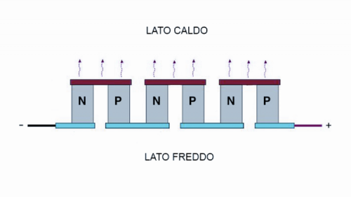
Layering junctions between two different metals arranged alternately (I.e. a metal between two slices of a different one) makes the so-called “thermopile”: when heating an end and cooling the other, you can generate a potential difference proportional to the temperature gradient and, closing the thermopile terminals on a load, you have an electrical current flowing.


fig1


The thermopile can also work in reverse: fed with an electric current, a junction gets heated and the other is cooled; this phenomenon is the Peltier effect, and explains the Peltier cell principle.

The cells can be constructed using metals, but the high thermal conductivity of such materials would lead to having small temperature differences between the hot and cold sides; for this reason semiconductors materials, having a much greater thermal resistance that better isolates the two junctions and increases the thermal jump, are preferred when building a Peltier cell.

The cell cooling capacity is always less than the electric power absorbed, because an important amount of energy is dissipated as heat; for this the Peltier cells are convenient only where the low energy performance is less important respect to advantages like compactness and fast required temperature reach.

That said, let’s see how the cooler is structured.


System layout

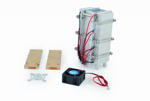
The refrigerating unit is made by two finned heat sinks on one side and plain on the other. The two heat sinks are laid face-to-face and enclosed laterally to be air-sealed (preventing fresh air leaks). On the flat parts, are mounted six 51W Peltier cells, connected in series as shown in the diagram in these pages. The two blocks of three cells are interconnected in parallel, so that we can power the device with a 36Vdc power supply.

We opted for the series-parallel connection, as it is a good solution to use a commonly available on the market 36V power supply, with a current that is not too high limiting thus the power leakage due to cable voltage drop. The three cells in series on each side require 36V (each cell needs 12V) and the two groups are fed in parallel with this voltage. Each row absorbs little more than 4 Amperes, and then 9.6 Amperes provided by our 36V power supply are enough for the whole system.

The Peltier cells cold side is coupled to the aluminum heat sink flat side by using metal screw clamps. The hot sides are coupled to two liquid cooling aluminum waterblocks: the liquid cooling is really efficient and we need it since the more heat we dissipate, the lower temperature we can reach on the cold side.


fig2


Each cooling coil is actually a parallelepiped with long faces flat and smoothed so to adhere perfectly to the Peltier cells heat exchanging surfaces. Two tubular fittings with conical arrowhead to lock rubber hoses are used for the hydraulic circuit.

To facilitate the heat exchange, it is better to use a thermal grease (as the one commonly used between CPUs and heat sinks) between the cooling coil and the Peltier cell.


fig3


In our design, since this choice does not intriduce particular problems but simplifies the connections, we connected the cooling coils hydraulically and thermally in series: one receives the incoming rubber pipe from the air/water intercooler and the first waterblock outgoing pipe is connected to the second cooling coil. The latter outgoing hose returns to the air/water intercooler.

Two independent bodies connected in series make this intercooler: a pipe connects the upper end of the lower body with the lower part of the upper; the rubber pipes connected to the intercooler’s in/outgoing fittings will be connected to the cooling coils free ends.

This hydraulic series circuit has the main drawback that the second cooling coils receives a liquid already warmed up by the first heat sink, but on the other hands helps us preventing air bubbles in the circuit, a common problem with parallel connected circuits.

A 12V 120×120 mm electric fan, enough to dissipate heat even in summer, cools each one of the intercooler two bodies.


fig4


Note that the water / air exchanger can also be single body. At the lower water inlet we have to mount a 12V electric pump, like the MINIPOMPA12V available on Futura Elettronica Shop (www.futurashop.it); it is a small and very light device, capable of a flow rate of 240 liters / hour, to push water to a height of 3 meters and protected, on the electrical side, up to IP68. The absorption is 400 mA.

The aluminum heat sinks block and the Peltier cells should be laterally covered (but also completely if you prefer) with insulating material, to waste less heat as possible.

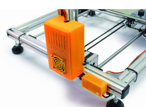
According to the proper system operations, the described body should be arranged vertically, with 40×40 mm fan on top aspiring the cooled air and sending it to the plastic conveyor. This conveyor is connected through a plastic hose to the special conduct put near the printing head of our Choco 3Drag.

The vertical mounting setup helps avoiding the condensing air humidity to be sprayed directly to the deposited chocolate: the water condensed on the intercooler (during the de-freezing process, that is managed by the controller and that we’ll describe in a while) will drop down, saving the fan (that is mounted on the upper end) and the printing plate.

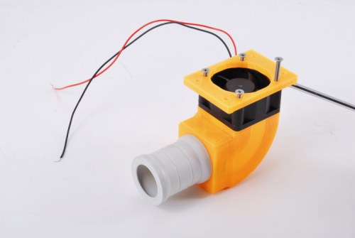
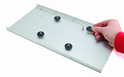
The fan blows the cooling air into a 3D printable plastic conveyor (print it with your 3Drag using these STL files); the conveyor is assembled on top of the 40x40mm fan with a plastic adapter (also printable in PLA with 3Drag starting from STL we provide) and ends with a tube coupling (like the one used for electrical systems) inserted and screwed (with its appropriate ring) in the upper plate, which is already drilled for the purpose. The 25mm junction, watertight (IP66) allows to apply the 25 mm diameter corrugated tube without flow losses.

The conveyor, complete with fan and connection is visible in figure.


fig5


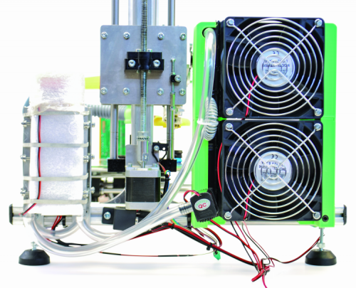
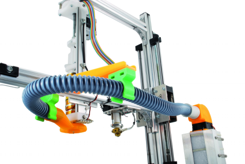
The cooler and the conveyor system is, fully assembled, as shown in figure . Since all the fans are 12 volts models, they are connected in parallel to a DC / DC converter that provides this output voltage. The converter is powered by the same 15 V DC power supply that powers the electronic control system.


fig6


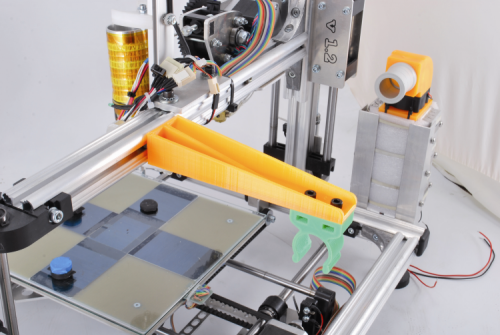
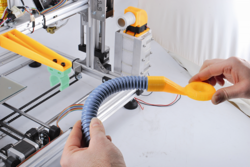
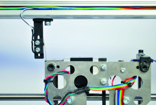
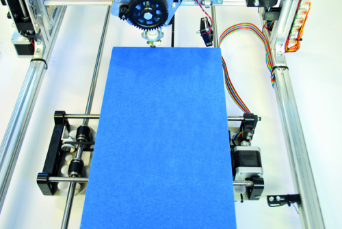
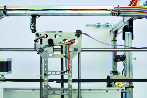
The corrugated tube that brings cold air directly to the extruder is long and not much flexible; since it must be bended, it needs to be supported by a dedicated arm mounted on the 3Drag horizontal profile (the same that holds the print head). Both these parts are printed with the 3Drag, starting from .STL file we provide (PLA is fine).

The arm is fixed to the printing head supporting aluminum bar with square nuts slid into the profile, then tighten with the bolts provided. The clip is screwed to the opposite arm end with 5MA bolts and nuts (there are apposite slots in the clip). The set is displayed in figure.


fig7


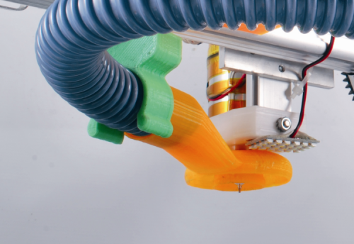
Made the mechanical assembly, we must connect one end of the corrugated tube to the special cold air vent, which is a sleeve (also printable in PLA with 3Drag) terminating with an open ring (“donut”) on the bottom to blow directly onto the melted chocolate.


fig8


This positioning arrangement, combined with the fact that the nozzle can be mounted in the inner hole of the donut, thus surrounding the printing head, helps us avoiding to insulate the outside of the latter. Once applied the corrugated tube other end to the conveyor located on the chiller group, the machine will be as shown in figure


fig9


fig10


The control unit

Let us now focus on the electronic control unit, which drives the cooler. It is the same 3Drag v1.2 printer controller, which uses the output for the heated plate (that for the Choco printing is not needed, since we need to cool the area…) to supply, through a 12V-30A relay, the Peltier cells circuit. We also use the FAN output (to be managed by the appropriate command in the printing client software) to control the 40x40mm fan. Of course, it is needed to upload the proper firmware to the ATmega2560 to have this control activated.

The firmware does not manages the cold air temperature, but, to prevent the icing of the condensing air humidity that can obstruct the duct between the heat sinks, we need to periodically switch the Peltier cells off. To do this, we can use the heated plate control available on Repetier-Host or on Cura printers for example. The ice on the heat sinks will melt and drop out on the radiators bottom.

The shut-off period shall be chosen according to your experience and to the air humidity percentage; clearly at the beginning you have to do some testing to take confidence.

Since the firmware is written to read the heating plate temperature through a NTC, we need to “deceive” the controller by connecting a 120KOhm resistance (0,25W) to the thermistor dedicated pins.

The printer connections scheme is the 3Drag original one, and since this project is supposed to be made on an already assembled and working printer, we will not repeat it here. What you need is the cooling system connection as we’ve already shown before. For the controller board and the DC/DC converter we imagine PLA boxes, printable with 3Drag (you can download the STL files).


fig11


Having closed the controller in a box, we have designed openings needed for the ventilation required by the driver modules, as well as a 12V 40×40 mm optional fan slot to cool the controller. The two containers are to be secured to one of the side sections of the printer with screws provided with spacers and nuts.


From openstore

3Drag – 3D printer – KIT

Extrude for chocolate


An ARDUINO based JPEG Camera with IR and PIR

$
0
0

 featured


Let’s equip Arduino with a serial-interface JPEG Camera with IR and try two applications: the first one saves shots (on a SD-card) at regular intervals while the second uses a PIR sensor to detect intrusions and photograph what happens.


Recently, miniaturized cameras with serial communication interface have been launched on the market. Compared to traditional cameras, they offer easier integration with Arduino or other microcontroller-based boards.

It is quite easy to understand that using a composite or USB interface camera requires a considerable effort, on both hardware and software sides. If you decide to bet on a serial interface camera, everything gets easier, because all the prototyping boards (Arduino in particular) and all microcontrollers (Microchip, Atmel etc.) have at least one serial port as a standard feature.

The basic concept of these cameras is that you can send all the setup commands, take screenshots and viewing images through appropriate bytes sequences via their serial port.

In our case, we will use a LinkSprite camera connected to Arduino Uno. Special feature of this camera is the ability to capture images even at night; in fact, it has a brightness sensor and infrared LEDs activated automatically when the detected light falls below a certain threshold (refer to the pictures in these pages to get an idea of how infrared LEDs work).

The camera is capable of capturing high-resolution images, sending them as JPEG through the serial port. It has a four-pin connector where two pins are for the power supply (+ 5V and GND) and two for the serial port (RX and TX).


figura B


This article will show how to use this camera in two different Arduino projects: the first creates a timing system to take pictures on specific intervals, storing them on the SD-card, while the second is an automatic surveillance system activated only if the special PIR sensor (Passive Infrared Radar) detects a warm object moving in the camera view field. In practice, this second application is a time-lapse video surveillance device that records what happens in a room, activated by the detection of moving people or vehicles. Of course, the PIR detection area must match the same camera angle so that the captured images effectively show the triggering “foe”.

Images will be saved on a Sd-card in JPEG format file and therefore we need a dedicated Sd-card shield (available on Futura Elettronica).

Finally, we will use software libraries (JPEGCamera) developed by us specifically for these camera usage examples.


figura C


SYSTEM HARDWARE

About the first application, the hardware consists of an Arduino Uno Rev 3 and a SD-card shield used to save images, all connected to the serial camera. The SD shield has four jumpers allowing us to choose which Arduino pin works as “chip select” (you can choose between D4, D8, D9 and D10); for “chip select” we mean the command line that enables the shield.

In our examples, we use D4 therefore we have to insert the corresponding jumper.

The camera has a four-pin connector used for both power and serial interface, and is supplied with a four wires cable (colors: red, brown, purple and gray) ending with female jumpers. Please note that for the serial communication between Arduino and the camera we decided not to use the hardware serial port, but we use the software one (mapped on Arduino D2 and D3 pins); in this way, the software library keeps the hardware port free for debugging.

To connect Arduino to the camera you need to connect the red wire (RXD) to Arduino D3 pin; the brown (TXD) to D2; the gray to the + 5V signal and finally the violet to ground (GND).

For the second application, we must add the PIR sensor to the hardware just described. What we used for our prototype is a device with a certain “intelligence” on-board, which implements two different trigger modes, providing a programmable delay time (between the motion detection and the signal trigger ) ranging from 0.3 to 180 seconds, has a 120 ° detection angle and  7 meters maximum range. The sensor has three pins (TTL 0V – 3.3V output and positive-negative power supply). To connect Arduino you must create a three-wire cable where the power supply positive and negative pins must be connected to Arduino +5V and GND while the TTL output to Arduino D5 pin. Through the output, the device sends the trigger signal caused by PIR sensor movement detection.


ARDUINO LIBRARY

JPEGCamera

figura A


To allow Arduino managing the JPEG camera we have developed a library (JPEGCamera) that offers all the LinkSprite camera functions: initialization, screenshots capturing and saving images.

The library provides an object called JPEGCamera you can call for complete hardware management.

Begin function initializes  the entire camera management system, a Reset physically resets the camera, a setImageSize  sets the captured image size (you can choose between 160 x 120, 320 x 280 and 640 x 480 pixels). Then there is the takePicture function , who commands the camera to capture the image currently framed (basically is the take screenshot function) and readJpegFileSize, which reads the size (in bytes) of the image file stored. Other functions include the readJpegFileContent, which deals with reading (a packet at a time) the image data and finally stopTakingPictures, which stops the screenshots capture.


figura 1

figura 2


The readJpegFileContent function deserves a special mention: the data reading process works with a packet (64 bytes, in our case) at a time. To do this it is necessary, each time you call the procedure, to indicate the starting address (the first time is equal to 0, the second 64, the third 128 and so on) and the packet size to be read (in our case, always 64; please note that it is not possible to exceed that value). The function requires as input a byte array where data will be saved; also returns the iSend output parameter, which indicates if the reading operation has been completed.


SKETCH EXAMPLE 1

Starting from the beginning, we analyze the first JPEG camera example code, the continuous saving images application (Listing 1).

We include the necessary libraries (JPEGCamera.h, SoftwareSerial.h – since we will use a software serial interface – and SD.h, to save images on the SD-card) and define the size (in bytes) of a single data packet stored (chunk_size; 64 bytes).

Subsequently we define the Arduino pin (D4) we will use as SD-card chip select and some variables that we will use in the program (in particular jpegCamera, used for camera management). Inside the setup function we initialize the board and we call the camera begin command; later we initialize the SD  library indicating that we want to use D4 pin as chip select.

In the loop function, we manage the real images capture and saving; first we set to capture 320 x 280 pixels pictures and through jpegCamera.takePicture we start capturing the single screenshot.

Afterwards we can define the “save as” filename (e.g. imageXX.jpg where XX ranges from 00 to 99) and through SD.open we can create and open the file in writing mode on the SD-card. Then, through a while loop we handle the image reading and saving process. With jpegCamera.readJpegFileContent we read one jpeg data packet at a time and we can save it by using the File object write function.

When the while loop ends, all the picture bytes have been read and saved; then we execute the File object close  function to close the file handler and jpegCamera.stopTakingPictures to tell the camera to stop capturing images.

Before ending the loop, let’s wait one second and increase the variable that counts the number of pictures taken.


 /*********************************************************************
* Inclusione librerie *
*********************************************************************/
#include <JPEGCamera.h>
#include “SoftwareSerial.h”
#include <SD.h>
// Chunk size per salvataggio immagine
#define CHUNK_SIZE 64
/*********************************************************************
* Definizione pin I/O Arduino *
*********************************************************************/
// Led scheda Arduino
const int pinBoardLed = 13;
// Pin Arduino Chip Select SD
const int pinSDChipSelect = 4;
/*********************************************************************
* Variabili programma *
*********************************************************************/
// Oggetto JPEG Camera
JPEGCamera jpegCamera;
// JPEG file
File jpegFile;
// Contatore immagine
byte i = 0;
/*********************************************************************
* Codice programma *
*********************************************************************/
// Inizializzazione Scheda
void setup() {
// Inizializzo I/O
pinMode(pinBoardLed, OUTPUT);
pinMode(pinSDChipSelect, OUTPUT);
// Accendo led Arduino
digitalWrite(pinBoardLed, HIGH);
// Inizializzo JPEG Camera
jpegCamera.begin();
// Init SD
pinMode(10, OUTPUT);
if (!SD.begin(pinSDChipSelect)) {
// Lampeggio led Arduino
for (;;) {
digitalWrite(pinBoardLed, HIGH);
delay(500);
digitalWrite(pinBoardLed, LOW);
delay(500);
}
}
// Spengo led Arduino
digitalWrite(pinBoardLed, LOW);
} // Chiusura funzione setup
// Programma Principale
void loop() {
boolean isEnd = false;
uint16_t address = 0x0000;
uint16_t chunkSize = CHUNK_SIZE;
byte body[CHUNK_SIZE];
// Imposto dimensione immagine
jpegCamera.setImageSize(jpegCamera.ImageSize320x280);
// Reset JPEG Camera
jpegCamera.reset();
// Scatto immagine
jpegCamera.takePicture();
// Identifico nome file
char fileName[12] = “image00.jpg”;
fileName[5] = ((i / 10) + 0x30);
fileName[6] = ((i % 10) + 0x30);
// Apro file
jpegFile = SD.open(fileName, FILE_WRITE);
// Leggo/salvo i dati immagine
isEnd = false;
while(isEnd == false) {
jpegCamera.readJpegFileContent(address, chunkSize, body, &isEnd);
address += chunkSize;
// Salvo i dati sul file
jpegFile.write(body, chunkSize);
}
// Chiudo file
jpegFile.close();
// Fermo immagine
jpegCamera.stopTakingPictures();
// Attesa
delay(1000);
// Prossimo file
i = ((i + 1) % 100);
} // Chiusura funzione loop


SKETCH EXAMPLE 2

The second example, besides implementing the functions explained in the previous example, manages a PIR sensor too and therefore can be used as an anti-intrusion detection system prototype.

The algorithm works as follows: cyclically Arduino saves images (max. 5 – image01.jpg, …, image05.jpg – overwriting the oldest cyclically) in a SD-card folder (DIR000, …., DIR999); when it detects an alarm condition the cyclical saving process continues but changing the filename to image06.jpg, …., image10.jpg and increasing the folder name number. Then, everything goes on as before.

The first lines of this software are the same as the previous sketch (libraries inclusion, saving process, Arduino pins definition and variables declaration).

The setup function is similar to that in Listing 1, modified to identify the first free directory (the folder number is indicated by the dirCount variable). Even the loop cycle is quite similar to the previous example; different parts are needed to handle the different folder and file naming during intrusion detection. 

In addition, the last function commands added, check if there is an alarm signal coming from the PIR sensor: if yes, the file saving mechanism explained above is executed.

The sketch of the application is in Listing 2.

/******************************************************************************
* Inclusione librerie *
******************************************************************************/
#include <JPEGCamera.h>
#include “SoftwareSerial.h”
#include <SD.h>
// Chunk size per salvataggio immagine
#define CHUNK_SIZE 64
/******************************************************************************
* Definizione pin I/O Arduino *
******************************************************************************/
// Led scheda Arduino
const int pinBoardLed = 13;
// Pin Arduino Chip Select SD
const int pinSDChipSelect = 4;
// Sensore PIR scheda Arduino
const int pinPIRSensor = 5;
/******************************************************************************
* Variabili programma *
******************************************************************************/
// Oggetto JPEG Camera
JPEGCamera jpegCamera;
// JPEG file
File jpegFile;
// Contatore directory
int dirCount = 0;
// Contatore immagine
byte fileCount = 1;
boolean flagSensorePIR = false;
/******************************************************************************
* Codice programma *
******************************************************************************/
// Inizializzazione Scheda
void setup() {
// Inizializzo I/O
pinMode(pinBoardLed, OUTPUT);
pinMode(pinSDChipSelect, OUTPUT);
pinMode(pinPIRSensor, INPUT);
// Accendo led Arduino
digitalWrite(pinBoardLed, HIGH);
// Inizializzo JPEG Camera
jpegCamera.begin();
// Init SD
pinMode(10, OUTPUT);
if (!SD.begin(pinSDChipSelect)) {
// Lampeggio led Arduino
for (;;) {
digitalWrite(pinBoardLed, HIGH);
delay(500);
digitalWrite(pinBoardLed, LOW);
delay(500);
}
}
// Identifico prima directory libera
for (;;) {
char dirName[7] = “DIR000”;
dirName[3] = ((dirCount / 100) + 0x30);
dirName[4] = (((dirCount % 100) / 10) + 0x30);
dirName[5] = ((dirCount % 10) + 0x30);
// Se directory non esiste
if (SD.exists(dirName) == false)
break;
// Prossima directory
dirCount++;
}
// Spengo led Arduino
digitalWrite(pinBoardLed, LOW);
} // Chiusura funzione setup
// Programma Principale
void loop() {
boolean isEnd = false;
uint16_t address = 0x0000;
uint16_t chunkSize = CHUNK_SIZE;
byte body[CHUNK_SIZE];
// Imposto dimensione immagine
jpegCamera.setImageSize(jpegCamera.ImageSize320x280);
// Reset JPEG Camera
jpegCamera.reset();
// Scatto immagine
jpegCamera.takePicture();
// Identifico prima directory libera
char dirName[7] = “DIR000”;
dirName[3] = ((dirCount / 100) + 0x30);
dirName[4] = (((dirCount % 100) / 10) + 0x30);
dirName[5] = ((dirCount % 10) + 0x30);
// Se directory non esiste
if (SD.exists(dirName) == false)
// Creo directory
SD.mkdir(dirName);
// Identifico nome file
char pathComplete[22] = “DIR000/image00.jpg”;
pathComplete[3] = ((dirCount / 100) + 0x30);
pathComplete[4] = (((dirCount % 100) / 10) + 0x30);
pathComplete[5] = ((dirCount % 10) + 0x30);
pathComplete[12] = ((fileCount / 10) + 0x30);
pathComplete[13] = ((fileCount % 10) + 0x30);
// Apro file
jpegFile = SD.open(pathComplete, FILE_WRITE);
// Leggo/salvo i dati immagine
isEnd = false;
while(isEnd == false) {
jpegCamera.readJpegFileContent(address, chunkSize, body, &isEnd);
address += chunkSize;
// Salvo i dati sul file
jpegFile.write(body, chunkSize);
// Se sensore PIR non rilevato
if (flagSensorePIR == false) {
// Se sensore PIR attivo
if (digitalRead(pinPIRSensor) == HIGH) {
// Prossimo file è il 6 (verrà incrementato in seguito)
fileCount = 5;
flagSensorePIR = true;
}
}
}
// Chiudo file
jpegFile.close();
// Fermo immagine
jpegCamera.stopTakingPictures();
// Attesa
delay(100);
// Se sensore PIR non rilevato
if (flagSensorePIR == false) {
// Se sensore PIR attivo
if (digitalRead(pinPIRSensor) == HIGH) {
// Prossimo file è il 6
fileCount = 6;
flagSensorePIR = true;
}
// Se sensore PIR non attivo
else {
// Prossimo file number
if (fileCount == 5)
fileCount = 1;
else
fileCount++;
}
}
// Se sensore PIR rilevato
else {
// Se salvati 5 file
if (fileCount == 10) {
// Resetto file
fileCount = 1;
// Prossima directory
dirCount++;
// Indico reset PIR
flagSensorePIR = false;
}
else
fileCount++;
}
} // Chiusura funzione loop


From store

PIR motion sensor

SDcard shield for Arduino

JPEG Color Camera Serial Interface

Arduino UNO R3


VOCAL CONTROL

$
0
0

easyv3-assembly

In this guide, we will describe how the DM Board ICS outputs can be controlled by means of your own voice. Here you can view a demonstration video.


Hardware

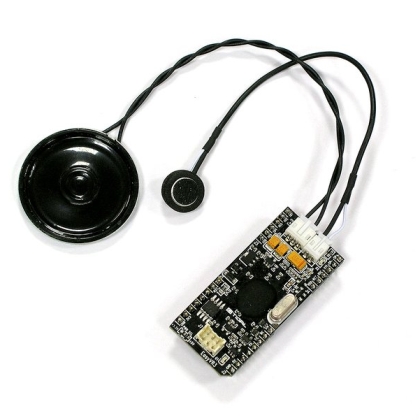
The module EasyVR 3 made by VeeaR  is the speech recognition system chosen for this project.

The connection of this module to the DM Board ICS is very simple. There are only three steps to be made (see the image):

  1. Connect the microphone (provided with the module) to the EasyVR 3.
  1. Connect a loudspeaker (not included in the module) using the provided cable.
  1. Connect the module to the DM Board ICS using 4 wires: 2 for the power and 2 for the serial interface.


1m


The EasyVR 3 module is pre-configured to work using 5V. As the DM Board ICS works at 3.3V, a resistor (that works as a jumper) have to be moved to make the module work at 3.3V as well:


2


A simple relay, connected to an output of the DM Board ICS, allows driving a 220Vac lamp.


Software

The first step is to program the DM Board ICS with the application software (Controllo Vocale) that can be downloaded from the DM Store. It allows to control the EasyVR 3 module.

Once the software is loaded into the DM Board ICS it is necessary to program the EasyVR 3 module with the required vocal commands.

The EasyVR 3 programming software can be downloaded here.

It is possible to program the speech recognition module by means of the USB port of the DM Board ICS by putting the board in USB-RS232 bridge mode (so that all the signals coming from the USB port are directly routed to the EasyVR 3 module).

The bridge mode can be enabled by pressing the SW1 button of the DM Board ICS after powering the board (just after the beep signal and within 3 seconds). The button must be kept pressed until the DM Board ICS emits a second beep signal (that confirms the bridge mode activation).

The first step, after launching the EasyVR 3 programming software, is to connect the software to the module by pressing the connection button:

On the left side of the programming software there are several command groups. The ones required are:

  1. Trigger:
    Contains the words that wake up the VR module (In our case “Ciao DM Board”)
  1. Group 1:
    Contains the command words we want to enable (In this example “Accendi” e “Spegni”)
  1. Sound Table:
    Contains the phrases that the module has to play in response to the trigger and the commands (“Ciao, pronuncia il commando desiderato”, “Accensione in corso” and “Spegnimento in corso” in this application).

The module EasyVR 3 has two recognition modes:

  1. Speaker voice dependent:
    The module only recognize the voice of a specific person. This mode requires to pre-record into the module the commands using a simple procedure.
  1. Speaker voice independent:
    In this mode the module recognize the commands regardless of the speaker. However to enable this mode the QuickT2SI software is needed and this software is not free to use (it requires a license). We used of course the first approach.

Several .wav audio files (16bits 22050 Hz), one for each phrase that we want to be played by the VR module and one for each commands, are required. The open source software Audacity (http://audacity.sf.net) can be used to generate those files.

For more details on the EasyVR 3 module programming please refer to the manual.

When the module recognizes a command, it sends a code that correspond to the position of the audio file in the group. In this example, we loaded in the 1st position of the “Group 1” group the “Accensione” command audio file and in the 2nd position the “Spegnimento” command audio file.

The very same mechanism works also for the phrases that the module has to play in response to a command. We loaded in the 1st position of the “Sound Table” group the “Ciao, pronuncia il comando desiderato” audio file, in the 2nd position the “Accensione in corso” audio file and in the 3rd position the “Spegnimento in corso” audio file.

Adding Internet connectivity to Arduino boards and apps with the YUN Shield

$
0
0

What if we have already developed an Arduino application and we want internet connectivity for it?
Yun shield is the answer.


Yun shield provides Internet connectivity for all Arduino boards. It features the same connectivity functions implemented on Arduino Yun. Yun shield runs the OpenWrt GNU / Linux operating system, specially designed to manage internet connectivity. It’s the same on Arduino Yun and is commonly used by open source software equipped Access Points. Well, why Yun shield and not Arduino Yun itself? Simple, the shield can be connected to different Arduino boards, giving the opportunity to connect online our already developed applications, offering them new interoperability and remote applications. 


Fig1


Obviously it is possible to use it in new applications for which you want to adopt a different module than Arduino Leonardo. Among the Arduino boards compatible with Yun shield, we have Arduino Uno, Duemilanove / DIECIMILA, Arduino Mega and, of course, Arduino Leonardo, as well as several others. Another pleasant surprise is the ability to adapt both to 5V and 3.3V port voltage levels according to the different modules it is matching to. Among other peculiarities, a WiFi antenna is included in the package, helping you to establish particularly stable WiFi connections in various conditions.


System Architecture

In the block diagram, you can see how Yun shield connects to hosting boards. The host board powers the Yun shield through the VIN pin. It uses both the UART connection (Bridge library) to communicate with the module it is inserted on and the SPI connection to program Arduino, with its IDE connected via TCP / IP.

The “heart” of Yun shield is based on Atheros AR9331 processor, widely used in WiFi connectivity solutions (also in Arduino Yun). It has various interfaces such as Ethernet, USB, UART, and various GPIO peripheral devices. Supports 802.11b / g / n 2.4 GHz WiFi standard up to 150Mb. As said before, the operating system is OpenWrt, a GNU / Linux open distribution especially dedicated to WiFi connectivity and routing. RJ45, WiFi, USB Host and Failsafe are connected directly to the Dragino HE module. Dragino HE uses UART and SPI ports to communicate with Arduino. Yun shield is compatible with 3,3V and 5V powered Arduino boards. 

To set the right port working voltage, you need to act on SV1 jumper. The SPI interface is used only to load a sketch from the IDE to the board. Once you finished loading the sketch, the SPI interface is released and can be used to connect to other devices. The UART interface is locked by the Bridge library. As for Arduino Yun, even on Yun shield the Bridge lib is the heart of the communication link between the Atheros AR9331 processor (running OpenWRT) and Arduino microcontroller, so the UART interface can not be used by other applications. 

The working principle of the Yun shield – Arduino microcontroller link is fully described in the book “Discovering Arduino Yun”.  


Specifications

  • CPU: ATHEROS AR9331 processor, 24K MIPS@400MHz;
  • RAM: 64MB;
  • Flash Memory: 16MB;
  • Operating System: customized Open Source OpenWrt;
  • Power supply: 5V from VIN Arduino pin;
  • An RJ45 Ethernet 10M / 100M;
  • WiFi: 2.4Ghz, 802.11 b / g / n, 150M;
  • I-PEX connector to connect the internal antenna included in the package;
  • A USB 2.0 host connector, used to connect a USB stick or a 3G dongle;
  • A multifunction button (labeled Failsafe);
  • Compatible with the UART and SPI 3.3V and 5V voltage levels.


LEDs

On the shield, there are four LEDs with the following functions:

  • PWR: Power LED. It lights up when the shield is on;
  • LAN: is on or flashing to indicate the presence of a network connection;
  • WLAN: Indicates a working WiFi connection;
  • SYS: Indicates the presence of an USB memory. When lit, it indicates that the folders on the USB mass storage device are mounted on / mnt, /mnt/sd and /www/sd respectively.


Fig2 


Multifunction button

On Yun shield there is only one button, labeled “Failsafe”, to manage the reset and restore operations, which may be necessary sometimes. When the shield is on, after the boot process is over, holding pressed the failsafe button for 5 seconds resets to factory settings the WiFi chip configuration. 

Holding it for 30 seconds sets the whole shield to factory setting. The third use of the failsafe button is to initiate the board recovery function in case of wrong firmware upgrade. This process is very complex and too long to describe it in this article. The recommendation that we can give is to upgrade the firmware carefully to avoid being with the shield unusable. In any case the “rescue” instructions can be found at http://www.geeetech.com/wiki/index.php/YUN_SHIELD.


Power modes

A major issue when using Yun shield is how the power it. The shield is powered through GND and VIN pins. The recommended way is to use these pins. The Dragino HE module, which is the heart of this shield, requires a 200 mA current at full load, so it is a best practice to connect it to the pins said before rather than overheating the 5V LDO (low drop out) power supply module. In this configuration, it is better to power Arduino through its DC connector and not by the USB port. Be careful to use an external power supply providing more than 7V input voltage.


 1213_Schema


Using the Yun shield with Arduino modules

To take advantage of all the opportunities offered by Yun shield we need to do a preparatory work both for the boards that we want to connect and to adapt the Arduino IDE to work with different combinations of modules. 

The Yun shield uses the SPI port to load sketches and the UART serial port to communicate, using the Bridge library, with the microcontroller it is linked to. For further information on Bridge lib refer, once again, to the quoted paper. In order to establish the communication link between shield and module you must check the following:

  • The Arduino module must be powered by the DC connector and not by the USB connector;
  • The jumper of SPI and UART voltage levels must be set properly;
  • The right “shield – Arduino module” coupling must be properly configured in IDE settings (we’ll see later on how to do it).
  • The UART and SPI ports must not be used by other programs;
  • Make sure that the “Linux Console / Arduino Bridge” mode is set (in “Sensor >> PowerUART” menu on the configuration tool)


Connect the shield to Arduino UNO

On Arduino UNO the UART serial connection between mega328P and mega16u2 microcontrollers interferes with the Bridge library functions used to communicate with Yun shield. 

You must disable the UART connection by configuring the microcontroller mega16u2 in “reset”. In practice short-circuit the pins shown in figure with the yellow jumper included in Yun shield package and power the two boards using the DC plug on Arduino UNO. 


Fig3


Note that with this configuration you can no longer connect Arduino to a pc via the USB port. For programming and debugging, you need to use the WiFi connection by choosing the “Arduino UNO – Dragino Yun” board on the IDE boards list.


Connect the shield to Arduino Mega2560

Even in Arduino Mega2560 the UART serial connection between the mega16u2 and Mega2560 microcontroller interferes with the Bridge library. You must disable that connection by configuring the microcontroller mega16u2 in “reset”. 

In practice short-circuit the pins shown in figure  with the yellow jumper included in Yun shield package and power the two boards using the DC plug on Arduino Mega2560. 


Fig4


Note that with this configuration you can no longer connect Arduino to a pc via the USB port. For programming and debugging, you need to use the WiFi connection by choosing the “Arduino Mega2560 – Dragino Yun” board on the IDE boards list.


Configuring Yun SHIELD

The Yun shield has both the WiFi module and the Ethernet LAN interface onboard, which can be used either for an internet connection or for system administration. The Yun shield can operate autonomously: just plug it in to have a network access point. For the first test we chose to mount it on an Arduino Uno, connecting the small antenna included in the kit, setting the Dragino HE jumper configuration to accept a 5V supply voltage and powering it by the Arduino Uno DC “barrel” connector. A 7.5V input voltage is recommended.


Fig5


At boot time the Yun shield, as default configuration, shows off as an access point with a SSID named “Dragino-xxxxxx”, where “x” stands for the shield MAC address. The first time connection procedure is similar to that required for Arduino Yun. Using a PC with WiFi, connect to the shield WiFi SSID (password not required) then open a browser and type the address 192.168.240.1. This method works perfectly if the PC network card is set to DHCP mode, receiving its address from Yun.

If everything went smooth, the configuration tool LuCI will be open in the browser page (we recommend using HTML5 compliant browsers, like Firefox and Chrome). You can alternatively connect via SSH using tools as Putty, WinSCP or MobaXterm, all instruments whose use has been extensively described in previous posts. Or you can type the shield host name “dragino.local” in browser URL bar: if this does not work, type the shield IP in address as told before (if YUN is our default access point it’s 192.168.240.1). If, instead, we are connected to Yun via a wired network, we must know the IP address assigned by DHCP. 

Failing that, the system has a pre-configured fallback address, 172.31.255.253 with network mask 255.255.255.252 (pay attention to the final 252). This way you can connect the shield with a network cable, setting on your PC the IP address 172.31.255.253 (always with network mask 255.255.255.252). 


Fig6


Whichever way we connect, we will open the login page of the configuration tool. You access the configuration tool by entering “dragino” that is the password of the only (default) user, “root”. We get the active network interfaces configuration page. This page tells us that the network interfaces are preconfigured and a web server is already installed with an application that allows you to configure those parameters.


Fig7


Always in the page we see the board WAN IP address (if connected through the network cable), and the WiFi section configuration (by default active and pre-configured as an access point with its own static IP). 


Fig8


On page top right, we have the buttons to access the three main system configuration sections: “SYSTEM”, “SENSORS” and “UPGRADE”. Click on “SYSTEM”, which will open the SYSTEM configuration section, similar to Arduino Yun and Linino one. On this page we configure the correct Time Zone (Europe / Rome), and select the “Open” check box in the “Rest API Access”. We confirm the settings by clicking the big “CONFIGURE & RESTART” button and wait for the system reconfiguration, which takes a few minutes.


Fig9


We reconnect to the shield, then click on the “advanced configuration panel” button and enter the administration panel. From the top menu pages, we can access all the different sections.


Fig10


If we go to “Network” and “WIFI”, click on “Edit” button and scroll down the page we find the section to configure the interface in different modes (Access Point, Client, Ad Hoc, etc.). Other configuration sections allow us to set access security (Firewall), static routing, DHCP and DNS.


Fig11


So, we have a powerful device that allow us to solve any connectivity demand from a wide range of applications. 

One last thing, let’s try to connect to the board by using the SSH clients PuTTY and WinSCP (for those wishing to learn more about what has been said so far, including most of the configuration pages, refer to the introductory Raspberry Pi articles and the book “My first Linux embedded”). 


Fig12


We connect to Yun shield IP address, login with “root” user (password “dragino”). So we are sure that SSH server is up and running “just out of the box”.


Fig13


Firmware Upgrade

We anticipate this section since it is better to update the shield firmware release before starting with our application. The reason is mainly the many changes made ​​to the “SENSORS” section, which had many design changes over the releases. Initially designed to facilitate sensors data collection and processing through dedicated services as Xively, it was then modified to configure the Arduino board type the shield is housed in. 

Firmware versions can be checked at:

http://wiki.dragino.com/index.php?title=Yun_Firmware_Change_Log

The different firmware releases can be downloaded at:

http://www.dragino.com/downloads/index.php?dir=motherboards/ms14/Firmware/Yun/

Before continuing, we recommend to perform the firmware update process very carefully, double-checking every step. Take all the necessary time, the operation takes a long time so be sure to have a stable network connection and a reliable power source.

As a first step, you need to download the firmware. Go to “Download”, click on “Newest Firmware” and finally on “common-build-xxxxxxxx”. Attention: depending on the release, these guidelines may not be completely accurate. In the online folder, we see some firmware images. You have to download the “sysupgrade” (with .bin suffix) version. Download and save it on your PC. 

After, go to shield configuration page and click on “UPGRADE”. On this page, you can select the firmware to use for the update. A recommendation: remove the check mark on “Keep Settings”. 


Fig14


By doing so, the update has the disadvantage of resetting any pre-existing system configurations, but guarantees from misalignments between the existing configuration and the new version setting files. A misalignment coud “block” the shield after a firmware update. 

With the “Browse” button, select the file you just downloaded. Is it all OK? Recheck. Then click on “Upload Firmware”.


Fig15


Now let the system completing the update operation, which takes several minutes. Without touching anything, just watch the yellow LEDs on the shield.

They are flashing in various ways. Before trying to reconnect, wait for the LEDs to be turned back stable on. Pay particular attention to the WiFi chip activity led, since this chip is the last to boot up. Done? Is it all OK? Connect back to the shield.


Fig16


Sensors

The “Sensors” section presents different features depending on the firmware release installed. If you have installed the latest release, opening the page you can select the Arduino model you are connecting to (typically, it is automatically recognized). This is a configuration step not needed on Arduino Yun and Linino, but for the shield it is necessary to correctly configure the settings to be used when uploading the sketch (as MCU type, bootloader, fuse).


Fig17


A nice feature on this page allows you to upload directly a .hex file. This avoids every time the sketches compilation process and also doesn’t force you to open the IDE just for the uploading. A function in the “SYSTEM >> advanced configuration panel >> Sensor >> Microcontroller” menu allows you to automate the sketch upgrade at every boot. The presence of this setting in different sections of the configuration tool and the frequent release of firmware updates tells us that YUN shield is a growing product, wanting to a proper place in the Internet of Things. Now we can only judge positively this condition.


Fig18


Programming

The Yun shield, or rather the “shield and Arduino” group is programmed by using the Arduino IDE. First, you need to customize the IDE to have it recognizing and managing the various combinations of modules and shields. 

We have already mentioned that we can download the Arduino Yun IDE from Arduino official site. For our tests, we decided to use the latest version (1.6.3). This release is particularly suitable to be customized through third-party components, making it easy to be used with “compatible” boards and modules. We chose the portable version that requires no installation (.zip file). Just unzip it in a dedicated folder. We create a desktop shortcut to “arduino.exe”. To customize the Arduino IDE we have to download the necessary software from the GitHub repository https://github.com/dragino/modules (where you can download the full .zip library, then unzip it in a folder). Inside the folder, find the “modules-master \ hardware \ YunShield \ sketchbook \ hardware \ YunShield” subfolder and copy it to “Arduino_1_6_3 \ arduino-1.6.3 \ hardware”. 

Connect the PC to the shield by using the WiFi connection, as said before. Run the Arduino IDE. In “Tools >> Listing” menu choose the right configuration, “Arduino Uno – Dragino Yun” in our case. 


Fig19


Then, under “Tools >> Port”, select the TCP / IP connection that shows the right shield IP address.


Fig20


If you do not see the connection between shield and PC, open an SSH connection with PuTTY and run the command:

/etc/init.d/avahi-daemon restart

Thus forcing OpenWrt to broadcast its network service availability. If the shield is not detected yet, repeat the command. It may happen that, despite everything, you still do not see the board. In this case, we have to know that the connection daemon uses the 5353 UDP port. The cause of the issue may be a firewall, for example, or the antivirus, or a wrong router configuration, which blocks that port. For those wishing to further deepen this topic, always refer to the book mentioned above. 


Fig21


Fig22


Now, to prove that everything is working properly, we can try to load a sketch. We chose the “Console Read” sketch that allows us to test the “bridge” between Arduino and Yun shield. The sketch is accessible from File >> Examples >> Bridge >> Read Console. Compile and load it as usual, then at the Upload password prompt enter “dragino”. Open the Arduino IDE serial monitor “Tools >> Serial Monitor”. Set the communication speed to 115200 baud. A simple interactive application will be displayed.


Fig23


From openstore

YUN Shield for Arduino Uno and Arduino Mega

Arduino UNO R3

ARDUINO MEGA2560 REV3

Presepino: the nativity scene with Arduino

$
0
0

presepino featured


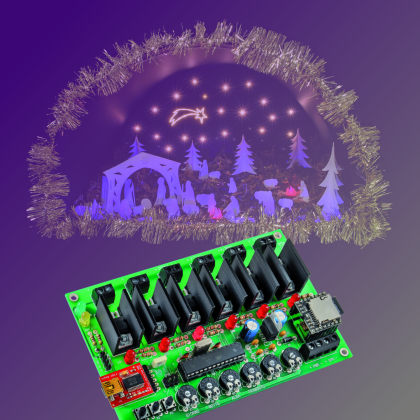
A light system, capable of simulating the alternation of night and day, that will make your nativity scene – be it a small or a big one – even more realistic. Our circuit is capable of piloting four light loads, corresponding to the daylight, to the brilliance of the stars, to the household hearths, and to the guiding star. It allows the control of LEDs and of a NeoPixel strip.

As with every year – with Christmas time approaching – we think about a themed project that might be able to make it even more original and warm. We decided to opt for a nativity scene control box, but we deemed right to make it in a modern and topical key; and with “topical” we mean the usage of hardware that has been experienced and appreciated, that is what thousands of experimenters could find in Arduino. This Presepino was born, that is to say, a light and sound control box for nativity scenes, whose circuit is based on the ATmega 328 microcontroller (therefore, that’s Arduino UNO’s hardware) and created so to directly command some LEDs, with all the relevant advantages: the first among all of them is the fact that it operates at a low voltage, and therefore it may be placed in the vicinity of children, without any danger for their health. Moreover, with LED strips being greatly available nowadays, it turns out to be very easy to create an automated nativity scene.

In addition to the lights, our Presepino enables the audio management, thanks to an innovative MP3 player module, mounted on the board, and capable of reproducing (even if in mono sound) all the tracks contained in a SD-Card.


The project

But let’s go in order and see – as a first thing – all the available functions, that differentiate our control box from those used for the simple control of two lights: dawn and sunset. With Presepino it is possible to obtain a control going beyond the one needed in small or big nativity scenes found in the houses, and one that is suitable for the nativity scenes prepared for the churches, for the parish youth clubs, for the community centres, and more in general for the places of worship. For this reason we created a circuit that is certainly a powerful one, and capable of driving four light loads, having LEDs operating at 12 volts and absorbing an individual power of 6 amperes; this is also the maximum current that the board may manage, and it can be powered by copiously tinning the tracks going from the power terminal box to the MOSFETs, and from the latter ones to the corresponding output terminal boxes. With “individual current” we mean that each channel may commute 6 amperes, but given the way the printed circuit board has been built, it is not possible to constantly absorb 6 amperes from all the outputs at the same time. These values, considering that the circuit was born for the purpose of piloting LED strips or – anyway – LED compositions, are more than adequate ones, and for a home nativity scene they are more than abundant.

The outputs for the terminal box are six, but the firmware we supply contemplates the management of the first four, so to implement the simulation of the daylight, of the starlight, of the hearths for (Bethlehem’s) hut/cave and for the shepherds’ houses, and finally of the guiding star’s lighting. The lights are progressively turned on and off, and follow a cycle that simulates the duration of the whole day.

To these basic outputs you may add the other two, by acting on the sketch for the ATmega 328 microcontroller: to them you may assign the control of various accessories in the nativity scene, such as a paddle wheel, the movement of animated characters or animals, and so on.

As regards the basic outputs, we divided the complete sequence in four phases, obviously named day, sunset, night and dawn. The duration of each phase may be independently adjusted; as for day and night, the duration is set between about 3 and 10 minutes, while the two transitions have a duration between about 20 and 100 seconds. Obviously the latter ones are the most evocative ones: during the sunset the day luminosity (SOLE output) gradually decreases, while the stars start to light up (STELLE output); at a certain point, before the cycle reaches its conclusion, the hearths in the houses and in the hut will light up (FUOCO output). By the way, our circuit is capable of simulating the flickering flames of the wood burning, by piloting the FUOCO output, by means of an appropriate sequence of pulses. When all the stars in the sky are completely lighted up, even the guiding star will appear (lighted by the COMETA output). Obviously, and except for some small details, during the dawn all the other lights will gradually turn off, while the “daylight” will reach the maximum luminosity.

The two auxiliary outputs are OUTEX1 and OUTEX2.


Circuit diagram

Let’s get down to details now, by analyzing the circuit, that is based on the ATmega 328 microcontroller, on which the dedicated sketch is running: the latter implements the control of the outputs and of the module implementing the nativity scene’s sound, and that at the initialization sets PB0 as the output used for sending the serial commands to a possible Neopixel strip, and PB1, PB2, PB3, PD3, PD5, PD6 as outputs for the control of the MOSFET outputs to channel N (the transistors are some sturdy STP36N06s, having an Id of 36 ampere and a Vdso of 60V) that materially commute the power to the corresponding LEDs or LED strips. Each one of the microcontroller’s lines that are used in order to manage the outputs also pilots its own MOSFET’s gate, by means of a 1 kohm resistor; and between the gates and ground some LEDs are applied: they allow, by lighting up, to monitor the state of the corresponding transistor. Each one of the outputs supplies rectangular TTL-compatible pulses, that have constant frequency and are width modulated, by means of the PWM technique: this enables the variation of the average value of the voltage applied by the MOSFETs to the loads related to them, and consequently, of power and luminosity. This is carried out with a very high efficiency, since the MOSFET’s electrical resistance while in ON state (fully conductive) is a very low one and thus the dissipated power (the power transferred being equal) is a very limited one, if compared to the one that would come from a series piloting that uses DC voltage, in which the transistor would have to take upon itself the difference between the power supply voltage and the one applied to the load.

The current circuital configuration takes into account to power the LED strips by connecting their positives and negatives respectively to the + and – of the corresponding output. However, since the MOSFETs may “withstand”  up to 60 volts of drain-source voltages in the interdiction, it may be conceivable to start from an external power source even at 24÷36 volt of direct current, so to decrease the absorption (the electric power managed being equal). If the power is not taken from the circuit, the LED strip will have to be connected, with the + going to the chosen power supply’s positive and the – going to our control box’s output, it being understood that the power supply’s ground and the board’s one must be joined.


1230_Schema


We previously claimed that the complete sequence that is generated by our circuit is composed of four phases (day, sunset, night and dawn), whose duration may be independently regulated by means of the dedicated trimmers, that are connected to a potentiometer and powered at 5V, and whose pointer’s voltage is read by a microcontroller’s I/O, which is configured as an input and acquired by means of the A/D converter that is found within the ATmega microcontroller. In our project, the ADC is assigned to the PC0÷PC5 lines, with which the voltages of the six trimmers (that is to say, R1, R2, R3, R4 for the said functions, and R5 and R6 for the functions that we will assign to the optional outputs – respectively being OUTEX1 and OUTEX2 – that supply PWM signals, exactly as the four basic ones do) are acquired via scan. For the way the firmware has been structured, the duration of the respective cycles is directly proportional to the voltage applied to the corresponding trimmer, thus – for example – by bringing R1’s pointer towards ground, the duration of the day is reduced, while it is instead increased by bringing it towards the 5V’s positive. The PWM signals are generated by the PWM modules that are internal to the microcontroller, opportunely set by the firmware for each output.

Please pay attention to a detail: while the trimmers R5 and R6 directly control the PWM of the OUTEX1 and OUTEX2 outputs, in the sense that they directly act on them, the other four determine the cycles’ times and don’t do it directly for the duty-cycle of the PWM signals to the SOLE, STELLE, COMETA and FUOCO outputs; the PWMs and their periodicity are managed by the firmware’s subroutines (the ones dealing with the four phases, whose functioning depending on the time is defined by the voltages supplied by the R1, R2, R3, R4 trimmers). This functioning is a logical one, since the described phases involve more than one output and, in the case of the day/night transition, they specifically involve the SOLE and STELLE outputs, that fade out – as it is also with the night/day passage.

The trimmers from R1 to R4 are thus needed in order to manage the duration of the day (R1), of the night (R2), of the dawn (R3) and of the sunset (R4). The LD6 LED is briefly turned on when passing from a phase to another one.

The duration of each single phase is set by means of the dedicated trimmer; the maximum duration of each phase is of about 100 seconds; for the sake of precision, the duration is obtained by the ADC reading on 10 bits (between 0 and 1.023), considered in milliseconds and multiplied by 100 by the firmware. If you want different times, you may edit the sketch in the section dealing with the determination of the functioning on the basis of the time.


Listing1

if(runtime>time_trim+200){
for (int i=0;i<6;i++){
trimvalue[i]=(ReadTrimmer(i));
trimvalue[i]=trimvalue[i]*100;
delay (1);
}
time_trim=millis();
}
int ReadTrimmer (int id){
return(analogRead(trimmer[id]));
}


Listing2

void gestAudio(int track){
digitalWrite (LEDPLAY,LOW);
if (playing==true){
digitalWrite (LEDPLAY,HIGH);
track++;
if (track==5) track=1;
if (stopVol==false){
if(runtime>time_volume_running+200){
if(startVol==false){
if (volume>3) {
volume=volume-3;
Serial.print(“dec “);
Serial.println(volume);
}
else
{
playtrack(track);
startVol=true;
}
}
else
{
if (volume<(trimvalue[TRIMMER_VOL]/3500)) {
volume=volume+3;
Serial.print(“inc “);
Serial.println(volume);
}
else
{
startVol=false;
stopVol=true;
Serial.println(“finito ciclo”);
}
}
time_volume_running=millis();
setvolume(volume);
}
}
}
}

As for the other two trimmers, they can be customized via firmware and, in particular, R5 is free  while at the moment R6 has been used so to manage the audio playback volume.

Both some LED strips and some low power 12V lamps may be connected to the MOSFET outputs, and the same goes for single LEDs, electric motors (so to activate wheels or other mechanisms), as well as pumps (so to move the water in a small lake or river), and everything that the imagination may suggest, in order to create a nativity scene that looks “alive”.

To stay on the topic of the outputs, it is the case to talk about the one dedicated to the control of the Neopixel LED, that allows to add further light animations, such as – for example – a comet tail. The NeoPixel strips are managed in parallel, with a single Arduino line, that in our case may be easily adjusted at leisure, by specifying it in the sketch; the communication is a one-directional one, and manages a group of LEDs, that in our case are 24 overall.

The connection on the whole is illustrated in these pages, by the wiring diagram.

Before going on, it is appropriate to say a few words on the subject of the NeoPixel technology, since it enables the creation of “smart” RGB LEDs having controllers aboard, and that can be easily integrated in the Arduino environment, thanks to proprietary libraries that Adafruit makes freely available. A peculiarity of the NeoPixel LEDs is that they may be connected in cascade, so that the data line goes from one to the next one; the price to be paid is that, after a certain number of LEDs, the management speed has to be substantially decreased; because of that, if one has to create matrices – so to show some fast graphics – it is needed to use many lines, each one with only a few LEDs. But this kind of limitation does not concern our project.

Each RGB LED can be individually managed by means of a dedicated command (included in the serial string), and it may create up to 256 tones of its own colour, thus determining a total of 16,777,216 colour combinations. In practice, Neopixel is a solution that takes into account the integration of a driver and of its corresponding RGB LED in a SMD case, thus enabling a direct command for each LED.

The data channel used for the communication with the NeoPixel LEDs, and thus with the strips, is similar to the one used by the oneWire kind. The power supply provided for the NeoPixel LEDs is a 5 volt one; the communication is carried out at a maximum of 800 kbps.

For each LED strip it is possible to set the refresh frequency at leisure, so to make certain tricks of the light imperceptible. In our case, the LEDs’ scan frequency is 400 Hz for each strip.


presepino 4


More strips can be connected in cascade or in parallel, so to create different effects, but in this case such a configuration does not concern us; however please consider that the more strips are connected to a single data channel, the more the refresh frequency will be limited (the maximum data-rate value allowed being equal). Briefly, the refresh frequency, and thus the speed for turning on and off the single LEDs, is inversely proportional to the amount of LEDs to be managed.

The command protocol for the NeoPixel system takes into account the sending of groups made of three bytes, in a 24-bit string, each one containing the lighting state for each basic colour (first of all are the eight bits for the green, then those for the red and finally those for the green). Let’s thus analyze the strip’s circuit diagram, in which the extreme simplicity in the making is apparent: each smart LED is connected in cascade, given that the data line entering the DI terminal exits from the DO one, that repeats its data. The power supply is a 5 volt one (strip’s V), that can be drawn from the 5V contact of the Presepino board’s connector, given that the absorption for each strip does not reach 200 milliampere, and that the three-coloured NeoPixel LEDs are alternately lighted. The reference ground for the data and the power supply (it is a single one, and depends on the strip’s G contact) is always the microcontroller’s one and thus it must be connected to GND. For strips having greater power, on the connector signed as NEOPIXEL we also brought the 12 volts, directly drawn upstream from the D1 diode.

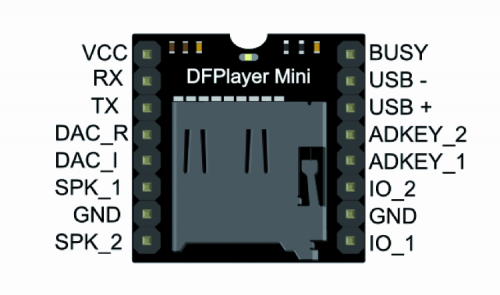
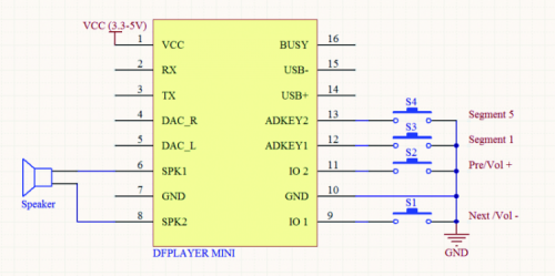
The nativity scene’s audio is obtained thanks to the effective module signed as DFR0299 (you will find it at www.futurashop.it/mini-riproduttore-mp3-montato-9145-dfr0299); it may be controlled by means of the serial interface; in our circuit it uses the microcontroller’s serial hardware interface, the same that is used in order to load the sketch on the microcontroller; this does not represent a problem, however, since the ATmega’s RX and TX lines are used for one function at a time: that is to say, once the microcontroller has been programmed, the sketch uses them in order to manage the module. In the diagram, you may find the DFR0299 represented with the U3 sign; it is capable of directly reproducing the MP3 and WAV files memorized on a SD-Card (having a maximum capacity of 32 GB, as long as it is a FAT16 or FAT32 formatted one) inserted into the dedicated slot.


Miniplayer_pin_map


The peculiarity of this module is that it has been designed and created for the Arduino world: even here the advantage of having an Arduino architecture on our board is obviously an advantage; as for the module’s management, clearly a specific library has been developed (it may be downloaded from our website, www.elettronicain.it, along with the other project files) and it has been included in our sketch; it allows to decide which file to reproduce, how to set the volume, and so on.


800px-Speaker2


The module contains a MP3 decoder and a controller, capable of accessing the data contained in the SD-Card, via SPI: as the data stream is gradually read, the decoder converts it in audio format, that is then amplified by a small integrated amplifier, a mono one having a 3-watt bridge output (that is more than enough power to drive a loudspeaker capable of making its voice heard in the environment). If more power is required, please use the audio output (SPK + and –) in order to drive a power amplifier, to which to apply a cabinet.

All of the functions of the U3 module are managed via serial interface, by means of specific instructions given by the microcontroller: those concerning the volume are generated by reading the ATmega’s ADC, when it samples the voltage on the R6 trimmer’s pointer. We also considered the usage, among the reproduction management commands (Play, Stop, Pause, FWD ecc.) only of the Play/Stop one, that has been implemented by means of the three buttons connected to the microcontroller, via the PD2, PD4 and PD7 lines (all of them are initialized as inputs supplied with an internal pull-up); all of them have the same function, that is to say, the one of enabling/disabling the audio. More precisely, the pressure of one among the P1, P2, P3 buttons (when a track is being played) determines the stop of the same, and a following pressure makes the track previously stopped to start from the beginning.

When the audio track is being played, the LD7 LED is turned on by the microcontroller’s PB5 line (that during the normal operation is used as an output); the PD0 and PD1 lines, depending on the UART, are coupled to the U3 module by means of resistors, so to avoid that – during the programming (that is to say, when the USB/Serial converter is applied to the board) – interferences might arise between the voltages of the two modules.

The files found on the SD Card must compulsorily have the name in the following format: 001.mp3, 002.mp3, 003.mp3 and 004.mp3. The first file is recalled during the day phase, the second one during the sunset, the third one when the hearths are turned on, regards the flickering lights) and the 004.mp3 file is recalled when the dawn comes. For this reason, you will have to rename the track you wish to be played during the day phase  as 001.mp3, the one for the sunset  as 002.mp3, the one for the hearths being turned on as 003.mp3, and the one to be recalled when the dawn comes as 004.mp3.

During the passage between a phase and the other, the playback volume will be gradually decreased until the end of the track, while the playback of the following track is started, with a volume gradually increasing (as it happens with the radio or the LPs); this happens for the transition from a phase’s track to the following one, and also for a track being reproduced in loop, it being understood that at the fade-out of a playback a similar one is started.


presepino 2


Well, having said that, we will complete the circuit’s description with the parts we omitted until now, that is to say the power supply, the ATmega 328P’s oscillator and the in-circuit programming: the circuit has to be powered with 12÷14 Vcc (the power required depends on how many users you are going to connect to the outputs…) via the +/- PWR terminal box, whose voltage directly reaches the MOSFET outputs and the connector for NeoPixel devices. The main power supply voltage reaches even the D1 diode’s anode (that has been included in order to protect the rest of the circuit from the reversed polarity risk), and is applied to the U2 voltage regulator’s input, whose task is the one to obtain the 5 stabilized volts used for the operation of the microcontroller, of the side components and of the U3 audio module. The possible USB/Serial converter will be powered by the USB voltage of the computer to which it will be connected.

The capacitors placed on the input power supply are needed in order to filter the pulses that are created on the tracks – as a result of the absorption of the LEDs, when they are turned on, and in general of the loads connected to the MOSFET outputs; this is needed since the pulse of the diodes’ power supply has a high frequency and otherwise the noises (that in the end are voltage drops – even if light ones – that are simultaneous with the single LEDs being turned on) might interfere with the microcontroller’s proper operation. The function of the C3 and C4 capacitors is a similar one.

Let’s get down to the interface for the in-circuit programming, now: it is to be used only if you want to load the bootloader in a “virgin” microcontroller; with regard to that, it must be said that the microcontroller supplied by Futura Elettronica (www.futurashop.it) along with the kit has already been programmed with bootloader and sketch. On the other hand, those who will prefer to get their own ATmega 328P elsewhere, will have as a first thing to load the bootloader, in order to be able to transfer the sketch from Arduino IDE.

The designated connector is the one signed as ICSP: the reset (RST), MISO (the programmer’s data input and U1 microcontroller’s output), MOSI (the programmer’s data output and microcontroller’s data input), SCK (the clock for the serial communication on the SPI, composed of the MISO and the MOSI) lines depend on it, in addition to the ground and the Vcc, that during the programming is supplied by the programmer, so to power the circuit. Let’s remember, in fact, that even when programming the bootloader, the circuit must not be powered by means of the +/- PWR terminal box.

Let’s end with the microcontroller’s oscillator, that is set as internal in the bootloader, and has a clock obtained from quartz X1, in parallel to which we will find the R19 resistor; the C5 and C6 capacitors complete the oscillator, that operates at 16 MHz: a frequency that is more than enough to manage the whole control box’s working cycle.


AlbaTramonto


Practical realisation

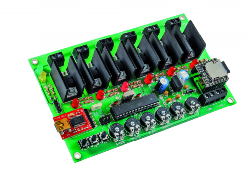
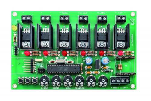
Let’s move now onto the subject of the board’s construction, that requires the preparation (or the purchase, since all the materials are available at Futura Elettronica) of a double-sided printed circuit board, whose tracks can be downloaded from our website, along with the other project files. Once the stripboard has been engraved and pierced, and the leads have been created (that is to say, the interconnections between pads that are common to the two sides) it is possible to mount the components, starting with the ones having the lowest profile (resistors and D1 Diode), and going on with the microcontroller’s socket, the 6-poles pin-strip with 90° terminals for the (optional) USB/Serial converter, the trimmers, the PCB buttons and the LEDs (to be orientated as shown on the assembling plane, and taking into account that the cathode is the electrode that has been placed on the container’s smoothed side). Please insert and weld the two female 8-pole pin-strips now, so to mount the audio module, the pin-strip for the ICSP (4 poles), the eight terminal boxes and the 7805 regulator, that must be kept upright, with the side having the writings pointed towards the microcontroller’s socket. Now the six MOSFETs must be mounted: each one of them has to be inserted in the corresponding hole in the printed circuit board, after having bent the terminals with a right angle and having put it on (with the side having the writings facing upwards) a “U” heat dissipator of the ML26 kind (thermal resistance: 22° C/W).

Once the weldings have been completed and you have verified that each component has been correctly mounted, and in the expected direction, please insert the DFR0299 module in its pin-strips (by orientating it so that the SD-carrier is pointed towards the outside of the circuit) and the microcontroller, whose reference notch must be pointed towards the integrated U2 regulator.

A micro SD card having the desired capacity must be inserted in the DFR0299, with the chosen audio files already loaded (please do it on a computer); what we claimed a few paragraphs above is valid for them as well. Please remember that – for obvious reasons – the duration of each one of them must not exceed the one that has been set for the phase it has to go with, thus, as an example, the theme being played for the day phase must not last more than the duration set for the day. It is not a problem if the file lasts less, since – it being the case – the file is cyclically reproduced until the end of the time set for the corresponding phase, and therefore faded out in time.

Please remember that the tracks must preferably be placed in the micro sd’s root, but anyway the module is capable of looking into the folders, it being understood that the reproduction order provided for our board would no longer be guaranteed.


presepino 3


At this stage, the control box may require the programming or not, depending on how you created it: if you have acquired a “virgin” microcontroller you will have (by means of the ATMEL programmer or of an Arduino board that has been set as a programmer: that’s the stand-alone programming technique) to load the bootloader by using, for the purpose, the ICSP connection. Once this has been carried out, by removing the programmer and by mounting the USB/Serial interface module in the U4 connector (it is the FT782M, a module that is available at Futura Elettronica, www.futurashop.it, and that is based on FTDI’s integrated circuit, FT232RL), the latter’s USB socket has to be connected to the one of the PC on which the Arduino IDE has been installed, and then the sketch has to be loaded (the IDE sees our board as if it was an Arduino UNO, since the bootloader loaded into the ATmega 328P is the same).

All of this is not required if you purchased the assembly kit, in which the microcontroller has been provided with all the basic functions programmed (4 outputs managed by 4 trimmers).

Anyway, in order to make our project easily adaptable to the user’s needs, the sketch is given in an open source format, and you will be able to download it, always from our website, along with the project files.

Therefore, even if you purchased the kit and are not satisfied with the basic configuration, and want to try to make some changes, you will have to acquire and mount the USB/Serial converter.


VIDEO


From openstore

Board control lights for the crib

FTDI USB-serial converter- 3,3V e 5V

DFPlayer – A Mini MP3 Player

FTDI Cable 5V

MINI LOUDSPEAKER – 2W / 8 ohm – Ø 66mm


Microsoft tastes the raspberry

$
0
0

fetarured


Let’s experiment with the embedded version of Microsoft operating system, by installing it on Raspberry Pi, and by building our first applications.


In our previous installment we could see some of the movements that are putting Microsoft in contact with the open source world, and we anticipated the release, by Microsoft, of a new Windows 10 version, specifically thought for Raspberry Pi: it is only the private “core” of the graphical interface the Microsoft users are used to. In this article we will see what it is about and the possibilities it offers. Before throwing ourselves headlong in the field of the technical features, we will list the requirements needed to test the operating system:

  • Windows 10 Insider Preview installed on a PC;
  • Raspberry Pi 2 and corresponding power supply;
  • 8 GB micro SD;
  • HDMI cable;
  • Ethernet cable;
  • a monitor to which to connect the Raspberry Pi board.


The official installation procedure requires the usage of a machine having Windows 10 installed; in truth there are some non official methods (found on the Internet) in order to install Windows 10 on Raspberry Pi, even if having previous Windows versions, OS X or Linux. In this occasion, however, we will limit ourselves to the official method.


Environment preparation

Let’s start, therefore, by preparing our Raspberry Pi for the installation: the first operation to execute regards the download of the tools and of the operating system, that must be carried out. An ISO will be downloaded from it, that is named “IOT Core Rpi”; by double clicking on the file the image will be mounted and a virtual drive will be assigned to it: there we will find the installation file. The following step concerns the execution of the “Windows_ 10_IoT_Core_Rpi2” installation file, that will install the tools and will put the veritable image in “C:\Program Files (x86)\Microsoft IoT\FFU\RaspberryPi2”.


Immagine1sistemata


The file we are interested in is named “flash.ffu” and represents the operating system image.

The FFU format has been specifically created by Microsoft for the deployment of Windows.
In order to create the SD card needed to boot the Raspberry Pi, it is needed to execute “WindowsIoTImageHelper”, that will present an interface with which to specify the SD card on which to write, and the FFU file path.


Immagine2sistemata


Once the two options have been indicated, it will be enough to select the “Flash” button and wait for the procedure to end.


First boot of Windows 10 IoT Core

Once the transfer procedure for the image has been completed, we will have our SD ready to be inserted in the Raspberry Pi, in order to start Windows 10. The first booting requires some time and the selection of some settings (language and possible parameters for the Wi-Fi, if available). After booting we will find ourselves before a screen like the one in figure.


Immagine3sistemata


If someone expected the familiar start menu or the “tiles” à la Windows 8, he will be disappointed: Windows 10 IoT Core is, in fact, a “down to the bone” Windows 10 version and, among the things that have been eliminated, there is the whole user interface. The purpose of this version is not the one to install application packages such as Office, but rather to have all the power of the Windows engine available, in order to develop Universal Apps. The screen we see, in fact, is none other than the default Universal App, executed at the start; in time we will be able to substitute it with our own.

It must not be forgotten that this version of Microsoft operating system has been specifically thought for developers. Not for no reason the banner down in the main screen shows “Visit windowsondevices.com to start developing”.

What we have to do now is to follow the indication we just received: we have in fact to temporarily move ourselves on our PC, having a “full” version of Windows 10 installed on it, and to download the development environment with which to create our first experiment.

Microsoft’s official development environment is Visual Studio: it is a very powerful and complete IDE. Luckily, Microsoft made Visual Studio available in the Community edition, which is free and can be perfectly used for our purposes. Let’s download it  and proceed with the installation.

If we correctly followed the previous steps, we should have the following tools at our disposal:

  • Raspberry Pi with Windows 10 IoT Core installed, better if connected to a monitor, mouse and keyboard;
  • a PC with Windows 10, having Visual Studio Community Edition and the Microsoft IoT components installed.


Ready to experiment

Once the stage concerning the environment preparation has been completed, we are ready to experiment; it is important to notice that, in order to follow the examples, it is needed that both Raspberry Pi and the PC having Windows 10 are connected to the same network. If this condition is met, we should see Raspberry PI listed in the Windows IoT Core Watcher tool. This tool was automatically installed when we initially installed the content of the “IOT Core Rpi”, and deals with the monitoring of the network, in order to search for devices having Windows 10 IoT Core installed; the fact that we see the board appearing in this tool is a confirmation that everything is ready and correctly configured.


Immagine4sistemata


Let’s start Visual Studio, then, and create our first project: in order to “warm up” we will start with a variation of the classic “Hello World”. We need to make a premise: when we will develop Apps for Windows 10 IoT Core, we will have two possibilities: to create headed or headless Apps. As it can be hinted by the name, the first ones are the ones that interact with the user by means of a user interface: in brief, they need at least the monitor and probably mouse and keyboard.

On the other hand, headless applications are more similar to what we are used to do, for example, with Arduino: that is to say, applications that do not benefit from a standard user interface but that directly interact with the hardware and the sensors. For now we will dwell upon the headed Apps that enable the interaction with the user, by means of a user interface.

Let’s create a new project, once Visual Studio has been started: we have to choose between “Windows Universal” and the creation of a project starting from the “Blank App” model.


Immagine5sistemata


Visual studio will create our project that, even if starting from the “Blank App” template, will turn out to be composed by a certain number of files. Among the generated files we will find MainPage.xaml, the XAML files being the files used to describe the user interface. In our case the file is composed only by the basic skeleton, but de facto it doesn’t have any content. As a first test we simply want the “Hello World” writing to appear in the center of the screen; let’s modify MainPage.xaml then, as shown in Listing 1.


Listing 1

<Page
x:Class=”App2.MainPage”
xmlns=”http://schemas.microsoft.com/winfx/2006/xaml/presentation”
xmlns:x=”http://schemas.microsoft.com/winfx/2006/xaml”
xmlns:local=”using:App2”
xmlns:d=”http://schemas.microsoft.com/expression/blend/2008”
xmlns:mc=”http://schemas.openxmlformats.org/markup-compatibility/2006”
mc:Ignorable=”d”>
<Grid Background=”{ThemeResource ApplicationPageBackgroundThemeBrush}”>
<TextBlock Foreground=”Blue” HorizontalAlignment=”Center”
VerticalAlignment=“Center” FontSize=“64”>Hello World</TextBlock>
</Grid>
</Page>


With respect to the original file, we added a TextBlock, that is to say a control capable of displaying a text. Its colour has been set to blue (with Foreground=“Blue”) and aligned to the center of the page (with HorizontalAlignment=“Center” and VerticalAlignment=“Center”).

Our first Universal App is ready: we may test it out. In the Visual Studio toolbar are the commands to control the App’s execution; as a first test we will execute it on our computer, for the purpose it is enough to click on the run button, that is to say, the small arrow that is similar to a “play” button.


IMMAGINE6sistemata


If we didn’t make mistakes, we will see a white page with a nice “Hello World” blue writing, in the center: it is a good result, but our objective was the one to create an App for Raspberry Pi. It is a very short step to get there. Always from the menu we used before, we find a drop down menu that indicates for which architecture to compile our App. As is known, Raspberry Pi is based on ARM technology, thus let’s select this architecture from the menu. Close to the button that we used to execute the App there is a label that claims “Local Computer” and here as well is the small icon, used in order to open a drop down menu.


Immagine7sistemata


Since we want to execute our code on Raspberry Pi, we have to select “Remote Computer”: a dialogue box will appear, to be used in order to set the board’s IP and the authentication (let’s select none for now). We are be ready again to press the execution button, but this time the App will be directly executed on Raspberry, and we will see the blue “Hello World” label to appear in the center of the monitor connected to the board.

Even if what we developed is something that is very simple from a functional point of view, we reached a very important stage. To be able to execute the App both on the local computer and on the remote device is something very important in the prototyping phase, and it enables a much greater speed, for example, in the interface design stages. Obviously, as we add the functions for the interaction with the board’s hardware to the App, it will be our duty to conditionally manage the presence or the absence of the required devices.

Let’s go on, therefore, by expanding the starting example a bit, in order to interact with the hardware; after all one of the main purposes of what we are examining is just to supply a simple and powerful tool to the Makers.

What we want to do now is to try to turn on a LED, via a click on a button displayed on the monitor’s screen. For this example we should connect a LED to one of Raspberry Pi’s GPIOs: we will use pin 18.


Immagine8sistemata


Given that we haven’t yet interacted with the board’s hardware, we didn’t consider the package needed to do that until now. To do that, as a first thing, let’s click with the right mouse button on “References” (while in Visual Studio’s “View Solution Explorer”) and let’s make the context menu appear. From it we will select “Add Reference”, once a dialogue box appears with a list of entries on the right. Let’s select “Windows Universal” and type in “IoT” in the search text box that is up and on the right; in this way the list should show us a single element: “Windows IoT Extension SDK”. Let’s select it and click on OK, in order to install it.


IMMAGINE9sistemata


The “Windows IoT Extension SDK” package offers us all the specific extensions needed in order to work with the hardware; of them we will use the classes that enable the interaction with the board’s GPIOs.

Let’s start, therefore, to modify the code, in order to adapt it to the new needs: as a first thing we will modify the XAML file in order to create the interface we want; the content of MainPage.xaml will be as shown in Listing 2.

Listing2

<Page
x:Class=”App2.MainPage”
xmlns=”http://schemas.microsoft.com/winfx/2006/xaml/presentation”
xmlns:x=”http://schemas.microsoft.com/winfx/2006/xaml”
xmlns:local=”using:App2”
xmlns:d=”http://schemas.microsoft.com/expression/blend/2008”
xmlns:mc=”http://schemas.openxmlformats.org/markup-compatibility/2006”
mc:Ignorable=”d”>
<Grid Background=”{ThemeResource ApplicationPageBackgroundThemeBrush}” >
<StackPanel HorizontalAlignment=”Center” VerticalAlignment=”Center”>
<TextBlock Foreground=”Blue” HorizontalAlignment=”Center”
FontSize=”48”>LED Control</TextBlock>
<Button Click=”Button_Click” HorizontalAlignment=”Center” Margin=”
0,50,0,0” FontSize=”64” >OFF</Button>
</StackPanel>
</Grid>
</Page>


We have added a StackPanel, that is a content control needed when we want to have more elements at our disposal in the interface. In particular, the StackPanel enables the disposition of the elements in a column, one after the other (it is possible to work with a horizontal orientation, if needed).

Inside the StackPanel there is the same TextBlock found in the first example, that simply serves as a title for the page. Under the TextBlock we will insert a Button, whose purpose is the one to create a button in the interface. The button is an active control, in the sense that it is capable of unchaining an action before an event. The Click=“Button_Click” attribute indicates that when the button will be pressed, the code of a method named Button_Click will be executed.

Let’s see then the code that is executed when clicking on a button, as shown in Listing 3.

Listing3

bool state = false;
const int LED_PIN = 18;
GpioPin pin;
private void Button_Click(object sender, RoutedEventArgs e)
{
state = !state;
var pinValue = state ? GpioPinValue.High : GpioPinValue.Low;
pin.Write(pinValue);
Button btn = (Button)sender;
btn.Content = state ? “ON” : “OFF”;
}


The button acts as a switch that turns the LED on and off, depending on the “state” variable. At the same time the button label is modified, and set to “ON” or “OFF”, in order to indicate the LED’s state; as it can be seen from the code used to modify the button’s label, the “Content” property is a valued one here.

The interaction with the GPIO is carried out by means of the “pin” item, obviously this item must be defined somewhere, and configured with the specification of the pin on which to work, and if in input or in output. All of this happens in a method named at the App’s boot, as shown by Listing 4.

Listing4

private void InitGPIO()
{
var gpio = GpioController.GetDefault();
pin = gpio.OpenPin(LED_PIN);
pin.SetDriveMode(GpioPinDriveMode.Output);
pin.Write(GpioPinValue.Low);
}


InitGPIO does exactly what has just been described, as a first thing it obtains an instance of the GpioController, that as you can imagine represents the GPIOs’ management class.

Once the controller’s instance has been acquired, it is used in order to create the “pin” item, and the pin on which it will have to act is specified (in our case LED_PIN, that is to say the number 18). By configuring the operating mode in Output, and by setting the pin at a low level, the initialization is complete. Obviously, InitGPIO will have to be recalled at the App’s boot.

The complete example of the LED control program can be downloaded.


IMMAGINE10sistemata


Configuration Panel

We have experimented with the board and discovered that it is very simple to create Apps. By progressing towards more complex applications, however, one will have to confront with the need to control the system’s function parameters. Windows 10 IoT Core offers a management web interface as the default one, these are the parameters that can be reached at the following web address: http://minwinpc.local:8080.

The address is given by the default name that is assigned to the board; obviously it is possible to modify it and in that case the url changes as well, alternatively it is possible to use the IP address in the place of minwinpc.local.

The default access credentials are “Administrator” with “p@ssw0rd” as a password (and obviously it would be better to change it if using the board outside of your laboratory).

The interface is a very simple one, but it is no less efficient because of it: it allows to see the list of the processes being executed, to analyze the CPU load and the RAM consumption in real time, to execute or stop the Apps, and has many other interesting functions.


IMMAGINE11sistemata


An interesting function is the one that enables the deployment of applications without having to go through Visual Studio: this is a great help when the board is not connected to the development environment.


Conclusions

In spite of such a superficial view of Windows 10 IoT Core, we could perceive some potentialities that we would define as exciting. The first thing to point out is that when talking about Universal Apps, we are talking about applications that can be virtually executed on all the devices that are supported by Windows 10. The simple examples that we showed in the article can be executed, for example, on a Windows Phone, obviously with the appropriate controls for the usage of specific hardware such as GPIOs. By considering only the field of the embedded boards, we will find that there is not just Raspberry Pi, but for example we will find Intel Galileo, and in this case our App can be executed on different platforms, with minimal modifications that in certain cases may even be unnecessary.

Another distinctive factor is the development efficiency, given by the usage of a professional tool such as Visual Studio, and by the work cycle that enables development, debugging and deployment in a totally integrated way. We didn’t consider the possibilities offered by the interaction with Microsoft’s Cloud, Azure, that enables to move the applications from a hobby level to the professional level, but keeping the same simplicity at work.

In conclusion, we feel sure that Windows IoT Core will soon carve out an important space for itself, in the already crowded world of tools used by the Maker’s community. We can’t but appreciate the efforts that Microsoft is putting in order to offer a legacy of competences and technologies that otherwise it would be impossible to reach.


From openstore
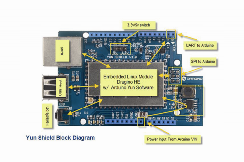
Starter kit for Raspberry PI 2 model B

Raspberry Pi 2 Model B


Top Projects for a Merry Christmas

$
0
0

Over the years we presented several projects to celebrate Christmas.
it is time to present those who have had the greatest success.


1°: Spherebot Reloaded: Customize Your Xmas

spherebot_fea

Let’s create a plotter to decorate Christmas Tree balls with writing and drawings.

Christmas is coming you dusted off your xmas tree and decorated it: everybody try to make it different, buying new decorations and balls of different colors. Well, if you are looking for something original, think of making your personalized balls with drawings and writings at will.

Here comes this machine: a printer, or better to say a plotter, which will draw with a marker on spheres at will, derived from models transformed into G-code files. The machine is easily doable with a few 3D printable pieces (we’ll provide the relative models in a special Thingiverse page) and a control board which is the same of the 3Drag. A computer will be needed for the appropriate printing software.

Read the full article

2°: Arduino DMX shield for Christmas projects

bell

This shield allows to connect an Arduino with DMX equipment. It implements the RS485 interface to adapt the electrical levels needed for DMX connection.

This shield has been designed with flexibility in mind and allows the user to choose between several Arduino pins for digital input and output of DMX data, it supports a microSD slot and also has the serial connection to support a serial LCD display.

This design allows basic operation of DMX through simple pre programmed messages stored in the Arduino Sketch or, with the proper libraries and programming, it could well become a standalone system with playback capabilities of sequences stored on the microSD. When needed, this solution is also a suitable interface for a PC sending through a serial port the DMX commands.

Read the full article


3°: Presepino: the nativity scene with Arduino

presepino featured

A light system, capable of simulating the alternation of night and day, that will make your nativity scene – be it a small or a big one – even more realistic. Our circuit is capable of piloting four light loads, corresponding to the daylight, to the brilliance of the stars, to the household hearths, and to the guiding star. It allows the control of LEDs and of a NeoPixel strip.

Read the full article


4°: Light up your XMAS from your Smartphone

xmas1079Fea


Every year at Christmas we always want to try something new for lighting up our decorations: everyone wants to impression friends and families coming to visit with her creativity! So, this year we propose you an interesting idea: a system that manages the lighting according to your favorite song.

Read the full article


5°: DIY LED Plexiglass christmas decorations

bell


Very few components, plexiglass and a CNC are the ingredients to make wonderful brilliant figures to decorate the Christmas tree or our house this Christmas and New Year. Let’s see how to do it.

Read the full article (Arduino version)
Read the full article (PIC microchip version)


6°: An intelligent XMAS Lamp to Light up your Christmas!

Xmas_fea


The Christmas eve is approaching and – even if we’re a bit late on this – we make a Christmas Lamp, capable of emitting light of the same color of the surface it is laid on!

Read the full article


And more and more….


Mery christmas from Open-Electronics


Creating a geolocalized relay, thanks to Microsoft Virtual Shield for Arduino

$
0
0

featured


Let’s experiment with the Virtual Shield tool for Arduino, found in the last Microsoft operating system, for the purpose of creating a smartphone based geo-fence application, that would activate a relay when the phone is found inside a certain area.

In the two previous installments we introduced you to the projects connected with Microsoft’s entrance into the Makers’ world, and in particular we dwelled upon Windows’ distribution for Raspberry Pi: it is named Windows 10 IoT Core and created for the purpose of simplifying the applications’ development cycle. We will see now what has been done for Arduino instead, and in particular we will see the usage of Windows Virtual Shield, by creating a simple project in order to show its potentialities. What we want to create, even in its simplicity, can be used in real contexts: it is a relay that is activated when being near a determined spot. Already in the previous article we quoted this kind of usage for Virtual Shield, as a solution for the opening remote control (to be used to open the garage’s gate in the place of the classic remote control). In the project here described, it will be Arduino (installed in the car) to send the command on our behalf when we are nearby, by using a smartphone supplied with a GPS receiver (this last one will supply the data concerning the position).


Needed materials

The project requires the following devices:

  • Arduino Uno or a compatible board;
  • a Bluetooth FT1018M module having RN42 (that we presented in number 168 of the magazine);
  • a smartphone having a Windows Phone 10 preview (for example, Lumia 520, Lumia 635/630 are okay);
  • a PC having Windows 10 installed.


Given that this is an educational project concerning Windows Virtual Shield, we will use a breadboard on which we will build the relay circuit, commanded by Arduino. The external components with which we will interface Arduino are simply a relay, and as much is needed in order to obtain its activation (in practice, a transistor and a resistor).

Environment preparation

The environment preparation is quite articulated and can be divided in three main steps:

  1. configuration of the development environment on the PC;
  2. smartphone configuration;
  3. Arduino IDE configuration.


Let’s start by preparing the development environment on the Windows 10-based PC: for this purpose we should download and install Visual Studio 2015. Once the development environment has been installed, we will use it in order to install the “Virtual Shield for Arduino” Universal App on the mobile phone. This App (supplied in the source form) will deal with the management of the communication with Arduino, by exposing the sensors and the components used by the phone. The App sources are available on GitHub; for those who know GitHub already, it is possible to make a clone of the repository (Visual Studio directly supports GitHub from the environment). For those who are not familiar with GitHub, the easiest approach is the one to download the zip with the sources and to double click on Shield.sln, so to open them with Visual Studio.

Once the sources have been loaded with Visual Studio, it is the time to try to execute “Build”; if no errors have been detected, you will have completed the PC configuration.

Let’s move onto the mobile phone, then: in this case the operation is a bit easier. The ideal would be that of possessing a smartphone we don’t use as our main phone, since at the moment this article is published the Windows 10 version for smartphones is still in a preview phase and Microsoft does not guarantee on its reliability: to install it means to accept the risk that the mobile phone might operate poorly.

In order to install Windows 10 preview, it is enough to download “Windows Insider” from the App Store. Once executed, the application goes on in a semiautomatic way, the only requirement being the one to be registered to the Insider Preview program, but even this registration is a free one and can be done by following the indications from the App. Before starting the Windows 10 preview installation process, the App will ask us to choose between “Fast” or “Slow” updates: in the first case the system will receive updates more often, but they will potentially be less stable ones; in the second case, there will be less updates, but they will be more stable ones. For our test, both conditions will be fine, thus we will let you choose as you prefer.


Immagine1


Once the installation is complete, we are ready to connect the phone to the computer and, to install “Virtual Shield for Arduino” by using Visual Studio; if the previous steps have been carried out without problems, the operation simply consists in clicking on the small arrow akin to “play”, close to the “Device” writing: it can be found in the upper bar.


Immagine2


An important notice: it may happen that Visual Studio will send an error warning, since the version for which the project has been configured is one that follows the operating system found on the phone; unfortunately this is a known problem and one has to act manually in order to solve it. In the case you find yourself in this condition, as a first thing you will have to take notice of the version detected on the phone by Visual Studio, that will be shown at the same time of the error warning. After that, please open the Shield.csproj file via notepad: it is inside the sources folder, and please insert the read version in the TargetPlatformMinVersion tag; as an example, if we read 10.0.10149.0 we will have to set the tag like this: <TargetPlatformMinVersion>10.0.10149.0</TargetPlatformMinVersion>. This is needed in order to indicate that the minimal version that is supported by the project is the specified one and, since it corresponds to the phone’s one, the problem will not occur again.

All that is left to do now is to configure the Arduino part: as a first thing we have to download one of IDE’s new versions (from 1.6 and up). Once the IDE has been installed, we have to download ArduinoJson library; luckily in the new versions the LibraryManager has been included.  


Immagine3


It may be accessed from the menu Sketch->Include Libraries->Manage Libraries…: with this command a pop-up is opened, from which to choose the library to install; by filtering ArduinoJson the library we are looking for will be shown and it will be enough to give the Install command to install it.


Immagine4


The final step is the one to download and install the libraries for the virtual shield, and unfortunately, since they have not yet been included in the Library Manager, we have to proceed with the manual installation. Luckily, the operation is not an excessively complex one: you just have to download the repository  and to copy the whole content in the folder in which the IDE keeps all the libraries (typically Documents\Arduino\libraries).


The ever-present Hello World

Once we have reached this stage, we should have our environment ready for the first test that, as tradition dictates, will be the classic Hello World. “Almost” is the key word here, since we haven’t fiddled with the hardware yet. Actually in this first stage, the one of the diagram’s application, it is enough to connect the Bluetooth module to the Arduino board.


Immagine5


The first test is a very simple one and consists in creating a sketch that will use the phone’s display in order to write “Hello World”.

The code to load is the one in Listing 1.

Listing1

#include <ArduinoJson.h>
#include <VirtualShield.h>
#include <Text.h>
VirtualShield shield;
Text screen = Text(shield);
void refresh(ShieldEvent* shieldEvent)
{
screen.clear();
screen.printAt(1, “Hello World”);
}
void setup()
{
shield.setOnRefresh(refresh);
shield.begin();
}
void loop()
{
shield.checkSensors();
}


Briefly, the item of the VirtualShield kind is created (in the example it is named shield), it represents the communication interface with the phone. The item is used along with the Text class, that shows the functions needed to interact with the phone’s display. One of the example’s peculiarities is that the calls needed to display the text are not made directly in the loop function, but they are in the refresh function; in turn this is transferred as a parameter to the setOnRefresh method. Such a mechanism delegates to the shield item the function’s call when it is needed (for example, when starting the program or after the bluetooth connection). In order to see the sample work, it is needed to couple the Bluetooth module to the phone: the procedure is the classic one followed in order to couple Bluetooth devices. From the settings, please select “Devices” and then “Bluetooth” and from this screen the Bluetooth is activated (if turned off), waiting for some seconds while the other devices in the operating range are activated. The device’s name to be coupled will be something like RN42-1234 (with 1234 being different for each module); by selecting it the coupling will be carried out.

Let’s start now the “Virtual Shield for Arduino” app on the phone, at the start of it a black screen will be shown in figure.


Immagine6


This is the proper behaviour, since the black area is the one made available to Arduino, in order to show text or graphical contents; down and on the right the usual key having three dots “…” is found, it indicates that there is a drop-down menu. Let’s select it and a menu having some buttons will be shown, among them the one we’re interested in is “Settings”.

The “Connections” section is the one we are looking for, in which all the the Bluetooth devices coupled with our mobile phone will be shown; among them there will be our module. Let’s select it, and by pressing “Connect” we will end our preparation phase. At this stage, by returning to the main screen (with the back key) we should see “Hello World” appearing, as sent from our sketch loaded on Arduino.


The project

But let’s see now how to activate a relay when we are getting close to a certain area.

The circuit to be created is the one in Fig. 5, there we will find a transistor being used in switching mode, for the purpose of commanding a relay. The remote control’s transmitter button is connected to the two terminal block’s contacts, that depend on the exchange normally opened by the relay (C-NA). When the relay is excited, the contact will turn out to be closed and will activate the transmission on behalf of the remote control, that will send the opening command for the automatic gate.

The logical steps describing the circuit’s operations are:

  1. the recurring reading of the GPS position;
  2. the calculation of the distance, with respect to a determined spot (the gate to be opened);
  3. relay activation, if the distance is under a prearranged threshold.


As for the position reading, we will use a class of the Virtual Shield that has been specifically designed for this purpose; as for Text, it is initialized by transferring the shield item, which it will use in order to communicate with the phone:

Geolocator gps = Geolocator(shield);

The GPS variable represents the item we are using in order to read the position; the periodic reading will happen by means of the previously seen callback mechanism. In our sketch’s setup we will have the call set the function needed in order to read the position: it will be periodically called; in our case we will make a reading every 15 seconds. Please note that it is important to balance this time, so to avoid too frequent readings that would hinder the autonomy, since we are talking about a battery powered device. At the same time, if our readings are too sparse, we will determine delays in the relay’s activation, with respect to the input in the objective’s proximity area. As a measure of caution, we should get closer only after having seen the gate opening.

The code line that sets the callback is gps.setOnEvent(gpsEvent).

Let’s see then the gpsEvent function, that is the one we required to be called when there are updates in the position reading: it is related in Listing 2.

Listing2

void gpsEvent(ShieldEvent* shieldEvent)
{
float distance = calc_dist(gps.Latitude, gps.Longitude, myLatitude, myLongitude);
String diststr = String(“Distanza “) + String(distance) + String(“ mt”);
screen.printAt(3, diststr);
if (distance < threshold){
screen.printAt(5, “Rele’ ON”, GREEN);
digitalWrite(PIN_RELE, HIGH);
}else{
screen.printAt(5, “Rele’ OFF”, RED);
digitalWrite(PIN_RELE, HIGH);
}
}


The coordinates related to the position are made available in gps.Latitude and gps.Longitude; previously we will have set two more coordinates (corresponding to the spot with respect to which to calculate the distance; in the source they are myLatitude and myLongitude) in the source. The function then calculates the difference between the read coordinates and the reference ones; because of this we will call another function, calc_dist, that uses a mathematical formula in order to carry out the relevant calculations (the function is reported in the complete source that you will find in Listing 4). Once the distance has been obtained, we will create a string (diststr) that we will use in order to show what has been read on the mobile phone’s display. The veritable heart of the function is the test that checks if the distance variable is under the prearranged threshold (indicated by threshold) and, in case, it activates the relay connected to the pin defined by PIN_RELE. The example is deliberately a simplified one: when we enter the relevant area (that we may consider as a “geo-fence”), the relay remains excited until we remain inside of it; obviously it is possible to introduce to introduce something to manage this condition, but we preferred to keep the code readable. locking the callback is not enough though: if we do not set a periodic call that triggers the position reading. As is natural in an Arduino program, this activity is carried out in the loop: we can see it in Listing 3, that relates the corresponding code section.

Listing3

const long interval = 1000 * 15; //15 secondi
long nextGPS = 0;
void loop()
{
if (millis() > nextGPS) {
nextGPS = millis() + interval;
gps.get();
}
shield.checkSensors();
}

Listing4

#include <ArduinoJson.h>
#include <VirtualShield.h>
#include <Text.h>
#include <Colors.h>
#include <Geolocator.h>
VirtualShield shield;
Text screen = Text(shield);
Geolocator gps = Geolocator(shield);
// Coordinate del punto rispetto al quale misurare la distanza
float myLatitude = 45.092949;
float myLongitude = 7.523704;
// Soglia entro la quale attivare il Relè
float threshold = 50;
// Pin al quale è collegato il Relè
int PIN_RELE = 7;
void gpsEvent(ShieldEvent* shieldEvent)
{
float distance = calc_dist(gps.Latitude, gps.Longitude, myLatitude, myLongitude);
String diststr = String(“Distanza “) + String(distance) + String(“ mt”);
screen.printAt(3, diststr);
if (distance < threshold){
screen.printAt(5, “Rele’ ON”, GREEN);
digitalWrite(PIN_RELE, HIGH);
}else{
screen.printAt(5, “Rele’ OFF”, RED);
digitalWrite(PIN_RELE, HIGH);
}
}
void setup()
{
shield.begin();
screen.clear(ARGB(0,0,0));
screen.printAt(1, “Rele’ Geolocalizzato”);
gps.setOnEvent(gpsEvent);
pinMode(PIN_RELE, OUTPUT);
}
const long interval = 1000 * 15; //15 secondi
long nextGPS = 0;
void loop()
{
if (millis() > nextGPS) {
nextGPS = millis() + interval;
gps.get();
}
shield.checkSensors();
}
// Calcolo della distanza tra due coordinate (in metri)
float calc_dist(float flat1, float flon1, float flat2, float flon2)
{
float dist_calc=0;
float dist_calc2=0;
float diflat=0;
float diflon=0;
diflat=radians(flat2-flat1);
flat1=radians(flat1);
flat2=radians(flat2);
diflon=radians((flon2)-(flon1));
dist_calc = (sin(diflat/2.0)*sin(diflat/2.0));
dist_calc2= cos(flat1);
dist_calc2*=cos(flat2);
dist_calc2*=sin(diflon/2.0);
dist_calc +=dist_calc2;
dist_calc=(2*atan2(sqrt(dist_calc),sqrt(1.0-dist_calc)));
dist_calc*=6371000.0;
return dist_calc;
}


The request to read the position’s coordinates is carried out via the gps.get() call, in order to manage the reading frequency we use the millis() function, so to carry out the call only when at least 15 seconds from the previous request have passed.


Conclusions

Those among you who are experienced with Arduino might be wondering about the difference between using Virtual Shield and a GPS shield that is physically mounted on the board.

From an operational point of view we will have the same results, but the usage of Windows Virtual Shield brings a series of advantages.

First of all, the hardware interface for Arduino is much simpler: in our case it comes down to connecting a Bluetooth module and a relay. Moreover, our project uses the smartphone’s display in order to show some messages; if we wanted to create the project in a “classic” way, we would have had to worry about interfacing a display and maybe to acquire a case, in order to place it (also considering that the typical use case for our project is the one of a remote control for the gate opening, to be placed in a car, as we already anticipated in the introduction).  Because of this usage, we need that Arduino is capable of accessing the geolocation data, only when we are in the car as well. To use an integrated GPS module would make sense in the case of an anti-theft alarm, but in this case we may avoid buying the component.

Finally, the fact of using a virtual shield (that has a very large series of sensors available) gives us the possibility to extend our project in the future, without having to act on the circuit. For example, we could make it produce a sound or synthesize a vocal message when we get close to the gate: for such a purpose, just a few more code lines in the sketch would be needed.


From openstore

Breakout RN-42 Bluetooth module

Arduino UNO R3


The 3Drag Big: stretching 3Drag’s printing capabilities

$
0
0

featured


When the standard model is not enough, you can “stretch” the printer to print objects up to 400x200x200 millimeters. Here’s how to make the change.


To print great objects, you need a great printer -and our 3Drag is great- but if you want to print three-dimensional objects that are oversize, then you need a large printer. So we decided to work on a new 3Drag update, which differs from those already proposed (CNC milling machine, chocolate printer) because it is not only a change of printing head but rather a “lateral stretching” of the case to become big enough to allow printing up to 400x200x200 mm instead of the standard 200x200x200 mm objects size. In this way the 3Drag, from now on dubbed 3Drag Big, can print shoes prototypes, hulls for ship models, architectural scale models, aircraft parts like tails, wings or fuselage, and so on.

Without much fussing, we will explain how to turn your 3Drag into a 3Drag Big: to upgrade the standard model you have to replace the two side profiles of the base frame with longer ones (850 mm), the X-axis two Ø10 mm ground steel rods with two longer (797 mm), the X-axis belt with a 1.5 m long (available as spare part on openstore cod. BELT6T5 / 1500 / SP) and the original printing plate with a wider one, by 405×205 mm.

To complete the upgrade, you must also provide this material:

  • one M5 square nut;
  • a M5x12 screw;
  • two M3x16 TC screws;
  • 10 countersunk head M3x8 screws;
  • one M5 toothed washer;
  • 14xM3toothed washers;
  • 12xM3 nuts;
  • plastic ties 100 mm and 200 mm long


The aluminum square section profile used for the frame can be purchased from our store (cod. PROFALL275– available in 1 meter bars) while the Ø10 mm ground steel rods, the 2 mm thick aluminum plate and the two 405 mm long, 15x15x1,5 mm aluminum angle brackets (used to “enlarge” the printing plate), can be found in hardware stores or well supplied DIY centers.

Of course we must make again the motors and X&Z-axis limit switches wiring, having changed the corresponding elements position; for this purpose, we suggest to purchase the flat cable sold by Openstore cod. FC16C-3/SP, using only the needed wires.

Before proceeding with the modifications, you need to print with the 3Drag the X-axis limit switch mounting bracket (shown in figure) whose “.stl files” can be downloaded here.


fig1


The first thing to do is cutting all the ties clipping the wiring coming from the control board and going to the X axis motor/limit switch, toward the X tray and to the Z axis motor/limit switch.

Then, remove the printing plate from the X tray (if you have installed the heated plate, its power supply and control cables must be disconnected and isolated by means of heat shrink pieces to prevent short circuits). Note that the heated plate is not available for the 3Drag Big, so you need to disable it; using Cura Engine as a slicer, just click Setup / Filament and set the value “5 ° C” for the “Plate temperature” and replace the NTC with a 22KOhm 1/4W resistance (otherwise the program will wait until the temperature set has been reached and will not start printing). If you prefer Slic3r, just set 0.0 temperature to turn off the plate.

After that, let’s remove the X-axis motion system (toothed belt, motor with bracket, the pulley and its bracket that is fixed on the frame left side near the Z axis), as shown in figure.


fig2


Now you can remove from the base frame the two 45 cm long aluminum profiles (front and rear) indicated by red arrows in figure  (to do it, loosen the related angle brackets screws).
Keep apart these two profiles, since you’ll need them to complete the 3Drag Big frame.


fig3


Now remove all the screws that lock the two X-axis Ø 10 mm ground rods to the frame; the screws are those shown in figure.


fig4


Done this, pull out the X-tray from the frame by sliding the related bars toward the printer front.


fig5


You can then extract the X-tray ground bars, then unscrew the four angle brackets at the base of the two struts and remove the two aluminum profiles put at the base frame side (the 416 mm long ones).

Mount the new 850 mm long profiles replacing those we have just removed; these are obtained by cutting properly the two 1 meter bars purchased from our store.

Temporarily position the new struts at the center of the two bars without tightening the related angle brackets screws (the correct position will be checked ​​later).

Assemble on the 850 mm bar the 450 mm rear section (we disassembled it at the beginning of this guide) after inserting on the latter (the printer center facing end) five square nuts (used for X rods supports and pulley).

Fix temporarily to the bar by means of the nuts just entered the two X axis ground bars supports and, between these two (approximately in the center position), the X-axis pulley and its bracket.

Then tighten the angular profile screws (those assembling the 450 mm and the 850 mm sections together), and fix to the 850mm sections the four studs exactly as they were mounted on the original chassis.

Take the tray and place it at the center of the printer keeping its connection flat-cable facing the control board.

Now take the two 10 mm diameter and 797 mm long ground round bars and insert them first on the X-tray sleeves, then in the related supports previously fixed to the rear base profile (the 450 mm one); the situation will be that visible in figure.


fig6


Place a M5 square nut in the 850 mm right profile appropriate cage (the profile is the one close to the control board, the cage is that facing the tray): this nut will be later used to secure the X-axis limit switch support. Now take the other 450 mm profile and do the same as before but this time you need to fix, between the two ground bar supports, the X-axis motor with the pulley facing left, as seen in figure; the pulley must be located approximately at the center of the bar and the bracket screws, for the moment, just hand tightened.


fig7


Mount together the 450mm section to the two 850mm side sections and lock them in place by tightening their angle brackets screws, then position the bars so that they are parallel and equidistant from the base side profiles. Slide the tray from one end to another to make sure it moves freely and tighten gradually and alternately all the screws on the support bar. If the tray movement is not smooth, repeat the alignment. Attach to the base, with a 200 mm tie, the tray flat cable. The result should be the one visible in figure.


fig8


Now it’s time to mount the X-axis motor so that its pulley is about 195 mm far from the controller hosting aluminum section. Place the other X-axis pulley so that its respective bracket is far about 200 mm from the same section bar.

Done so, you have to pin one end of the belt to the X-tray by using a clamp screw. Now stretch the belt and let it pass over the two X-axis pulleys, then insert the free end on the other clamp screw on the X-tray. Tighten loose the clamp screws just to avoid belt slipping and verify that the tray can move end-to-end smoothly. If it is ok, the two pulleys are aligned, otherwise correct the positioning of each element. Finally, secure all the related components permanently to the frame.


fig9


Aligned everything, loosen the latter clamp screw and stretch the belt to the right tension, then tighten the screws for the final fixing. Check again that the tray is free to slide on its guides from end to end.

The last operation on printer mechanics consists on positioning the two struts spaced 46 cm from the base front profile. When this is done, it must be double checked that the extruder nozzle is able to reach the two ends of the plate. If necessary, you have to correct the struts positions otherwise you can proceed tightening the angle bracket screws.


Wiring

Once the mechanics has been completed, we must focus on rewiring the electrical and electronic parts; about this, which shows the electrical connection between the X/Z motors and their related limit switches to the 3Drag control board, done by using a 160cm 12-way flat cable suitably sectioned. One end of the flat cable must be connected to the printer control board using the board-to-wire cables recovered from the original 3Drag wiring, respecting the color association of each conductor as shown in the diagram.

Lay the printer on the Z-axis side, then distend under the base frame the flat cable leaving it near to the motor and to the Z axis limit switch (securing it with cable ties in the most suitable points) separating properly the conductors shown in the diagram in correspondence of the elements to be connected (motors, limit switches).

As a first step you have to connect the flat cable to the Z axis switch and just after its engine, following strictly the scheme, so as not to burn the motor driver.

Then connect the X-axis motor; Also in this case we recommend to fully observe the diagram in figure, to avoid damaging the driver.

Made connections, fix where necessary the flat cable to the frame, using the plastic ties.


fig10


Printer plate

Now we focus on making the new printer plate (the X-axis limit switch will be addressed later): Take the 2 mm thick 205×405 mm aluminum plate and drill it as shown in figure.

All the holes done should be countersunk on one side (the plate “printing side”); the four central holes will host the same 4 M4x20 screws used on the original printing plate, while the ten holes drilled on the two longer sides will host 10xM3x8 countersunk head, fixing the angle brackets. Now take two 15x15x1,5 mm, 405 mm long aluminum brackets and draw on their side the center line. Then drill five Ø3mm holes spaced 96mm each other and starting from 10.5 mm from one end (these holes will be matching those done on the plate longer sides).

The angle bracket drilling guide with all the distances is reported in the figure.


fig11


Screw tight all the M4x20 as in the original 3Drag plate. Insert the M3x8 screws, mount the angle brackets, insert on each screw a M3 toothed washer and a nut which you will use to fix the aluminum angle brackets. Now you can apply to the four central screws the gear knobs (which will serve to align the plate horizontally) 


fig12a fig12b


Now you can mount the plate on the printer tray. Note that to ensure the best printed object adhesion to the plate we suggest to apply the blue paper tape available at our store (cod. BLUTAPE3M) or two pcs of BuidTak, as shown in following figure. Now you can take care of the X axis limit switch, which must be removed from the X motor and mounted instead on the right side section profile (same side of the control board) using the bracket previously printed with 3Drag.


fig13


The support should be put about 14 cm from the front of the frame and secured with a M5x12 screw with toothed washer and the M5 nut previously inserted on the right side (the screw, for the moment, should be kept close). Now fix the microswitch to its support (by means of two M3x16 TC screws, each with four toothed washers and one M3 nut), after having positioned so that the metal tab touches the X-tray plastic support placed behind the Y motor.

Fix now the electrical connections, taking care to leave enough free cable (50 mm are more than enough) in order to have the possibility, during the calibration phase, to move a few centimeters the limit switch.


fig14


Move the plate toward the X motor so that the nozzle is aligned with the end of the plate itself and then fix the limit switch so that it is triggered at this very point. Finally tighten with an Allen wrench the M5 screw; this adjustment is not critical but determines the X-axis “HOME” position. Now you can finish the job by fixing with a 100mm plastic cable tie the wiring.


fig15a fig15b


Using the 3Drag Big

To fully utilize the printing area you need to change the printer settings (in Repetier-Host click on Configuration/Printer settings/printing plate options) by entering the new plate size (the X axis).

The printing time of larger items can be reduced by replacing the standard 0.5 mm nozzle with a 0.8 mm (available from our store cod. NOZZLE08)

3Drag BIG allows the mounting of a printing plate having maximum dimensions of 550×205 mm, like the one visible in figure, obtained from a 2 mm thick aluminum “sheet” folded at 90 ° on the longer sides.


fig16


It is imperative to keep in mind that the larger plate dimensions allow the printing of bigger objects but also that this increases the whole printing system oscillations, reducing thus the definition and quality of the final output.


From openstore

3Drag – 3D printer – KIT

Expansion set for printer 3Drag

3D printer 0.8 mm Nozzle

Flat cable multicolor

Aluminium profile 27,5mm x 27,5mm – 1m


Blue tape for 3d printer

Toothed rubber belt – 1.5 meters

Fishino: let’s look inside the features

$
0
0

featured imm

In this second “episode” (here the first one), we will go deeply inside Fishino features, showing the main libraries and code sketches.


In the last post we have presented the Fishino UNO board, compatible with Arduino UNO but offering WiFi connectivity, a microSD slot and a built-in RTC.

In this second post we begin describing the available software libraries, explaining the main functions with some simple examples of use.

As anticipated, both the board firmware and the software libraries are constantly under development, so we recommend keeping them constantly upgraded.


Libraries

To take advantage of all the Fishino features we must obviously have a set of software libraries to handle all the additional components.

If the SD card and the Real Time Clock (RTC) functions are already available in the corresponding Arduino libraries, the ESP12WiFi module is not present in the suite, that’s why we had to develop a proprietary library.

We will start then from the Wi-Fi features, but later we’ll provide details on those already available in the IDE too.

The supplied libraries, freely downloadable from our site are:

  • ‘Fishino’
  • ‘FishinoWebServer’
  • ‘Flash’


The last library, Flash, is freely available on internet but we have inserted it in the downloadable package anyway, since it is a necessary component for the functioning of the previous two.


figu3 


‘Fishino’ Library

Let’s start with the description of the library (which can be downloaded from fishino website) that handles the Fishino WiFi module lower and middle level.

This defines three classes:

  • FishinoClassand its global variable “Fishino”
  • FishinoClient
  • FishinoServer


The project is constantly evolving, well supported by a very active community on Facebook; 

Thanks to this community, we will add in a second phase the FishinoUdp, FishinoAnalog, FishinoDigital and FishinoSerial libraries to manage respectively the UDP network protocol, the analog inputs, the digital I/O and the additional hardware serial port built on the WiFi module.

Let’s begin with the FishinoClass description (single instance in the global variable Fishino), explaining with practical examples the various functions.

With bool Fishino.reset () we can initialize the WiFi module by sending a software reset. Required at the very beginning of your sketch to ensure a successful module boot. Returns TRUE if the module has been properly initialized, FALSE otherwise.

The reset function also checks the firmware version. If outdated, sends an error message over the serial port and the program is stopped. Listing 1 shows an example of proper initialization routine in the Setup function. Apart from the usual serial port initialization (to be done at the beginning of setup), you see:

  • initializing the SPI
  • Fishino.reset ()to init the module

Listing1

void setup()
{
Serial.begin(115200);
while (!Serial);

SPI.begin();
SPI.setClockDivider(SPI_CLOCK_DIV2);
if(Fishino.reset())
Serial.println(“Fishino WiFi RESET OK”);
else
{
Serial.println(“Fishino RESET FAILED”);
while(true)
;
}
Serial.println(“Fishino WiFi web server”);
<span style="font-weight: 400;"> </span>

The first procedure has been intentionally left “manual”, not included in a function, to have more flexibility in order to change the communication speed, if there are other shields using the same interface. In this example, we set it to the maximum available speed.

The section containing the Fishino.reset () call, initializes the module and sends a message over the serial interface if successful. Otherwise, in case of problems, reports the error and blocks the sketch.

Warning, the WiFi module DON’T start without this command.

bool Fishino.setMode (uint8_t mode) and uint8_t Fishino.getMode (void) functions set (or read) the module working modes (Listing 2), that can be as follows:

  • STATION_MODE It requires a Wi-Fi router to connect to. It is the normal working mode.
  • SOFTAP_MODE creates an access point you can connect to. Useful in the absence of an existing network infrastructure.
  • STATIONAP_MODE Dual mode, the module works either as an access point or connecting to an existing router.

Listing2

Fishino.setMode(STATION_MODE);

To connect to the access point / router you must use the bool Fishino.begin (SSID, PASSWORD) function. Obviously, SSID is the network name and PASSWORD, if not needed, can be left blank.

To check whether Fishino is properly connected, the command is uin8_t Fishino.status (). The function returns TRUE if the connection is successful, FALSE otherwise. In the code snippet in Listing 3,  the connection function is invoked in an endless loop until it is successful.

Listing3

while(true)
{
if(Fishino.begin(“MY_SSID”,“MY_PASSWORD”)) {
Serial.println(“Connected to MIO_SSID”);
break;
}
else {
Serial.println(“Failed connecting to MIO_SSID”);
Serial.println(“Retrying.....”);
}
}


This type of connection procedure (executed in the Setup function) is suitable for a fixed application since it is a high resource consuming, of course. If using Fishino in mobility, you can move the connection function in the loop () and invoke it on a schedule while doing other activities.

This way you can, for example, collect data from a sensor, store them on the SD card and when a working connection is detected, send them to a remote computer (Listing 4). In this example (intentionally abbreviated), in setup () it is read the current time and stored in the connectTime variable; later in the loop () we check the elapsed time (millis () – connectTime) and every 10 seconds run a connection test. If not connected you try to connect to the server and, if successful run a function (to be defined) that saves on the network the previously read data.

Listing4

uint32_t connecTime;
void setup()
{
..............
connectTime = millis();
}
void loop()
{
if(millis() - connectTime > 10000) {
connectTime = millis();
uint8_t stat = Fishino.status();
if(stat != STATION_GOT_IP) {
if(Fishino.begin(“MIO_SSID”, “MIA_PASSWORD”))
stat = STATION_GOT_IP;
}
if(stat == STATION_GOT_IP) {
salvaDatiSulServer(); 
}
leggiSensoriEMemorizza(); 
}


The loop then continues through another function (also to be defined) that reads from a sensor and stores the data locally, i.e. on the SD card.

With this sketch is thus possible to make a simple data logger which not only reads and stores data on the SD card, but which, in the presence of a network connection, is able to save them in a completely automatic manner at predefined time intervals.

To configure a static IP and DNS servers, Gateway, and the subnet on the local network use these functions:

bool Fishino.config (IPAddress local_ip)

bool Fishino.config (IPAddress local_ip, IPAddress DNS_SERVER)

bool Fishino.config (IPAddress local_ip, IPAddress DNS_SERVER, IPAddress gateway)

bool Fishino.config (IPAddress local_ip, IPAddress DNS_SERVER, IPAddress gateway, IPAddress subnet)

In practice, the first sets a static IP, if necessary. In Listing 5 we see how you can set a static IP (192.168.1.251). If you don’t use this function, the IP address will be automatically set by the DHCP.

Listing5

Fishino.config(IPAddress(192, 168, 1, 251));


We could also disconnect the network. The command to do this is bool  Fishino.disconnect (void).

Here are also some functions used to control the connection parameters:

  • To read the WiFi module MAC: const uint8_t* Fishino.macAddress (void)
  • To get the IP acquired by the WiFi module (useful if you set a dynamic IP) invoke IPAddress Fishino.localIP () as shown for example in Listing 6.
  • To get the subnet mask and gateway IP address, you can call these functions:
    • IPAddress Fishino.subnetMask ()
    • IPAddress Fishino.gatewayIP ()

Listing6

Serial.print(“My IP: “);
Serial.println(Fishino.localIP());


The functions listed above were named in a similar way to the corresponding ones on Arduino Ethernet and WiFi library, in order to simplify the porting of existing code.

However the higher Fishino potential, and especially the possibility to operate also in access point mode without needing an existing infrastructure, requires us to study the new functions introduced by the station mode, including:

bool Fishino.setStaIP (IPAddress ip)

bool Fishino.setStaMAC (uint8_t const * mac)

bool Fishino.setStaGateway (IPAddress gw)

bool Fishino.setStaNetMask (IPAddress nm)

While the access point mode uses:                            

bool Fishino.setApIP (IPAddress ip)

bool Fishino.setApMAC (uint8_t const * mac)

bool Fishino.setApGateway (IPAddress gw)

bool Fishino.setApNetMask (IPAddress nm)

bool Fishino.setApIPInfo (IPAddress ip, IPAddress gateway, IPAddress netmask)

In particular, the last is used to set all Fishino IP parameters when configured as a WiFi router, with a single command (Listing 7).

Listing7

Fishino.setApIPInfo(
IPAddress(192, 168, 100, 1), // IP 
IPAddress(192, 168, 100, 1), // Gateway 
IPAddress(255, 255, 255, 0) // Netmask 
);

We will see how to use them at the end of this article with a complete example. In order to read WiFi connection data and settings, such as the network SSID you are connected to, the router MAC (BSSID), the signal strength in dBm (RSSI) and the network security, you can use these functions :

const char * Fishino.SSID ()

const  uint8_t* Fishino.BSSID ()

int32_t Fishino.RSSI ()

uint8_t Fishino.encryptionType ()

As shown for example in Listing 8.

Listing8

Serial.print(“Connected to: “);
Serial.println(Fishino.SSID());


There are also some functions used to list available WiFi networks with their characteristics:

uint8_t Fishino.scanNetworks ()

This will scan for available WiFi networks and returns the number of found networks.

After the scanNetworks, you can use the following functions, passing the network number as a parameter (total number is given by scanNetworks () – 1).

The function const char * Fishino.SSID (uint8_t networkItem) returns the SSID, i.e. the network name as shown in Listing 9. This example prints on the serial interface a list of the wireless networks found.

Listing9

uint8_t n = Fishino.scanNetworks();
if(n) {
Serial.print(“Find “);
Serial.print(n);
Serial.println(“ wifi:”);
for(int i = 0; i < n; i++) {
Serial.print(“Network #”);
Serial.print(i);
Serial.print(“ : “);
Serial.println(Fishino.SSID(i));
}
}
else
Serial.println(“No WiFi found”);


To know the type of network security, the right command is uint8_t Fishino.encryptionType (uint8_t networkItem).

We can also know the network signal strength with int32_t Fishino.RSSI (uint8_t networkItem).


FishinoClient and FishinoServer

These two classes are the Arduino Ethernet and Wi-Fi shields EthernetClient / WiFiClient and EthernetServer / WiFiServer equivalents, and their use is virtually identical.

For example, to send a request to a web page and print the response on serial interface check Listing 10.

Listing10

FishinoClient client;
if (client.connect(“www.google.com”, 80)) {
Serial.println(“connected to server”);
// esegue un request Http
client.println(“GET /search?q=arduino HTTP/1.1”);
client.println(“Host: www.google.com”);
client.println(“Connection: close”);
client.println();
do {
while (client.available()) {
char c = client.read();
Serial.write(c);
}
}
while(client.connected());
Serial.println(“Client disconnected”);
}
}


At the end of this post, we present a complete example that shows one of the most attractive features of Fishino, i.e. the possibility to create a network infrastructure without an external router, connecting to it for example with a mobile phone.

A similar application could be used, for example, to remotely monitor a number of outdoor sensors via a mobile phone, making so ​​fully portable devices.

Another interesting application could be a WiFi remote control always via the phone web browser.

The example in Listing 11 creates a WiFi network named (SSID) ‘FISHINO’ without a password (open network) and starts a small server that provides on demand a reading of the six analog inputs present on Fishino. Once launched the sketch, you must select your wireless network (FISHINO) between available networks and connecting to 192.168.100.1 on the browser you get the result shown in figures.


Fig_1

Fig_2


The examples presented here are included, along with others, in the Fishino library.

Listing11

#include <Flash.h>
#include <FishinoUdp.h>
#include <FishinoSockBuf.h>
#include <Fishino.h>
#include <SPI.h>
#define My_SSID “FISHINO”
#define My_PASS “”
FishinoServer server(80);
void setup()
{
Serial.begin(115200);
while (!Serial);
SPI.begin();
SPI.setClockDivider(SPI_CLOCK_DIV2);
if(Fishino.reset())
Serial << F(“Fishino WiFi RESET OK\r\n”);
else
{
Serial << F(“Fishino RESET FAILED\r\n”);
while(true);
}
Serial << F(“Fishino WiFi AP web server\r\n”);
Fishino.setMode(SOFTAP_MODE);
Fishino.softApStopDHCPServer();
Fishino.setApIPInfo(
IPAddress(192, 168, 100, 1), // IP
IPAddress(192, 168, 100, 1), // gateway
IPAddress(255, 255, 255, 0) // netmask
);
Fishino.softApConfig(My_SSID, My_PASS, 1, false);
Fishino.softApStartDHCPServer();
server.begin();
}
void loop()
{
FishinoClient client = server.available();
if (client)
{
Serial.println(“new client”);
boolean currentLineIsBlank = true;
while (client.connected())
{
if (client.available())
{
char c = client.read();
Serial.write(c);
if (c == ‘\n’ && currentLineIsBlank)
{
client.println(“HTTP/1.1 200 OK”);
client.println(“Content-Type: text/html”);
client.println(“Connection: close”); 
client.println(“Refresh: 5”); 
client.println();
client.println(“<!DOCTYPE HTML>”);
client.println(“<html>”);
for (int analogChannel = 0; analogChannel < 6; analogChannel++)
{
int sensorReading = analogRead(analogChannel);
client.print(“analog input “);
client.print(analogChannel);
client.print(“ is “);
client.print(sensorReading);
client.println(“<br />”);
}
client.println(“</html>”);
break;
}
if (c == ‘\n’)
{
currentLineIsBlank = true;
}
else if (c != ‘\r’)
{
currentLineIsBlank = false;
}
}
}
delay(1);
client.stop();
Serial.println(“client disonnected”);
}
}


One last note on I / O already used by devices: those can’t be shared with other applications when these devices are used. The WiFi module uses the following pins: 7, 10, 11, 12 and 13. It is completely deactivated with a jumper between CH_PH ESP and ground pins. 

The microSD card uses the following pins: 4, 11, 12 and 13 and requires the pin 7 set to digital output. To release those resources, simply do not put a memory card into the connector. 

The RTC module communicates by using i2c pins SCL and SDA, coupled on Arduino UNO to analog ports A4 and A5.


From open store

Fishinouno

Exploring the Open Source Ethernet Broadcaster

$
0
0

featuredmp3


In this second and final post we will go deep inside the Ethernet audio streaming transceiver firmware.

 Recently, we have presented an Ethernet audio streaming unit. In particular, we have shown how to configure the boards to work with other similar devices or with VLC Media Player, setting up a point-to-point or a broadcast streaming in all possible configurations. Also in the first episode, we analyzed the electrical circuit and the components choice. Now it is time to describe the board software advanced options and how to update firmware via Internet or manually.


AUTHENTICATION AND LOCAL NETWORK

In the Authentication page, you can change your credentials to access all the restricted areas. The software allows two roles, each accessible with username and password. The software recognizes as Admin the role with the highest level of administrator privileges, only it can change all available settings; instead the role with less rights is simply “User”. When you login as administrator in the Authentication page, you get a form (first figure), where you can change your credentials; similarly, when you login as user (as in second figure) you can change the user role settings only.


Figura 1

Figura 2


Each time a user changes values on an editable field, the “Save” and “Save and Apply” buttons are activated, allowing the saving of changed information. The difference between the two commands is that while the first (Save) saves the changes without ending the current session (so you can modify other parameters), the second button (Save and Apply) saves data and close the session, asking your login data again if you want continue making additional changes.

The last Authentication page command is “Do logout”, which terminates a previously authenticated session; the same effect is obtained by closing the browser.

From the Local Network page, however, you can configure the network settings: in particular, you can view or change the MAC address and the network basic input / output system of the network device. The latter, known as NetBIOS is a session layer protocol developed by IBM and Sytec, whose ease of use has made ​​it a widely used standard especially in MS Windows environment. It is not a protocol of fundamental importance, but in local networks where IP addresses are often dynamically assigned by the DHCP server, it helps identifying the device: it is enough to perform searches by name rather than by IP (dynamic).


Figura 3


The network devices identification process is very similar to the name service implemented by the DNS and the idea behind is the same, i.e. providing some mechanism to contact a network device from its associated unique name. On Windows, the service is often enabled by default, while on Unix systems it is necessary to enable it manually.

We conclude the description of available commands in the Local Network page with “Enable DHCP“ checkbox, that enables the Dynamic Host Configuration Protocol (DHCP): when the checkbox is unchecked, the page allows manual editing of IP Address, Gateway, Subnet Mask and DNS servers.

When you opt to use DHCP (the checkbox is checked), network parameters are not editable and the fields are used to display the current configuration obtained by DHCP.


USB CONFIG

The USB Config page lets you interact with the USB pen-drive: in particular, you can explore the mass storage device connected to the transmitter and then checking its stored files; a representation is visible in figure.


Figura 4


You can also change the default file name given to recordings done from the network stream, with the Recording filename setting. The same form lets you choose actions to be taken if the filename already exists. The possible actions are two and are “overwrite the existing file” or “add a unique time stamp”.

The time stamp will be formatted in the following way: hhmmss_GGMMYYYY where hh stands for hour, mm stands for minutes, ss stands for seconds, DD for day, MM for month and YYYY per year.

The actions associated to “Save”, “Apply” and “Save and Apply” buttons are respectively save to permanent memory and activate only at the next reboot, apply changes immediately and do not save them in memory and, ultimately, save and apply changes immediately.


Senza nome


DYNAMIC DNS

Dynamic DNS (DDNS abbreviated) is a technology derived from the Domain Name System (DNS), which allows you to associate an IP address to network or domain names. The main difference between the two services is that while the DNS is administered worldwide through a distributed database and the insertion of a new DB record is regulated by a hierarchical authorization mechanisms that makes it “static”, the DDNS implements more or less the same functionality but for devices that are subject to frequent IP change (like domestic ADSL without a public IP).

This feature allows you to bypass the problem of having a dynamic IP using just one of the many DDNS services available on Internet (some of them free).

To ensure that there is always the right matching, the device running the DDNS client must contact the remote server and update the database entry with the new IP address value assigned each time.

In order to make the board always remotely available, even if the Internet service provider is constantly changing the assigned IP address, you can click on the Dynamic DNS menu item and enter the requested parameters for one of the three DDNS services available provides an example in which the broadcaster.noip.me host name is associated to the board under test.


Figura 5


In the “public IP” field, as shown also in the figure, there is the public IP used to access the Internet. If the board is connected to a home LAN, you should configure router’s port forwarding, i.e. you must tell the DNAT service that when external LAN requests match a particular pre-assigned port number, those incoming connections must be correctly routed to our board and not dropped!


DATE & TIME

The board ​​implements a hardware clock and a calendar: clicking on Date & Time menu item you can access this information and configure the clock. The first two fields (current time and current date) show the time & date values from the RTC. Moreover, as seen in figure, you can select the time zone, (Italy is GMT + 1) and enable DST (Daylight Saving Time).


Figura 6


Finally, you can choose to manually enter the correct time or keeping it automatic by using the Network Time Protocol (NTP); in the latter case, since the board is not equipped with a buffer battery, the NTP is particularly effective to set the exact time at each restart. Ticking the Enable Network Time Protocol checkbox, will allow you to select the NTP server or manually enter time and date.


ADVANCED FEATURES

In the Advanced menu, there are some advanced features, such as reading the statistics, board reboot, reset factory data, firmware check and upgrade.

In the upper part of the page, as shown in figure, four statistics are shown. Up Time indicates the total operating time in days, hours and minutes since last statistic counters reset or the last software update, this value is updated every 10 minutes, fractions below this threshold are ignored to prevent flash memory degradation. Run Time indicates the total board operating time since last reboot, updated every minute: this value is stored on RAM only and can be updated more frequently. Restart times counts the number of board reboots and finally Reconnection times the number of reconnection attempts. The value refers to the automatic reconnect and is reset each time the board is turned off or you proceed with the manual connection. The checkbox send statistics enables statistics monitoring and sending data to the remote server.


Figura 7


The check new firmware item shows the current firmware and hardware version and allows, using the procedure described in the next section, to update the transmitter firmware. Finally, the last two items allow you to restart the board (in 3 seconds) and to reset it to factory settings. The factory reset can also be done by holding down for more than four seconds both left and right buttons during the power on phase. A very fast blue and central-red LED blinking indicates this state. When the blue LED start blinking regularly, the board is operational again.


FIRMWARE UPDATE

Trying to give this project a long life, we have chosen to design the software into two parts, a bootloader that is factory loaded with the appropriate In Circuit Serial Programming (ICSP) programmer and an app that contains the actual functionalities supported by our board.

The bootloader is loaded in a separate microcontroller memory area and will not change unless we intervene again with the programmer. The app is installed in a rewritable memory area by the boot loader, which allows you to make firmware updates without a dedicated tool.

In this section we describe how to update the firmware, every time we want to add new features or to correct any bug. In a normal use scenario, just go through the browser to the right configuration page by clicking on the Advanced menu item. This page shows firmware and current hardware version, as shown in figure.


Figura 7


Clicking on Check now button, it will check for a new firmware version. This procedure will contact the remote server and will check for updates available for the specific hardware. If it is available, a warning message will appear as shown in figure and the Update now button gets active. Before proceeding with the upgrade you must insert a USB pen-drive formatted to FAT16 or FAT32 with enough free space (at least 10 MB), then you can proceed with the procedure by clicking the Update now button.


Figura 8


The firmware update process may take some time and it is very important not to remove the USB pen-drive or unplug the power connector: you risk freezing the board, making it unusable.

To make sure that a corrupted firmware or any error during the process could damage the board, the microcontroller will calculate the received firmware MD5 comparing it with the hash communicated by the remote server. Only when there is a perfect matching between the two hashes, the software will proceed with the upgrade by copying the files block to the microcontroller flash memory.

If not matching, the PIC will interrupt the firmware upgrade process and return an error message. During the new firmware download (stored into the usb pen-drive) the microcontroller will continue working normally and the blue LED will flash regularly; When this phase is finished, the microcontroller will start calculating the MD5 hash and this stage is signaled by red LED steady on. After verification, if everything is fine, the red LED flashes slowly; from this moment, the real firmware update process begins and it is important that the power supply is not interrupted until done.


Figura 9


In this phase, the bootloader will erase the old app and install the new one. When the cancellation procedure is complete, the red LED will be off and the central red LED will flash rapidly. When the blue LED will start flashing again regularly, at 1HZ, the procedure has been executed perfectly and the board will be operational.

During the entire update, the management web interface will show the progresses done. The “upgrade successful” is shown by the message in figure , which will automatically be displayed when done.


Figura 10


If you have network problems or you can’t access to the management web page, you can upgrade the firmware manually.

In this case, we must first reset the board to factory data, by holding the left and right buttons (on the board) for more than four seconds, and then manually load the new firmware into the USB stick, renaming it exactly “image.hex”.

Now you must plug the usb drive to the board that is switched off after the factory reset. Set a jumper on board J5 connector, and wait for the update, which will last a few seconds and is usually indicated by red LEDs flashing.


Figura 11


After this stage you will need to update the management web pages, so you may need to access from the browser to the IP address assigned by DHCP; for example, the URL may be http://192.168.3.16/mpfsupload; or, if you are using a MS Windows pc with NetBIOS enabled, simply go to http: //MCHPBOARD/mpfsupload.

From the specific page, you have to select the “page.bin” for all the web pages you want to upgrade and then click Upload.


Figura 12


From openstore

Ethernet MP3/Ogg Vorbis Broadcaster


Fish’n Tweets

$
0
0

featured


With this project we’ll show a practical application of our Fishino board that allows a very simple and cheap way to control remote appliances as lamps, heaters, climatizers, alarms, etc.

The peculiarity of our system is that it doesn’t need any external support server nor special network interface boards, but just a Fishino UNO board and possibly one or more relay boards to drive connected loads. This application which can’t be done with a simple Arduino, even not if provided with a common WiFi or Ethernet shield, has been made possible by Fishino’s capability to handle secure connections with HTTPS protocol, which is usually available on more expensive boards; to stay into Arduino world, now at least a YUN board is needed to achieve same purpose, and with a more complex software.

There are many possibilities for the remote control of electric appliances, each with own Pro and Cons.


fig_b


Let’s see an incomplete list of them:

  • Control by SMS – Advantages:
    • Receiver can be portable and independent of network infrastructures
    • Fast – commands are executed almost instantly
    • Can be controlled from any cell phone, even from older ones
    • Practically unlimited rangeCaveats:
    • A SIM card is needed on controlled board, which usually has an expiration time
    • It needs a GSM board, not very cheap
    • It needs GSM network coverage, not everywhere available
  • Radio control – Advantages:
    • Receiver can be portable and independent of network infrastructures
    • Fast – commands are executed almost instantly
    • Very chealCaveats:
    • Very limited range
    • Range depends on obstacles between sender and receiver
  • Remote control over internet – Advantages:
    • Can be made portabled at the price of a GPRS board
    • Can be controlled by any PC or recent cell phone
    • Quite cheap if you’ve a network infrastructure in place
    • Can be made bidirectional with no costCaveats:
    • A network infrasctructure or a GPRS board is needed, which can be expensive
    • Stability depends on network conditions
    • Response times can be very variable
    • Often it needs complicated boards and/or support external PC
    • Usually a public IP or a way to bypass this limitation is needed,
    • Security problems are always possible

With this project we aimed to join the advantages of control by internet removing some of its caveats, using a well-known public service: Twitter.

In practice, the applicances are controlled by a simple Tweet in a given format, from a given user (or more users, with some small changes in software).

With this approach we solve the following caveats of internet control :

  • Connection stability. On network failures the command is stored by Twitter network and executed when network goes up again.
  • The receiver is quite simple, both on hardware and software side.
  • No public IP is needed, nor an intermediate support server
  • Security is granted by Twitter infrastructure, which operates over HTTPS protocol.

Al usual also this method has some caveats, which are the non-immediate actuation (tweet propagation times are variable from some seconds up to a couple of tenths of seconds) and some limitations (easily solvable) on duplicates tweets.

Let’s see first the usage, and then the application description.

Appliances are controlled sending a Tweet with following format :

#hashtag port ON/OFF

where ‘#hashtag‘ is a customizable hashtag that can be changed inside the software (in our case we adopted #fishino), ‘port‘ is a Fishino digital port number (more about it later) and ‘ON‘ or ‘OFF‘ are the commands to turn on or off the digital output.

Example:

#fishino 24 ON Turn output 24 on

#fishino 10 OFF Turn output 10 off

As above forementioned, there is a variable lapse of time from tweet message and command execution which is usually between 5 and 20 seconds, depending on Twitter network status.

The other caveat is the impossibility to send duplicated tweets in short time; for example:

#fishino 24 ON Turn output 24 on

#fishino 24 OFF Turn output 24 off

#fishino 24 ON Turn output 24 on

Third tweet is rejected by Twitter because is a duplicate of first one in too short time.
The problem is solvet quite simply by adding some random text character after ON word:

#fishino 24 ON 123456 Turn output 24 on

Additional random chars (123456) are simply discarded by receiver.


How it works

Let’s start from sended Tweets, which is stored and propagated into Twitter network. Anybody can see, receive and search for the tweet from everywhere.

Using a cell phone or a PC it’s possible to search it, for example, using the sender and the hashtag as query strings:


TwitterSearch


Search results are something like following picture:


TwitterResult


As you can see, matching Tweets are shown, from most recent one.

Let’a analyze more in detail the single tweet; every message has:

  • a sender (@OpenElectronics)
  • zero o more hashtags (#fishino)
  • a text message, including the hashtags and other text
  • a timestamp, showing send date and time
  • it can embed references to other people, images, urls, etc.

In our application the important fields are the sender, used to allow or deny the access, the hashtags, used to separate normal tweets from commands, the text, which contains the appliance command, and finally the timestamp, which is used to separate already executed commands from new ones.

We can’t of course execute such a search with a PC to control our appliances; we need something more “machine usable” way.

Twitter API (Application Programming Interfaces) comes in help allowing to execute, among others, search on twitter network in a simple way.

Twitter API

The API are quite large, and allows to do almost all operations on twitter network, as searches and sending of tweets.

In our controller we’re interested in a small subseto of the API, the search APIs.

API usage is quite uniform and, once the usage of a small subset is understood, the extension of the whole APIs is straightforward.

The biggest problem (and security advantage!), which usually makes it impossible to use the API from embedded controllers is the secure protocol used by API.

Tweeter uses, to strenghten the system security, these 2 ways :

  • connection to the API’s server MUST been done over HTTPS protocol
  • API’s user MUST authenticate himself with one of the methods that we’ll see on next paragraphs

The second requirement is easy enough to meet, but for the first a system able to make secure connections is needed.
This implies that APIs can’t be used with Arduino’s Ethernet/WiFi shields, for example, which operates only on unsecured protocols.

Fishino is able to execute an HTTPS connection to time.

Let’s see in detail a typical https request to Twitter API:

GET /1.1/search/tweets.json?count=1&q=%23fishino+from%3Amdelfede&result_type=recent&max_id=647068135569387520&since_id=646038066440896517 HTTP/1.1
Host: api.twitter.com
User-Agent: Fishino Twitter Client
Authorization: Bearer AAAAAAAAAAAAAAAAAAAAxxxxxx


First row is the true request :

  • GET /1.1/search/tweets.json?
    is the request on search APIs
  • count=1
    is maximum number of requested results; we want a tweet per request
  • q=%23fishino+from%3Amdelfede
    we search for fishino hashtag (%23, #) coming from user (%3A,@) mdelfede
  • result_type=recent
    we want results sorted by timestamp and not by popularity
  • max_id=647068135569387520
    IDs are timing sequence numbers embedded in each tweet. In this case we want a tweet not newer than the supplied id
  • since_id=646038066440896517
    We wants only tweets newers than supplied id
  • HTTP/1.1
    closes HTTP query

Second and third rows are the address hosting the APIs (api.twitter.com) and the application which is executing the query (Fishino Twitter Client); the latter can be almost any string and is uset just to identify the application using the API.

Next row is quite important; it’s used to authenticate the request on twitter network :

Authorization: Bearer AAAAAAAAAAAAAAAAAAAAxxxx

Twitter network, as forementioned, uses 2 methods to strenghten the security : HTTPS protocol (which avoids attacks like “man in the middle”) and some authentication keys.

Latter can be of 2 kinds : personal o di application-only.

With the formers the access is done as a twitter user, and act exactly as him; it’s possible, for example, send tweets as if they were sent by an human over a PC.

Secon kind of authentication is more limited, being tied to the application, so partially anonymous. You can’t send tweets with it, but you’re limited to some kinds of operations like tweet searchs.

In our application we used the latter method, because it’s less rate limited than the forst one and allows more requests per our and, more important, the requests are separated from user-authenticated ones.
The limits are actually of 180 requests every 15 minutes, both for usage as an user and as an application. So, if we execute 180 requests in 15 minutes as an application we still have the same amount of them available as an user.

Passing these limits means account suspensions, so it’s better to not exetuce too many requests in short time; 180 requests every15 minutes means an interval of 5 seconds between them.

How to get a ‘Bearer’ authorization key

Here we explain how to create a Twitter application and get it’s auth key.

We need of course to have a Twitter account and open following link :

https://apps.twitter.com/

You’ll get the following screen :

fig_2a

In this case we see an already registered application (FishinoBreakTheSafe) and the ‘Create New App‘ button. Pushing it you’ll get following screen :

fig_4

Now some input is needed :

  • Applicaztion name (Name); in this case FishinoTestApp

  • Application description (Description); in this case “Prova di applicazione Twitter per Fishino

  • Website : a website which should show application’s details; mandatory, but can be a simple placeholder. In this case www.fishino.it

  • Callback URL : not needed here (leave empty)

At page bottom you find the usual service agreement checkbox and the create button (Create your Twitter application) :

fig_3a

Pushing it you’ll get following page :

fig_3

Application has been created and the system shows (obscurated here) the ‘consumer API key’, which is one of the needed keys.

As we want to use the ‘Bearer token‘, the one needed in Application only mode, we need one more step; click on above tab ‘Keys and access tokens‘; you’ll get following screen :

fig_5

You’re told that the application has not still been autorized (below ‘Your Access Token‘). Pushing the ‘Create my access token‘ button below you get :

fig_6

Below the text ‘Your Access Token‘ you’ll see now the 2 keys needed for application usage in user-mode . Last step needed, to get the Application-only key, which is the one we’ll use in our application, it’s usually the more complicated, because on API documentations the way to get it is explained but no simple page is given to do it. So, we have made an http page at the following address

www.fishino.it/bearer.php

which allows to get the ‘bearer token‘ quite easily:

fig_7

It’s enough to enter the ‘consumer_key‘ and the ‘consumer_secret‘ from application’s page, and push the ‘Generate token‘ button to get the key ready to be copied and pasted in our sketch. A last note: the key is shown in 2 lines because of limited space, but it is a single line key.

The sketch

Let’s see the sketch, now, starting from configuration data on file’s beginning part, so the impatients can test it quickly :

//////////////////////////////////////////////////////////////////////////////////////////

// CONFIGURATION DATA -- ADAPT TO YOUR NETWORK !!!

//////////////////////////////////////////////////////////////////////////////////////////

// CONFIGURATION DATA -- ADAPT TO YOUR NETWORK !!!

// here pur SSID of your network

#define MY_SSID "CASA"

// here put PASSWORD of your network. Use "" if none

#define MY_PASS "unapassword"

// here put required IP address of your Fishino

// comment out this line if you want AUTO IP (dhcp)

// NOTE : if you use auto IP you must find it somehow !

 #define IPADDR 192, 168, 1, 251

// here put your application Bearer authorization key

// see https://dev.twitter.com/oauth/application-only for details

#define BEARER "AAAAAAAAAAAAAAAAAAAAA.........."

// here put your Twitter user name; if empty the application will react to ANY user

#define TWITTER_USER "pippo"

// here put twitter hashtag needed to trigger the event (without the # char!)

#define TWITTER_HASHTAG "fishino"

// here put the delay in milliseconds between requsts

// there is a limit of about 180 requests every 15 minutes, so don't put a too short time here

#define REQUESTS_INTERVAL 5000

Settings are quite simple; if you’ve already run some Fishino application you’ll notice that the oprions are almost the same for all of them; in detail, near the and of configuration block you’ll see the part needed for Twitter, ad the Bearer Token which we discussed on former paragraphs (BEARER), the twitter user name (TWITTER_USER) from which the command tweets must be made, the activation l’hashtag (TWITTER_HASHTAG), to insert WITHOUT the ‘# character and finally the time interval between 2 requests. About latter parameter, as we explained on former sections, Twitter has some limits on requests number that can be done in some time; passing these limits means the applocation block, sometimes temporarly, sometimes forever. Now the limit is of 180 requests every 15 minutes, so about a request each 5 seconds. We suggest to not use a value less than the suggested 5000 milliseconds if not for short tests.

Sketch description

We’ll skip the initialization part, almost identical for each Fishino application; if you’re interested on it we suggest to look at FishinoHomeAuto description. We limit the description to the 2 most interesting parts, the Twitter API’s usage and the optional IO expansion.

About the APIs, we notice the first difference from other applications :

// The web secure client used to access twitter API

FishinoSecureClient client;

We use the FishinoSecureClient instead of FishinoClient. This client is used to make HTTPS connections.

API’s connection is done by aid of following code chunk :

if (!client.connected() && !client.available())

{

Serial.println("\nStarting connection to server...");

if(client.connect("api.twitter.com", 443))

{

Serial.println("connected to server");

// run the query looking from given hashtag and user

doQuery(client, "%23" TWITTER_HASHTAG);

}

}

We check if client is still connected from preceding loop and/or if it has still data to be processed, as data is maintained inside a buffer even after the client get closed. If not, we open the connection to the site api.twitter.com on port 443 which is the one used for https connections.

If connections is successful we send the request by aid of the doQuery() function, whic has as parameters the client and the given hashtag.

This function just sends the data to Twitter API server :

// run a query on twitter

void doQuery(FishinoSecureClient &client, const char *query)

{

// if walkback is finished (nextID == -1) we reset sinceID to next found maximum ID

// otherwise we let it as it is and continue the walk back

if(nextID == (uint64_t)-1)

sinceID = maxID;

client.print("GET /1.1/search/tweets.json?count=1&q=");

client.print(query);

if(strlen(TWITTER_USER))

{

client.print("+from%3A");

client.print(TWITTER_USER);

}

client.print("&result_type=recent");

if(nextID != (uint64_t)-1)

{

client.print("&max_id=");

client << nextID;

}

client.print("&since_id=");

client << sinceID;

client.println(" HTTP/1.1");

client.println("Host: api.twitter.com");

client.println("User-Agent: Fishino Twitter Client");

// send auth key to server

client.println("Authorization: Bearer " BEARER);

client.println();

// reset nextID - it will be filled by parser if more results are pending

nextID = -1;

}

The only peculiarity of this function is the usage of since_id and max_id fields to limit the search between 2 timestamps.

Because of Fishino’s limited speed and memory we decided to process a single tweet per request, which is the latter included between the 2 given limits. Playing with those IDs it’s possoble to walk back asking for former tweets up to the beginning of them. Once the search has ended we reset since_id field to get, on following requests, just the most recent tweets.

Once the request has been sent, we must analyze the received data. Twitter APIs answer with data in JSON format of variable sizes, which can be quite big. Because of limited Fishino’s resources we can’t simply store and process the whole data; we need so a way to parse it while it is received. To fulfill this requirement we developed a complete JSON parsing library which operates in streaming mode, without storing anything on the way. This library, JSONStreamingParser, is different from most of available parsers as it’s able to parse the data on the fly and run a callback when some conditions are met.

In detail, JSON data have a format like following text :

{

name1 : data1,

name2 : {name3 : data3, name4 : data4},

name5 : [data6, data7, data8]

}

Data can contain simple values (strings, numbers, etc) or lists or array of data. The format of simple data is :

name : data

The parser executes a scan of data part; if it’s of a simple kind it calls a predefined function with following parameters :

void callback(uint8_t filter, uint8_t level, const char *name, const char *value)

where the ‘filter’ is reserved for future expansions, the ‘level’ parameter shows the depth level of data inside the json and ‘name‘ e ‘value‘ parameters contains data’s name and value. If data is NOT of a simple kind, but it’s a list or an array, ‘value‘ filds will contain the “<LIST>” or “<ARRAY>” strings and the scan will proceed inside the true value.

By aid of the callbacks is so possible to analyze the JSON data on the fly and store some values on sketch’s variables.
The actual callback function is :

// analyze data and act on devices

void parserCallback(uint8_t filter, uint8_t level, const char *name, const char *value)

{

// check for user name

if(level == 3 && !strcmp(name, "screen_name") && !strcmp(value, "\"" TWITTER_USER "\""))

gotUser = true;

// check twitter message - MUST contain the requested hashtag, a port number and word ON or OFF

else if(level == 2 && !strcmp(name, "text") && value && value[0] && !strnicmp(value + 1, "#" TWITTER_HASHTAG, strlen(TWITTER_HASHTAG) + 1))

{

// hashtag found, skip it

const char *p = value + strlen(TWITTER_HASHTAG) + 3;

// skip spaces after hashtag

while(*p && isspace(*p))

p++;

// read port number - sets it to 0xff if not found

if(isdigit(*p))

{

port = 0;

while(isdigit(*p))

port = port * 10 + *p++ - '0';

}

else

port = 0xff;

// if port not found, just leave

if(port == 0xff)

return;

// skip spaces after port number

while(*p && isspace(*p))

p++;

// chek for ON or OFF keywords - if not found sets port to 0xff and leave

if(!strnicmp(p, "on", 2))

command = true;

else if(!strnicmp(p, "off", 3))

command = false;

else

port = 0xff;

}

// look if there are previous tweets to handle

else if(level == 1 && !strcmp(name, "next_results"))

{

// get next tweet id to handle

const char *s = strstr(value, "\"?max_id=");

if(s)

{

s += 9;

nextID = readID(s);

}

}

// get max id of search, needet to go further after walk back

else if(level == 2 && !strcmp(name, "id"))

{

uint64_t id = readID(value);

if(id > maxID)

maxID = id;

}

}

The function is quite simple, using the ‘level‘ e ‘name‘ parameters to check if the requested fields are present inside the tweet and, if so, it extracts and analyzes their values. You can see a check on the user whom sent the tweet, the hashtags to see if the given one is present, the ‘text‘ parameter to read the commands and finally the IDs used to check the times of tweets.

As we told above, this callback is called by JSONStreamingParser every time that a value is read from client’s stream. The parser is used by doReceive() function:

// waits for data from twitter and parse them - return true on sucess, false if no data

bool doReceive(FishinoSecureClient &client, JSONStreamingParser &parser)

{

// wait 1 second max for data from server

unsigned long tim = millis() + 1000;

while(!client.available() && millis() < tim)

;

// if no data is available, close the connection

if(!client.available())

return false;

// skip data up to 2 consecutive cr

bool cr = false;

while(client.available())

{

if(cr)

{

if(client.read() == 0x0d && client.read() == 0x0a)

break;

else

cr = false;

}

else if(client.read() == 0x0d && client.read() == 0x0a)

cr = true;

}

while(client.available())

{

char c = client.read();

parser.feed(c);

}

return true;

}

This function just reads client’s data, skip HTTP preamble (which end is marked by an empty line) and sends remaining chars, one by one, to the parser.

Once that the stream has been analyzed, in case of valid command, the global variable ‘port‘ will contain the requested port number and the global variable ‘command‘ (boolean) will be true if we want to set the output to HIGH, false if we want it to be set to LOW.

Let’s see the code chunk that activates the outputs, interesting because it can use (optionally) one or more IOEXPANDERS to Fishino :

// if port has been set, change its output

if(port != 0xff)

{

// if no expanders found, check if pin is free on Fishino

// and set its output (must be changed on Mega!)

if(!numExpanders)

{

if(port == 4 || port == 7 || port >= 10)

Serial << F("INVALID PORT #") << port << F(" -- COMMAND DISCARDED\n");

else

{

Serial << "\n\nSETTING PORT " << port << " TO " << (command ? "HIGH" : "LOW") << "\n";

pinMode(port, OUTPUT);

digitalWrite(port, command ? HIGH : LOW);

}

}

else

{

uint8_t board = port / 8;

if(board >= numExpanders)

Serial << F("INVALID PORT #") << port << F(" -- COMMAND DISCARDED\n");

else

{

Serial << "\n\nSETTING PORT " << port << " TO " << (command ? "HIGH" : "LOW") << "\n";

port %= 8;

expanders[board]->digitalWrite(15-port, command ? HIGH : LOW);

}

}

}

we check port value; if it’s 0xff the command is invalid, so we drop it, otherwise we continue with a code that depends if one or more IOEXPANDERS are connected or not.
In former case, we’ll calculate the board number (port / 8) and the port number on it (port %8). For example, a port number of 33 means board n. 4 (33 / 8) and its port n.1 (33 % 8 = 33 – 4 · 8 = 1). The ‘%’ operator gives the remainder of the division.

If no expander board is connected the sketch uses the available (free) ports on Fishino; it checks that the given port number is valid and that it’s not used by Fishino itself.

IOEXPANDER expansion boards usage

The sketch can detect automatically any IOEXPANDER board(s) connected to Fishino, up to a number of 8. They must, of course, have all differents I2C addresses.
At startup the sketch checks, in setup(), if the boards are available and number them in I2C addresses sequence. If the boards are found their ports are numbered in sequence : from 0 to 7 for the first board, from 8 to 15 for the second, and so on.

If no board are detected, the sketch goes in stand-alone mode, using the free Fishino’s I/O, so the outputs 0, 1, 2, 3, 5, 6, 8 e 9, being the others reserved for embedded periferals. In this case the port number is the Fishino’s I/O number.

Expander boards detection is done by following code chunk :

// find all available IOExpander boards

void findIOExpanders(void)

{

numExpanders = 0;

for(uint8_t addr = 0; addr < 8; addr++)

{

IOExpanderMCP23017 *exp = new IOExpanderMCP23017;

// set expander address

exp->begin(addr);

// this is because expander board hasn't reset connected to arduino one

// and it checks register 0 upon init to see if board is present

// (register should be 0xff, all A port as input)

for(int i = 0; i < 16; i++)

exp->pinMode(i, INPUT);

if(exp->init())

{

// expander found, add to list and setup pins

expanders[numExpanders++] = exp;

// set pin modes

for(int i = 0; i < 8; i++)

exp->pinMode(15-i, OUTPUT);

}

else

// not found, delete expander object

delete exp;

}

if(numExpanders)

Serial << F("Found ") << numExpanders << F(" I/O expander boards\n");

else

Serial << F("No expander boards found - using Fishino's I/O pins\n");

}

You can see a loop that checks all I2C possible addresses (from 0 to 7); for each address a variable IOExpanderMCP23017 is created (dinamycally as a pointer), a test is executed and, if ok, the variable is stored into an array. If the board is not available the variable is destroyed freeing its memory.

In this way the boards are detected in I2C address order.

fig_a

Download a package with the examples for Fishino

From openstore

I/O expander shield for Arduino

Fishino UNO

8-channel Remote control, geared with a RF Shield

$
0
0

featured


Geared with a shield containing an HCS Microchip encoder/receiver module and an I/O Expander I²C-Bus board, it enables the creation of Arduino based remote controls with 8 channels, expandable to 12.


The great amount of remotely controlled devices that already are in our houses (and even beyond), made us look at the issue of having to deal with various transmitters, and consequently with what derives from that. As a first thing, you have to remember what is the purpose of each one of them, and where to find each one of them. If you limit yourself to activate an electronic lock, to command a pair of motorized rolling shutters or a gate opener, to turn the lights on and off, it may be sufficient to use a transmitter having two or four channels. If there are more systems than that, however, you need to entrust yourself to remote controls having many channels. Since it is not easy to find remote controls having more than 4 channels that are available for sale, we thought to create one that could be scalable from 8 to 12 channels, and supplied with relay outputs. In order to manage it, there is the now ever-present Arduino, that takes advantage of a RF shield, based on a hybrid receiver having a HCS Microchip decoder and an expansion with 8 relay inputs and 8 relay outputs, managed by the I²C-Bus. The Arduino based unit is the receiver, as for the transmitter there is no need to build it, since it is a ready-to-use TX handheld, and it is possible to choose it from different versions: one channel (code: HCS-TX-1), two channels (code: HCS-TX-2), three channels (code: HCS-TX-3), four channels (code: TX-4M-HCS) six channels (code: TX-6M-HCS) or twelve channels (code: TX-12CH). They are all Aurel products and can be purchased in an already assembled state at our store. We will concentrate on the twelve channels transmitter, since it allows the management of all the relays found on the expansion board. The TX-12CH contains a RF transmitter module, operating in the UHF band at the 433,92 MHz frequency, in amplitude modulation, with a power of 1 milliwatt. This is enough, when possessing a radio receiver as the one used in our system, to cover some tens of meters, even in the presence of obstacles (unless they are reinforced concrete walls). We won’t describe the transmitter’s electronics, given that it is a ready-made product: because of the technology used, it is easier to buy it than to build it. We will limit ourselves to say that it contains a HCS301 encoder, activated by a 4X3 Matrix Keyboard (4 rows, 3 columns). The system is encoded by means of a high security encoding, since it is a variable one: it is HCS by Microchip, a rolling-code system that you already learned to know in the past years, as it was used in many remote controls. It is capable of guaranteeing both the protection against the code breaking, and the command’s exclusivity, even in environments in which many remote controls, based on the same system, are operating.


fig6


The HCS shield

Our remote control’s receiving unit is implemented in a shield named RF Shield, which is based on an Aurel module as well: this one is the RX 4MHCS-4B, a superheterodyne hybrid, containing an UHF radio receiver that is tuned to the  433,92 MHz frequency, and supplied with an OOK amplitude demodulator, completed with a decoder that enables the translation of the commands sent from the transmitter. The decoding is created by a microcontroller that implements the HCS protocol and that recognizes the commands sent by the transmitter. Basically, the decoder has four output lines expressing the channel number (that is to say, the number of the button pressed on the TX) in a binary format, on a 4 bit word. Each one of the outputs is interfaced with a NPN transistor, thus the logic is an inverted one, that is to say, it is active at a low logic level; the output transistors are all configured as an open-collector. The module has an input and an output, that are respectively used for a button and to connect a LED: both are needed for the self-learning procedure. Since it is of the rolling-code kind, in fact, the remote control requires that the receiver is coupled to the transmitter, that is to say that it learns the basic part of the code and what else is needed in order to synchronize with it. We will deal with the coupling procedure later.

Clearly, in order to decode the commands a logic is needed, be it a discrete or a programmable one, and one that is operating as a 4 to 16 decoder or, as in our case, as a 4 to 12 one, since we have twelve buttons on the transmitter. In order to simplify the circuit, we left the task to Arduino: by means of the dedicated sketch, it will read the incoming data from the Aurel hybrid unit and will process them so to use them to generate the I²C-Bus commands with which it manages the relay shield.


fig3


As regards this subject, it must be pointed out that the sketch considers the management of the binary codes corresponding to the first 8 combinations, that is to say that it answers to the first 8 buttons of the TX-12CH receiver via I²C-Bus commands that are directed to the I/O Expander shield, while it recognizes the binary codes of the transmitter’s remaining keys (9, 0, Shift and Enter) as reset commands for the relay outputs, when these operate in a bistable mode. Naturally, if you feel like fiddling with the sketch, you may reassign the key codes, thus managing as high as twelve outputs.

In the circuit diagram, the RF module is signed as U1 and, as you can see, it is powered by means of the 5V from Arduino, and it is surrounded by the P1 button and by the LD2 LED. The antenna contacts end on a mini block terminal that enables the connection of the receiving antenna, be it a 17 cm long whip antenna (in this case it is connected to the ANT clamp only) or an external antenna (in that case, the terminal block is connected via the shielded cable to the GND screen and the warm pole at the ANT). The four output bits and the hybrid’s TP pin respectively go to the D9, D8, D7, D6 digital pins, while the TP pin is connected to Arduino’s A0, an analog one. The latter is used in order to detect the RF’s signal strength, by operating on the basis of the fact that Aurel’s hybrid supplies (on pin 8) a voltage that is proportional to the medium frequency signal strength: from it, it is possible to infer the width of the RF signal coming from the antenna. The sketch for Arduino actually limits itself to reading this value via the ADC and to print it on the serial, so that it may be seen by means of Arduino IDE’s Serial Monitor. However, if you want to modify it, you may carry out other implementations: for example, in order to detect the reliability of the information supplied by U1, and also to understand if it is under jamming (that is to say that it is “blinded” by a 433,92 MHz RF signal that prevents data decoding); this situation may be revealed by the fact that the signal on pin 8 is strong, but that on bit0÷bit3 there is no change concerning the binary values.


fig1


In addition to U1, the shield hosts a trimmer (powered by the same 5 volts powering the hybrid), whose pointer is read by Arduino, by means of the A2 analog line (for the purpose of setting the delay time when releasing, as for the monostable delayed mode) and a LED (LD1) that is turned on by Arduino’s D2 line, when a code that is recognized as valid is received. Again, the BUZ1 buzzer (driven by Arduino’s D5 line, by means of the Q1 MOSFET) is found onboard the shield: it is simply used in order to release an acoustic note when the system is booted (by modifying the sketch, you may assign it to further functions) and the 2-pole dip switch with which to set the receiver’s operating modes.

With reference to table,  let’s see the dips’ significance: dip 1 is the one defining if the shield’s relay outputs have to operate in a bistable or astable mode: when it is OFF (open), all the channels – every time they receive a command – change their condition with respect to the previous moment, thus if a relay is at rest it will be energized, while if it is energized it will return to a sleep state. By closing dip 1 (ON), all the outputs will be pulse operating. At this stage, it is the dip2 to decide how the astable function is to be managed: if it is ON (closed) each relay will follow the transmitter’s button; this means that if we press the 2 button on TX, RL2 will spring into action and will remain energized until we release the said button. Actually, by keeping a button pressed, TX will transmit for a maximum of 25 consecutive seconds. In this mode, only one relay at the time can be activated. If, on the other hand, dip 2 is set to OFF (open), the relay outputs will be activated as soon as the corresponding button on TX is pressed, but – by releasing the latter –  they will not return immediately to a sleep state and they will do it instead, only once a time interval (as set via the R1 trimmer) has passed.


table


The delay time when releasing the relay is equal to the value read by Arduino’s A/D converter (0 at zero volts and 1,023 at 5 volts) from the trimmer’s pointer: it is expressed in milliseconds, multiplied by 5. Thus, with the pointer being completely towards the end connected to ground, the delay is null (the relay will drop once the transmitter’s button is released) while with the pointer halfway (2.5 volts), the delay is 2.56 seconds since ADC’s reading is theoretically 512; if the pointer is brought completely to the end connected to the +5V, the delay reaches a maximum, that is to say 5.12 seconds.


Schema1


The I/O Expander Shield

That said, let’s move on to rapidly analyze the I²C I/O Expander shield, a circuit that we already used in other project, and of which we relate the circuit diagram only; the shield is based on the MCP23017 (signed U1) integrated circuit, produced by Microchip: it is an I/O Expander having a total of 16 GPIO pins (split into two ports, named A and B) that can be individually configured as inputs or outputs.

In our diagram we decided to set all the 8 pins from the A port as outputs, while the 8 pins from the B port were set as inputs. The outputs end on the U2 ULN2803 integrated circuit, a component that has been specifically projected as a driver for the relays (inside, it has different transistor stages available: they allow to drive the relays’ reels without problems). The inputs, on the other hand (B port) are connected to dedicated circuit sections that realize the digital inputs. We would like to point out that they are not used in the application described in this article, but for clarity purposes we will analyze them all the same, since they will surely turn out to be useful in future projects. Each input has a protection diode, a pull-up resistor and a LED. When the input is at a low level (at ground) the corresponding LED is turned on, while the I/O Expander will indicate that the input is at “0”; vice versa, when the input is at a high logic level, the corresponding LED is turned off and the I/O Expander will indicate that the input is at “1”.


fig5


The MCP23017 management is carried out via I²C Bus protocol and writing/reading of specific internal registers.

As is known, the I²C bus is created from the SDA lines (that is to say, the data ones) and SCL lines (clock); on the integrated circuit they are available on pins 13 and 12 and, as shown by the diagram, they are brought on the corresponding pins in Arduino board.

MCP23017 offers the possibility to generate an interrupt, in the wake of the variation of at least a pin that has been programmed as an input; in our case we didn’t take advantage of this function, however it may be useful in order to manage the inputs in interrupt (and not polling) mode (which ensures more speed, without burdening the I²C bus), from Arduino. Clearly, in order to take advantage of this feature it is needed to opportunely write the firmware.

In the shield we considered the possibility to bring (via jumper) the MCP23017’s interrupt pin (INTB, pin 19) as an input on two different Arduino pins (D2 or D4), so to adapt it as much as possible to the actual usage.

The I²C-Bus’ address for the MCP23017 is selected via SW1 dip-switch; there are 3 dips in it, thus it is possible to connect up to 8 different shields, without interferences among them.


Schema2


Finally, a power source section is found, and it is composed by the U3 regulator (L78L05 integrated circuit) that converts the Vin input voltage into the 5 volts needed in order to operate the whole circuit. We also point out that by means of the JP5V jumper it is possible to choose to bypass the regulator, and to directly use the 5V supplied by Arduino board.


Arduino libraries

In order to manage the I/O Expander shield, an Arduino library has been provided: it supplies all the routines that are needed in order to detect the connected shields, and the relative I/O management. The communication with the MCP23017 is based on the I²C-Bus, thus the library uses Arduino’s “Wire.h”. There is a “begin(int i2cAddress)” function, in order to initialize the single identified shield via I²C address, and even an “init()” function, so to correctly program the chip’s internal registers according to our needs; and finally a “pinMode(int pin, int mode)” function, so to indicate if the single I/O pins are inputs or outputs.

In addition to the initialization functions, the instructions we are interested in are: “digitalRead(int pin)”, “digitalWrite(int pin, int val)”, “digitalWordRead()” and “digitalWordWrite(word w)”. Respectively, they enable the reading of an individual input pin’s state, the writing of a single output pin’s state, the reading of all the input pins’ states (in our case, they are eight), and finally the writing of all our output pins’ states (and they are still eight).


fig4


As anticipated, the inputs management may happen via interrupts; there is therefore a dedicated function, “pinDisableINT(int pin)”, that enables the configuration of a single pin as an interrupt generator or not (in certain applications it may be useful to have the possibility not to set all the input pins as interrupt generators, and to do it in a selective way).

As for the HCS shield, it does not require libraries, but it is directly managed from the sketch.


How to use it

Well, at this stage all that remains to do is to program the remote control and put it to the test: once you are in possession of the transmitter, please power Arduino and then verify that all the I/O Expander shield’s relays are in a sleep state, and that the LEDs are turned off. To ensure that the receiver may answer the transmitter you are in possession of, you have to couple the two items, it being understood that TX and RX must have the same manufacturer’s code, since otherwise the base part of the code changes and the coupling won’t succeed.  As regards the coupling, you will have to press and release the learning button (P1) placed on the HCS shield; once this has been done, the LD2 LED will rapidly flash for 10 seconds. During this time, you will have to press any of the twelve transmitter’s buttons, obviously you will still have to remain at a distance allowing an optimal signal strength (usually the learning is done on the spot). The fact that the command is sent is indicated by the LED placed on TX’s front panel turning on.

The occurred memorization of the basic part of the code and the transmitter’s synchronism are indicated by the HCS shield’s LD2, by means of a long flashing. Please notice that there is no need to repeat the operation with the other buttons, since it is enough to communicate with a single button, in order to be sure that all the other ones will be recognized. In fact, the learning acquires the basic part of the code, that is unique for each transmitter, while the part describing the buttons is the variable one. It is possible to repeat this procedure so to make the RX 4MHCS-4B receiver learn up to a maximum of 10 TX-12CH transmitters. You may also memorize transmitters having one, two, three or six channels, but please keep in mind that the button on each remote control will always activate the same relay, that is to say that it is not possible to memorize 8 single channel transmitters and to couple them to 8 different outputs.


fig2


In order to remove the coupled transmitters from the receiver’s memory, you have to carry out a total memory clear (it is not possible to delete a single code); this procedure is carried out by pressing and releasing the P1 button; afterwards, as soon as the LD2 LED starts to flash, you have to press the same P1 button again (which will cause the fixed light LED to turn on) and to keep it pressed until the LED turns off. Once P1 has been released, LD1 has to flash 5 times, in order to indicate that the code memory has been deleted. This operation is to be executed after having set up the receiver and before the coupling with the transmitter, so to remove possible accidental data that may be found in the hybrid’s EEPROM. If you have set the monostable mode with delayed release for the relay outputs, you will have to place the trimmer’s pointer located on the HCS shield in a way that will allow to obtain the desired delay; for this purpose, please keep in mind that by rotating the pointer in a clockwise direction (considering the R1 trimmer in front of you) the time is shortened, while if going in a counterclockwise direction it will increase. Please keep in mind, also, that the mode and time settings concern all the outputs (it is not possible to differentiate the settings for each individual relay).

As already noticed, even though the I/O Expander shield has 8 inputs, in this application we are interested in the relay outputs only; given that Arduino does not consider them, since it does not query the shield in order to know its state, you don’t have to worry about doing anything: thus there is no need to shortcircuit them.

The project presented in these pages has been designed with the assumption that a single I²C I/O Expander shield would be used, and thus that 8 channels at most would be managed. However, since the system supports up to a maximum of 8 Expander shields, one above the other (each one has to be identified by an univocal I²C address), it is possible – in theory – to manage up to 64 outputs. In practice, since the Aurel hybrid may receive the commands from 12 channels, a second shield (whose address has to be different from the one of the first shield) is enough.

For he who would like to perform some modifications to the firmware, we related the complete sketch in Listing 1, where it is possible to see the include for the wire library, which is used for the I²C bus’ management, and the one for the library managing the I/O Expander shield. If you want to add a second shield, you will need to insert a second structure in the sketch, and naturally you will have to state the address assigned to the second shield, between brackets, in IOExpander.begin().

Listing1

#include &lt;Wire.h&gt;
#include &lt;IOExpanderMCP23017.h&gt;
const int bit0 = 9;
const int bit1 = 8;
const int bit2 = 7;
const int bit3 = 6;
const int rssi = A0;
const int buzz = 5;
const int dip1 = 4;
const int dip2 = 3;
const int time = A2;
const int led = 2;
byte puls=0;
byte rele=0;
boolean found=0;
IOExpanderMCP23017 IOExpander;
char IOExpanderAddress = 0;
void setup() {
Serial.begin(9600);
pinMode(buzz, OUTPUT);
pinMode(led, OUTPUT);
pinMode(bit0, INPUT);
pinMode(bit1, INPUT);
pinMode(bit2, INPUT);
pinMode(bit3, INPUT);
pinMode(rssi, INPUT);
pinMode(dip1, INPUT);
pinMode(dip2, INPUT);
pinMode(time, INPUT);
digitalWrite(bit0, HIGH);
digitalWrite(bit1, HIGH);
digitalWrite(bit2, HIGH);
digitalWrite(bit3, HIGH);
digitalWrite(dip1, HIGH);
digitalWrite(dip2, HIGH);
tone(buzz, 440);
delay(500);
noTone(buzz);
Wire.begin();
// <span class="hps">library</span> <span class="hps">Start </span>MCP23017
IOExpander.begin(0);
if (IOExpander.init() == true){
Serial.println(“Indirizzo 0 Ok”);
}
else
{
Serial.println(“Indirizzo 0 Errore”);
}
Serial.println(“RF Shield”);
}
void loop(){
int valrssi=analogRead(rssi);
Serial.print(“RSSI: “); Serial.println(valrssi);
int valtime=(analogRead(time)*5);
Serial.print(“Time: “); Serial.println(valtime);
// Serial.print(“bit0 “); Serial.println(digitalRead(bit0));
// Serial.print(“bit1 “); Serial.println(digitalRead(bit1));
// Serial.print(“bit2 “); Serial.println(digitalRead(bit2));
// Serial.print(“bit3 “); Serial.println(digitalRead(bit3));
ricopuls=
0;
bitWrite(puls,0,digitalRead(bit0));
bitWrite(puls,1,digitalRead(bit1));
bitWrite(puls,2,digitalRead(bit2));
bitWrite(puls,3,digitalRead(bit3));
puls=puls^B00001111;
// Serial.print(“Puls “); Serial.println(puls,BIN);
Serial.print(“Puls “); Serial.println(puls);
Serial.print(“dip1 “); Serial.println(digitalRead(dip1));
if (puls==0)
{
if (found==1){
digitalWrite(led, LOW);
found=0;
if (digitalRead(dip1)==0){
if (digitalRead(dip2)==0){ //if the dip2 is to on the relays return to standby when you release the remote control button
rele=0;
}
else
{
delay(valtime);
rele=0;
}
}
}
}
else
{
if (puls&gt;=1 &amp;&amp; puls&lt;=8){
digitalWrite(led, HIGH);
Serial.print(“Button “);Serial.println(puls);
if (found==0){
if (digitalRead(dip1)==0){ //if dip 1 is off the relays remain activated as long as the remote control button is pressed
bitSet(rele,puls-1);
}
else
{
if (bitRead(rele,puls-1)==0)
{bitSet(rele,puls-1);}
else
{bitClear(rele,puls-1);}
}
}
found=1;
}
else
{
rele=0;
}
}
Serial.print(“rele “); Serial.println(rele,BIN);
gestrele();
}
void gestrele(){
for (int i=0; i&lt;=7; i++)
{
int staterele=bitRead(rele, i);
IOExpander.digitalWrite((15-i),staterele);
}
}


From Open Store

I/O expander shield for Arduino

HCS Shield for Arduino

Arduino UNO R3

TX 1 CHANNEL HCS300

TX 2 CHANNELS HCS300

TX 3 CHANNELS HCS300

TX 4 CHANNELS HCS301

TX 6 CHANNELS HCS301

Receiver 4bit digital decoding


Let’s play with the ESP-03 Demoboard

$
0
0

featured


Let’s experiment and prototype applications via the wireless board based on the ESP8266 module.


Let’s get back to the discussion of the ESP8266 chip, in which we described the new Fishino board, whose major elements are the ATmega328 microcontroller and the ESP03 module, the latter being based right upon an ESP8266 chip. In this case, the module operates only as a Wi-Fi interface, and the board lets the Atmel chip handle the functions required by means of specific command.

In addition to the Wi-Fi interface, the small ESP03 board includes even a programmable microcontroller, thanks to which we could create this demoboard, that enables the creation of wireless applications, in an even easier way and with a limited amount of components. With this board, it is as if having a ready-to-use microcontroller with an integrated Wi-Fi. Not bad… Isn’t it?!

As hinted before, the module is a completely autonomous one, however it is needed to access it via PC, in order to program it; therefore we included an USB/Serial Converter that enables the download of the program to be executed into the ESP8266 module’s flash memory.


Circuit diagram

The demoboard we propose in this article includes the essentials needed in order to create simple applications, that is to say the USB/Serial Converter and other few components required for the functioning. Among these we will find a voltage stabilizer, some strip connectors and some buttons that simplify the module’s management.


1191_Schema


From the diagram’s analysis it is possible to notice that a button (the PROG one) is connected to the ESP8266 chip’s GPIO0 pin, and that it is used in order to activate the module’s boot mode function; while the RST button, connected to the CH_PD pin (Power Down) is used as a module’s hardware reset. The strip connectors simply make the ESP8266 chip’s pins available, thus facilitating the connection to external peripherals, by means of small jumper cables. The board supports the usage of the ESP01  and ESP03 modules; we would like to point out that, while the first one uses a strip connector and thus may be easily substituted, the second one has to be directly welded on the printed circuit board, and this may complicate a possible substitution.


fig1

fig2


On the other hand, the ESP01 makes only a limited amount of pins available. In this article we will refer to the board’s usage via the ESP03 module. From the EXP8266 chip’s internal configuration analysis (the chip is the heart of the ESP03 module), it is possible to notice how it has all the functions that are typical of a microcontroller having a 32-bit architecture; in addition to the UART communication module, it has the high-speed SPI interface and the I²C interface. All the pins can be configured as inputs or outputs, and some of them even as analog inputs while the analog outputs can be obtained by means of the PWM signal that is available on some pins. The electric features and the performances can be compared to those of the Atmega328 microcontroller, that is equipped by Arduino Uno: thus the development of similar applications is possible, with the only difference being that the power source is a 3.3V one, as opposed to the 5V used by the Arduino board.


fig3


How to configure the module

Let’s see now how to configure the module for a stand-alone functioning: the operation is not a difficult one, but it must be executed while paying a certain attention. The solutions are essentially two, and they have been developed as a result of a collaboration with the community, that got interested in the module and that took advantage of the SDK provided by the manufacturing firm, when compiling the new firmware.

The first solution regards a project named NodeMCU, whose website (the language is Chinese, but English is among the options).

The project sources and all the relevant files are available at the github website.

As a first thing, the firmware must be installed: it must be capable of supporting the stand-alone functioning, and to do so we used a dedicated software, named ESP8266Flasher.exe and that is available for 32 and 64-bit Windows systems.


fig4


Please make sure that the module is connected to the PC, then boot the software and set the Baudrate at 9600 (but even higher Baud rates are allowed), the Flash Memory size at 512 kBytes, the speed at 40MHz, and finally select SPI as the QIO mode.


fig5


The firmware we used is contained in the nodemcu_integer_0.9.5_20150318.bin file, thus please open it from the dedicated menu. While in the demoboard  mode, please press and keep the PROG button pressed, then operate for a moment on the RST button in order to start the module in boot mode, and then click on the software’s Flash button so to start the firmware’s writing; from the software’s LOG board you will be able to see the executed operations.

As soon as the download is started, it will be possible to release the PROG button. If everything reached a successful conclusion, a small green icon will appear down and on the left.


fig6


At this stage, it is possible to interact with the module, by means of appropriate program environments, the simplest and most immediate one of them being named ESP8266LuaLoader. It is available on the Internet; The file to be booted is named LuaLoader.exe.

As soon as this IDE is booted, and the communication with the module has been established (from the Settings menu), you will be able to work with it in a simple and immediate way. Now please connect a LED having a 220 Ohm resistor, in series, between the GPIO2 and the GND pins. After that, please try to manage it: you will have to use the commands in the blue box, in order to set the pin as an output (Set button) and to turn on and off the LED, by means of the 0 and 1 buttons.

Please use the commands in the orange box in order to set the Wi-Fi network; the Survey button allows you to know the available APs (Wi-Fi Access Points): by inserting the network’s name and the password the access is possible. The GEP IP button will show the IP address assigned to the module by the router. These first examples allow the testing of the module’s functioning and of the whole hardware, but still the module is not yet completely autonomous. In fact, when booting the module, it is set so to start the init.lua sketch, that will contain all the instructions needed in order to carry out the expected task. Therefore, let’s see how to program the module in a permanent way.


fig7


Let’s start with an example: please open the WebServer_toggle_pin.lua file with a common text editor (such as Notepad)

you will find it in the LuaLoader program’s sample folder. Please then modify the SSID and PASS entries at the wifi.sta.config(“SSID”,”PASS”) line, with the data from your network, being respectively your name and login password. While in the orange box, please select the file you want to start (in our example, it is WebServer_toggle_pin.lua) and click on the dofile command, so to execute the instructions here contained.


fig8


Please open the browser and insert the IP address you will see on screen, thus you will have the possibility to remotely turn the LED connected to GPIO2 on and off.


fig9


As already seen, the module at the start is set so to boot the sketch named init.lua, that will contain all the instructions needed by the task to be carried out; thus, once you will have decided the file to be used, you will have to rename it as init.lua and to load it on the module: at each boot this sketch will be started and the instructions therein will be executed.

The connection between the module and the PC is no longer needed, thus it is enough to power the board by means of a 5V voltage, via the USB port, and that’s all it takes.

For such a function, the batteries used to charge smartphones may prove useful; some of them can be found as advanced versions that enable the recharge by means of solar energy.

With such products, it is in practice possible to power the board for an unlimited period of time, provided that enough sun exposure is assured for the duration of the battery charge.

Obviously, even a simple 5V stabilized power supply will be fine, such as one of those used as battery chargers for the smartphones.

Let’s see now other examples, by using an alternative management: that’s the case of the application named ESPlorer that can be downloaded.

Even this one (as for the other programs) does not need an installation, but requires that the Java environment has been installed on the PC; the file to be booted is named ESPlorer.jar.

Please select the sample file named WebServer_toggle_pins.lua and rename it as init.lua, then open it from the File>Open from disk menu and load it on the module, via the Save to ESP command.


fig10


Then reboot the module via the Reset ESP command, or launch the file via the DoFile command; on screen the IP address assigned to the module by the router will appear: please insert this address in the browser so to verify the web server operation.


fig11


Let’s analyze the listing, so to better understand the functioning. The first lines are used for the connection to the Wi-Fi network (in this case, the home router) and, as we could see, they have to be modified by adding the network’s name and the login password; the sketch will provide to print the IP address assigned by the router:


wifi.setmode(wifi.STATION)

wifi.sta.config(“SSID”,”PASSWORD”)

print(wifi.sta.getip())


The following lines are needed in order to set the GPIO pins as outputs, and to boot the server, that has to be tuned in to port 80, the default one for the html requests:


led1 = 3

led2 = 4

gpio.mode(led1, gpio.OUTPUT)

gpio.mode(led2, gpio.OUTPUT)

srv=net.createServer(net.TCP)

srv:listen(80,function(conn)


When a request arrives from the client (the browser), it is be processed by the function:


conn:on(“receive”, function(client,request)


that will provide to verify if the request is html standard compatible, afterwards it will provide to build the answer string, that is to say the page that will be sent to the client for its visualisation. From the client’s request, the string related to the command (ON or OFF) used for the LEDs’ activation or deactivation is extrapolated; the corresponding code is the following one:


if(_GET.pin == “ON1”)then

gpio.write(led1, gpio.HIGH);

elseif(_GET.pin == “OFF1”)then

gpio.write(led1, gpio.LOW);

elseif(_GET.pin == “ON2”)then

gpio.write(led2, gpio.HIGH);

elseif(_GET.pin == “OFF2”)then

gpio.write(led2, gpio.LOW);

end


The programming may not appear so spontaneous, but by taking the cue from the many examples supplied, and with some tries, it will be possible to obtain all the desired functions.

For example, the file named googleTime.lua regards another interesting sketch, that will enable the usage of the module as a web client used in order to request time and date from Google’s servers.


fig12


In this case the sketch starts by creating the connection to Google’s server by means of the following line:


conn=net.createConnection(net.TCP, 0)

conn:connect(80,’google.com’)


As soon as the connection has taken place (conn:on) a HTTP request is sent to the server Listing 1.

Listing1

conn:on(“connection”,function(conn, payload)
conn:send(“HEAD / HTTP/1.1\r\n”..
“Host: google.com\r\n”..
“Accept: */*\r\n”..
“User-Agent: Mozilla/4.0 (compatible; esp8266 Lua;)”..
“\r\n\r\n”)
end)


The following function deals with processing the return string and with extrapolating the requested data, so to then display them on screen (Listing 2). As a subtlety, the time needed in order to complete the request is returned as well.

Listing2

conn:on(“receive”, function(conn, payload)
print(‘\nRetrieved in ‘..((tmr.now()-t)/1000)..’ milliseconds.’)
print(‘Google says it is ‘..string.sub(payload,string.find(payload,”Date: “)
+6,string.find(payload,”Date: “)+35))
conn:close()
end)


Working with Arduino IDE

As you will have noticed, even if there aren’t big issues, the programming is not really the simplest one; for such a reason the community moved towards making Arduino IDE compatible with this module (in the end, the microcontroller aboard is not that different from the one installed in an Arduino board).

As a first thing, it is needed to install the last Arduino IDE’s version (at the time we are writing, that’s 1.6.5); in the recent releases, the IDE, in addition to being a multi-platform one, has also become a multi board one, thus it is used in order to program different kinds of boards, simply by installing some additional packages with the procedure described below.

Please open the IDE and select the File>Impostazioni menu, afterwards please type in the address in the Additional board manager URLs field, found in the window now appearing. Now, in the window that can be accessed via the Strumenti>Scheda>Board manager menu command, please install the esp8266 by ESP8266 Community package. The ESP8266 chip support is now available.


fig13


Should you encountered any problem, during this procedure, you may go see the reference website. If everything went well, on the other hand, please reboot the IDE and select Strumenti>Scheda>Generic ESP8266 Module that can now be found there; make sure that the settings are the ones shown in figure (Generic ESP8266 Module, Serial, 80 MHz, 40 MHz, QIO, 512000, 512K) and open the blink example concerning a LED flashing (it may be opened from the File>Example>01.Basic menu), then modify the used pin (13) by means of our GPIO2 (2), to which you will have connected a LED having a resistor in series. At this stage you will have to transfer the program in our ESP module, that we therefore have to bring to boot mode with the usual procedure: please keep the PROG button (GPIO0) pressed, and press the RST (CH_PD) button for a moment.


Fig14Nuova


Please click on the Carica button (the one having an arrow), as you would do when loading a sketch in Arduino, and wait for the operations to be completed; as soon as the download procedure has been started, you will be able to release the PROG button. As you will have realized, we didn’t use the autoreset function that is normally carried out in a manual way, when bringing the module to the boot mode. If you had any problem, when loading, you may decrease the speed from 512000 to 115200 Bauds. Once the loading has been completed, please press the RST button so to boot the module and to start the sketch; the LED will start to flash. If everything worked fine, you may immediately experiment with other applications, the most classic one being the web server having the HelloServer sketch, and available among the examples for the ESP8266 module. In order to load and boot the sketch, please follow the procedure we just described, with a variation: before resetting the module, please open the Serial Monitor and set the communication speed to 115200 Bauds; this will allow you to see the IP address assigned to the module by your router. Please open the browser and type in the address that has just been displayed, so to see the web server operational. The available examples are really a lot, and in practice include every relevant application.


fig15b


We have however decided to propose our custom application, consisting in a simple lamp: from a smartphone, it is possible to control its turning on and off, and the colour variation. As a first thing, we have to connect a RGB LED to the ESP03 module’s PWM outputs: to be precise, it’s the pins 12, 13 and 14, that will respectively command the three primary colours, being red, green and blue. Each LED will need a resistor in series, so to guarantee a current of about 10 mA.


fig16


The general formula used in order to calculate the electrical resistance is R=(Vcc-VF)/0,01, with Vcc being the supply voltage (3,3 V in our case), while VF is the voltage drop on the diode. In the case of the red LED, the VF is worth about 1.7 volts, so the series resistance is worth about 150 ohm; as for the green and blu dioedes, the voltage drop is 3 volt, thus the resistance is about 33 ohm.

Once the hardware has been prepared, we may deal with the software part, that is to say, the sketch to be loaded in the module: given the kind of application, it seems natural to implement a communication of the UDP (User Datagram Protocol) kind that, even if not guaranteeing the proper data reception (it does not implement the receipt confirmation, nor the resending of the corrupted data), has the advantage of not suffering of latency times, and considers the possibility of sending data from a server to several clients at the same time, without the need to establish a communication, that is to say, without having to insert the IP addresses.


fig17


It is precisely this last peculiarity that is relevant in our project, since if we had to install more lamps in the same room, all of them would have to be controlled together via the same application; it would be the same if we placed them in different rooms, as long as each lamp has access to the same Wi-Fi network.

Each demoboard will have to be powered independently, and to be connected to the home Wi-Fi, while waiting for the UDP messages that will be the commands used in order to manage the RGB LED. The sketch for the ESP8266 can be easily understood; we may analyze its essential lines: for an UDP communication we chose the all-purpose 8080 port, and this is the only parameter needed so that only the communications addressed to the same port may work.

On the other hand, the 0.0.0.0 address is a generic address, so to indicate a transmission towards everyone:


unsigned int localPort = 8080;

IPAddress serverIP(0,0,0,0); // Broadcast communication


The program’s part concerning the setup sees to turning the LED on, with a red light, as soon as the board is powered; an attempt to connect to the Wi-Fi network follows. Before loading the program, it is needed to set username and password, so to access the home network.


fig18b


As usual, the sketch must be adjusted, by typing in the SSID and your network’s password. The sketch sees to the printing of the IP address assigned by the router (even if this piece of information is not needed); the booting of the UDP client then follows. We provided that – once it is powered – the board will make the red light lamp turn on and, once the connection to the network reaches a successful conclusion, it will emit a green light flashing for the duration of two seconds (Listing 3).

Listing3

void setup()
{
setColor(255,0,0);
Serial.println();
Serial.begin(9600);
// We start by connecting to a WiFi network
Serial.print(“Connecting to “);
Serial.println(ssid);
WiFi.begin(ssid, pass);
while (WiFi.status() != WL_CONNECTED) {
delay(500);
Serial.print(“.”);
}
Serial.println();
Serial.println(“WiFi connected”);
Serial.println(“IP address: “);
Serial.println(WiFi.localIP());
Serial.println(“Starting UDP”);
udp.begin(localPort);
Serial.print(“Local port: “);
Serial.println(udp.localPort());
setColor(0,255,0);
delay(2000);
setColor(0,0,0);
}

The veritable program is contained in the loop function, and it simply sees to the reading of the data received, and to their processing (Listing 4).

Listing4

void loop()
{
int packetSize = udp.parsePacket();
if (packetSize)
{
int len = udp.read(packetBuffer, 255);
if (len > 0) packetBuffer[len] = 0;
int R = packetBuffer[0];
int G = packetBuffer[1];
int B = packetBuffer[2];
setColor(R,G,B);
}
delay(100);
}


The packetSize variable will take a value greater than zero, once messages have arrived; in our case, these last ones will simply be three bytes, each one containing the RGB values for the brightness.

These three bytes will be read and converted in whole numbers (with a value between 0 and 255), and thus used so to set the brightness of the three LEDs, by recalling the setColor function.

The setColor function uses the three values so to set the three PWM channels by means of the well-known analogWrite function, on the three assigned pins. In order to send the command for the RGB LED’s management, we thought about using a specific app, available for Android devices, and called TCP UDP RGB; it may be acquired on the Web.. It is a very simple app, but an extremely effective one, and also very easy to use; the only settings required are the IP address and the communication port. As for our home network, the IP address to be assigned is 192.168.1.255 and the port is the 8080 one, that is to say, the transmission will occur on the 8080 port for all the devices whose IP address starts with 192.168.1.xxx. From the main screen it is possible to send the management commands for the RGB LED, by separately choosing the red, green and blue values, with the possibility to save up to 10 customized values. In order to obtain a better result from the point of view of the brightness, we suggest to enclose the RGB LED with some semi-transparent paper, that carries out a diffusing function.


fig19


By amplifying the output signal from the ESP module, by means of some transistors, it would be possible to use a power RGB LED, so to obtain a luminous flux that is powerful enough to create a nice, customizable diffused light in the room.


fig20


FROM OPENSTORE

FT1191M Demoboard ESP03

ESP03 module Wi-Fi transceiver – GPIO

ESP8266 WiFi Module

The Zerynth Framework: programming IoT with Python

$
0
0

featured


ZERYNTH, formerly known as VIPER, is a software suite used for the programming of interactive items, that are ready for the cloud and the Internet of Things. ZERYNTH enables the development in Python, on the most widespread prototyping platforms, and by using paradigms and features that are typical of a high level programming.

Nowadays, everyone is connected to the Internet. It’s not just persons, everything is connected or may be connected: that’s the IoT revolution. Televisions, lamps and “smart” thermostats are starting to appear peremptorily in our houses, and it is already possible today to have alarm clocks that are synchronized to the city traffic service, and washing machines that decide the best washing function in our place, depending on the atmospheric conditions.

If there are only a few million items of this kind, today, in a few years they will be billions. All the major manufacturers of consumer goods are thinking at how to acquire useful information and at how to analyze the great amounts of data that these items will exchange in order to offer new services. The greatest part of these devices have a microcontroller inside, which enables its functioning, and also its connection to the Internet. However, in order to have this “Internet of Things” to be able to achieve its potential, some practical projects are needed, so to make even the simplest items of everyday life “smart”.

For example, is it possible to connect the toaster to the Internet? And what about the dog bowl? And the baby cradle?

From a technical point of view, all of this can surely be done.

Surely, the prototyping platforms (such as Arduino, ST Nucleo, Core and Particle’s Photon) are not lacking. Moreover, in order to have each item of everyday life becoming smart, it is needed to supply it with both sensors and actuators, that are capable of making it interactive.

Thanks to the ZERYNTH Shield, each item of everyday usage will be able to exchange information with the environment and, obviously, with the people. We will see the ZERYNTH Shield in detail, in the following paragraphs.


Fig1


Break down the barriers between Hardware and Software

A part of the difficulties hindering the development of the IoT lies in the “linguistic” barriers between man (who wants to prototype his ideas in a simple and flexible way) and hardware (that requires specific instructions). The real problem is that it would require “advanced” information technology competences, far too advanced for the market these electronic boards refer to. On the other hand, if we want interactive items, we have to try hard to create devices that are capable of executing many activities at the same time. This requires the learning of paradigms such as the real-time, the interrupts, the callbacks, that are not very simple to learn and manage. But if on one hand the prototyping boards are now available to everyone, on the other one many people encounter quite some difficulties when approaching such boards: first of all, they have to know how to program well in C, or in the other programming languages that each board requires. This would already exclude a good part of the people that could see a renewal and an evolution of their professionalisms in the IoT: artisans, web designers, and also artists and window dressers.

schema

From the opposite side, the current situation often turns out to be a not very flexible one, even for the most expert programmers, since it suffices that the need to change the board for their project arises, that they have to restart writing code from the beginning, and in the programming language required by the new board.

To do so that each user may program his interactive items, the approach to their programming needs to be changed.

In the hope to simplify the way with which these “things” are programmed and connected to the Internet, ZERYNTH gathers a series of software components to better automatize the development process of interactive items.

ZERYNTH, available for the download as open source: is a multiplatform (Linux, Windows and Mac) work suite that enables the programming of the greatest part of the 32-bit boards actually available on the market: from the professional boards used in the industrial field to the most well-known prototyping boards for hobbyists, such as Arduino DUE, UDOO, Particle and ST Nucleo.

Moreover, ZERYNTH is programmed in Python, that is one of the easiest and most intuitive programming languages among the existing ones. Python is in fact used in both schools and universities, and in the professional world.

Thanks to its slender and powerful syntax and to the multiplatform support, it is used for many kinds of applications: from the networking, to the web, to the graphics.

ZERYNTH’s peculiarity lies in the fact that it manages to combine the ease of use with professional performances. That’s precisely what occurred with Photoshop, the most well-known photo editing software, now indiscriminately used by students, amateur and professional photographers alike.

ZERYNTH guarantees a rapid development and an effective integration with sensors, actuators and cloud services, thus reducing times and energies used for the development.

The code used in the prototyping phase, in fact, may be used again for both the electronics selected for the production in series, and for the future project updates, or even on another board among those that are supported.

ZERYNTH’s idea is born out of the need to optimize such processes, by means of a web interface used to manage and program the boards, of a virtual machine operating in “real time” and of an extended library of ready-to-use functions.

Moreover, the suite includes a mobile App that enables the control of the ZERYNTH items by means of smartphones, thus without having to develop specific Apps for each project. All of this is already “natively connected to the cloud”. Such a configuration allows to reduce times and the energies used for the development.


figurac


In detail, ZERYNTH is composed of:

ZERYNTH STUDIO: a multiplatform and browser-based development environment, with cloud synchronization and storage of the projects;

ZERYNTH VM: a Virtual Real-Time Machine for 32-bit microcontrollers, written in Python 3, with multi-threading support.

It is compatible with all the boards upon the 32-bit ARM chip, such as Arduino Due, UDOO, Particle, STNucleo.

the ZERYNTH Library: a set of modules including the CC3000 of Spark Core’s Wi-Fi and Adafruit’s Wi-Fi shield, the Adafruit/Sparkfun thermal printer, the NeoPixel LED ring, the RTTL smart melody player, a signals library of the Streams kind, as well as the TCP and UDP protocols.

the ZERYNTH APP: an app, available for both iOS and Android, that acts as an interface to drive the boards that have been programmed by means of ZERYNTH, without having to use switches or potentiometers. The command interface can be customized for each single project, since technically the app is a HTML client that displays the templates defined by the Python scripts inside the ZERYNTH Objects’ memory.

In respect to other solutions, ZERYNTH is natively cross-platform and compatible with all the 32-bit boards that are based on ARM32, and has a great number of sensors and kits for a rapid prototyping.

Moreover, it integrates a real-time operating system, and enables the data analytics concerning the board and the components.

Differently from those who carry out the product prototyping by means of Arduino or Raspberry Pi development suites, ZERYNTH makes it easier to use the industrial components, in order to create commercial products that are ready for the market. With a few lines of code, the users may develop a wide selection of IoT applications, ranging from home automation to fitness, from robotics to seamanship, from the industrial applications to the remote maintenance controls, and up to smart agriculture.


How ZERYNTH works

Very briefly, ZERYNTH works by deleting the standard firmware of the boards on which it is installed, and by substituting it with an embedded operating system (ChibiOS) that features multithreading, and on which a Python 3 virtual machine relies on.

The “flashing” operation for the board’s firmware, that thus becomes “Virtualized”, is directly executed from the interface of the ZERYNTH’s programming environment.

The development environment includes the libraries needed in order to natively manage the most useful hardware and software components: from the Wi-Fi shields to the network protocols, from the sensors in general to the cloud services for the Internet of Things (such as, for example, Cometa www.cometa.cc ). ZERYNTH is capable of connecting the items to the network, via TCP and UDP, thus enabling the usage of HTTP and – on the boards on which cryptography is allowed – even of HTTPS.

Thus the data passing between the items and the network is safe! To this day, ZERYNTH runs on Arduino Due, Spark Core, Spark Photon, UDOO, ST Nucleo, Mikroelektronica Flip & Click, but potentially on countless other boards: that is, all of those that are based on the ARM architecture. In fact, regardless of the board, you are going to write in Python, and then ZERYNTH will adapt your program to the board of your choice.

It is very easy to use ZERYNTH:

1. you will have to download the Windows, Linux or iOS installer, from ZERYNTH STUDIO download page;

2. you will have to install it and to launch the application, by means of the icon now appeared on the desktop;

3. you will have to create a ZERYNTH user account, by means of the dedicated button, found up and on the right. Please check your e-mail and verify your new account, by clicking on the appropriate link (registering allows to participate to ZERYNTH’s community, to save your own project online in ZERYNTH’s Cloud, and to automatically receive updates);

4. you will have to connect the board and, possibly it may be renamed at leisure, so to easily recognize it in the future;

5. in order to make the board an usable one, you will have to “virtualize” it, that is to say, to install the ZERYNTH VM (Virtual Machine) on it, by means of the dedicated button in ZERYNTH STUDIO’s topbar;

6. you will have to create a new project or to clone an example, then to compile the script and to load it into the board.


Fig2


A very simple example, in which it is possible to glimpse ZERYNTH potentialities, is given by the “Multiple LED Blink” (Listing 1).

Listing1

# Initialize the digital pins where the LEDs are connected as output
pinMode(D2,OUTPUT)
pinMode(D3,OUTPUT)
pinMode(D4,OUTPUT)
# Define the ‘blink’ function to be used by the threads
# delayON and delayOFF are optional parameters, used as default if not specified when you call the function
def blink(pin,timeON=100,timeOFF=100):
while True:
digitalWrite(pin,HIGH) # turn the LED ON by making the voltage HIGH
sleep(timeON) # wait for timeON
digitalWrite(pin,LOW) # turn the LED OFF by making the voltage LOW
sleep(timeOFF) # wait for timeOFF
# Create three threads that execute instances of the ‘blink’ function.
thread(blink,D2) # D2 is ON for 100 ms and OFF for 100 ms, the default values of delayON an delayOFF
thread(blink,D3,200) # D3 is ON for 200 ms and OFF for 100 ms, the default value of delayOFF
thread(blink,D4,500,200) # D4 is ON for 500 ms and OFF for 200 ms


Among the experts, to make a LED flash corresponds to the “Hello world” of the embedded devices… But with ZERYNTH it is possible to make it in a much more complex and entertaining way, and with even less toil. We are in fact able to make many LEDs flash at different frequencies, by using different separated threads, in a few lines of code.

Yes, you read it right: we may use the threads on boards of the Arduino kind! We will no longer have to write all of our code in a single logic loop, as it is typical of the imperative programming. With ZERYNTH , it is possible to proceed with a real multithread implementation! This example shows how to use ZERYNTH ’s thread in order to guide three LEDs with asymmetric flashing frequencies, that differ from one another.

Once the script has been executed, three threads are created (in addition to the main thread, that is always available), each one of them executes a specific instance of the “blink” function, with different parameters.

figuraa

Each thread in ZERYNTH is a sort of separated and parallel process that operates autonomously on your board. A thread requires to execute a function as an input for the definition. The same function may be instanced by the various threads, by giving the possibility to write some very brief and readable code. With the threads it is possible to design your algorithm’s architecture, by taking advantage of the parallelism that is typical of high level systems.

Moreover, thanks to the passing parameters in Python, the default values may be defined by the inputs for each function. In this way it is possible to start the threads, without having to specify all the inputs required by the function. In the absence of the explicit value, the default values will serve to “fill the spaces”. In this case, all the “blink” function’s parameters will be passed as arguments to the functions.

ZERYNTH Shield

The ZERYNTH Shield is a shield that is compatible with Arduino and Particle’s pin-outs and natively supported by ZERYNTH’s development environment.


Fig3


It shows a set of commonly used sensors and actuators, among them there are touch detection sensors, infrared LEDs, a microphone, a luminosity sensor and a temperature sensor.


Fig4


Moreover, there are the “Aux” ports, that enable the usage of other sensors, such as those of Grove, ThinkerKit, Phidgets, and Adafruit’s Neopixel LED strips.

The fact of having a series of sensors aboard, and all the most used communication ports ready to be connected, allows makers, artisans and designers to easily develop their smart objects, thus without having to deal with the electric circuit, and with the welding or the loose cables in the breadboard. It is enough to connect an Arduino Due or a Photon or a ST Nucleo to the shield, and to start to work with one of the ZERYNTH examples found in its library. The routing guarantees the compatibility of the ZERYNTH Shield with the greatest part of Arduino shields, such as the Ethernet, Wi-Fi and BLE shields. This means that the ZERYNTH shield can be easily docked on the top of your “shields’ heap”, without having any pin compatibility problem. The board has temperature, sound, light sensors available, and also a capacitive touch sensor and an IR receiver. Aboard it also has a piezoelectric buzzer and an IR LED emitter (actuator). The communication ports aboard are SPI and I²C-Bus; the board is completed by an Analog and a Digital Aux line, in addition to a PWM output and a port for Adafruit’s Neopixel LED strips.

IR Receiver

The IR receiver is based on the TSOP34838 component, that may be used in order to read signals from the common 38 kHz IR devices, such as air conditioning and home theatre ones, and televisions. The IR receiver requires a digital input pin and is connected to the D2 pin on Arduino and to the A4 pin on Particle’s layout.

Temperature

The temperature sensor belongs to the MCP9700/9701 series and converts the temperature into analog voltage. A key advantage of this thermistors’ series is the resistance to parasitic capacitance, and the ability to activate great capacitive loads. The integrated circuit’s output pin is connected to Arduino’s A4 pin and to the A1 pin on Particle formats.

Light Sensor

The ZERYNTH Shield integrates a photoresistor, also known as light-dependant resistor (LDR). LDRs are variable low cost resistances in which the resistance changes, depending on the quantity of light hitting its surface. In dark environments the resistance is high; in lighted environments the resistance is low.

They may be used in order to answer to events such as the transition from day to night (and vice versa), for home automation applications and gardening, and are often used in order to control the street lighting.

The circuit is a simple voltage divider, that allows a quite accurate reading of the photoresistor’s resistance. The resistance that is an opposite to the LDR has been set to 20k, since the chosen LDR has a resistance varying from 12k to 36 k ohm. The sensor is connected to Arduino’s A5 pin and to the A0 pin on Particle formats.

Acoustic Transducer

A small amplified electret microphone with a gain of about 200 times is used in order to enable the detection of voices, environmental sounds and similar noises. The implemented circuit is based on a simple amplification stage, followed by a buffer. The microphone’s amplifier output is connected to Arduino’s A3 pin and to Particle’s A2 pin.


figura


Capacitive Touch sensor

The ZERYNTH Shield integrates a capacitive touch sensor, based on the AT42QT1010 chip, an integrated component that is used in order to convert any capacitive surface in a button. The chip manages the monitoring of a conductive zone and is activated when the zone is touched. As long as a touch is detected (for example, a finger) the AT42QT1010 keeps the output signal at a high level. When the touch is interrupted, the signal is brough to the low level.

The AT42QT1010 sensor’s output is connected to the D7 pin on both Arduino and Particle. The touch’s pin can be connected to a metal surface, to be supplied with sensors by means of the expansion connector (P1).

Piezoelectric Buzzer

This transducer, built upon the ZERYNTH shield, is needed in order to generate acoustic signals, tones and alarms. The buzzer is powered by means of the 5V line, in order to avoid interferences with the sensors. The buzzer is guided via the pins connected to Arduino’s D8 pin and to Particle’s A6 pin.

IR LED emitter

An IR LED, guided by a BJT, is connected to the D6 pin on Arduino, and to the A5 pin on Particle. A PWM wave is used in order to create infrared pulses, that may be received and decoded by common IR receivers.

Adafruit Neopixel LED

In the ZERYNTH Shield, a dedicated port for the connection of Adafruit’s Neopixel LED strips has been included. The power supply pin is connected to Particle’s Vin and to Arduino’s 5V pin. The pins to be used are the GND, the Vin, and the LED control pin. The command pin for the LED’s digital control is connected to the D9 pin on Arduino, and to the D6 pin on Particle. If the configuration includes more than 24 LEDs, in order to avoid possible damages to your board, it is needed to use an external 5V power supply, in order to power the LEDs.

Expansion Connector

It is a 8X2 male connector on which all the Aux pins are availablein table,  in a configuration that is a compatible one with Seedstudio Grove modules’ analog and digital outputs. The expansion connector also allows an easy usage of the Phidgets and Thinkerkit modules, and also makes the 3.3V, 5V and GND power supply lines available. The expansion connector also allows to expose the SPI pins, but unfortunately this function, available with Arduino and Nucleo, is not available on Particle’s Photon, due to hardware limitations.


Fig5


The ZERYNTH shield also includes a port on which to use the I²C. The port has a pin order that is compatible with the I²C Grove sensors and actuators (3,3, SCL, SDA, GND), and that enables the plug and play usage of these modules. Other manufacturer’s I²C devices may be used, but please pay attention to execute appropriate connections.


Tabella1


ZERYNTH Shield’s Library

The ZERYNTH shield has been developed so to make the life easier for smart objects developers. For this reason, ZERYNTH’s team has developed a control library that is dedicated to the ZERYNTH shield.

ZERYNTH Shield’s control library is released along with ZERYNTH ’s suite and includes various high level functions, that are ready to be used.

Some examples come from the average of the sensors’ signals and the filtering systems of the data coming from it.

There is also a series of smart functions, such as the “smart motion detection” that allows the usage of the luminosity sensor as a presence sensor, or the “double click”, that allows the detection of two close touches on a button, by means of the capacitive sensor. Let’s see a simple usage example of ZERYNTH Shield’s library on ZERYNTH STUDIO, as shown in Listing 2.

Listing2

############################################################################################################
# TOI Shield basics
#
# Created by VIPER Team 2015 CC
# Authors: L. Rizzello, G. Baldi, D. Mazzei
############################################################################################################
import streams
import adc
from drivers.toishield import toishield
streams.serial()
# toishield defines pin names in a board indipendent manner
# let’s use them to read raw sensors values
while True:
print(“ Microphone:”,adc.read(toishield.microphone_pin))
print(“ Light:”,adc.read(toishield.light_pin))
print(“Temperature:”,adc.read(toishield.temperature_pin))
print(“ Touch:”,digitalRead(toishield.touch_pin))
# aux pins are also accessible!
print(“ AUX1:”,adc.read(toishield.aux1.ADC))
print(“-”*40)
sleep(500)
# this scripts runs on every supported board, without a single change...cool isn’t it? :)


Finally, let’s analyze some possible usage scenarios: the union between ZERYNTH software tools and the ZERYNTH Shield may help people to monitor their home, by means of the wireless communication and without having to create tracks in the walls. Thus it will allow them to know, as an example, if the children have returned from school, or to turn off the heating if it has been accidentally left on, or to check from their workplace if the gas has been turned off. All of this can be carried out by means of their PC or smartphone.


fig6


Soon we will propose some simple, practical projects, that have been developed by means of firmware that has been written in ZERYNTH.


Fig7


From Openstore

Nucleo Development Board,NUCLEO-F401RE

Shield multiplatform ZERYNTH


An Open Source 2x3W Class D (Low Frequency) amplifier

$
0
0

featured


A Low Frequency (i.e. audio LF) amplifier for many uses, able to drive small speakers in portable or stand-alone devices with maximum efficiency and without needing heat sinks. Particularly suitable as final stage for MP3 players and portable audio players.


As the “hunger for watt” is insatiable, the demand for LF low power amplifiers is constant; in fact, everyone will need sooner or later a compact final stage to be integrated into an MP3 player, a radio receiver or in a promotional video messages broadcaster, to be connected to a CD player or a solid-state memory media player, to build computer stereo speakers.

This is the reason why we publish regularly not only high fidelity final stage amplifiers or large area sound diffusion systems but also small power amplifiers projects, both mono and stereo, mainly based on integrated circuits containing virtually all stages and surrounded by very few external discrete components.

In these pages we follow this trend by proposing a 2x3watt final stage, single chip, working in “Class D”.

The choice of using a “Class D” is the best solution when it comes to reduce the power loss, given that the amplifiers operating in this class have an efficiency of about 90% and more, compared to the 55% typical of those in class AB.


img1


If we use as an example a 2W RMS output amplifier, a Class AB dissipates something less than 4W while a Class D little more than 2W. Integrated class D low power amplifiers are the ideal solution for audio devices running on batteries, since in these specific applications the more energy you can save the better is.

That is why you can find on the market, besides Class D integrated amplifiers with high power output, ICs that are single-chip small and medium power amplifiers, integrating the MOSFETs needed to switch the PWM signal. A good example is the PAM8403 produced by Diodes (www.diodes.com); it is a 2x3W class D stereophonic amplifier, characterized by a low harmonic distortion, based on a “filterless” architecture that supports speakers output direct coupling; in other words, helps the designer avoiding the LC filter on output, because here it is not needed.

The LC filter placed at the Class D ampli output typically is used to linearize the output signal, which is composed of rectangular pulses and then clipped, condition that creates harmonic distortion; by inserting an LC filter tuned to PWM frequency, the signal is linearized but you still have the phase rotation problem caused by the filter itself. Eliminating the filter, two problems are solved together: dimensions (circuit miniaturization) and phase rotation. The filter can be removed since the high frequency PWM signal is much higher (about 260 kHz) than the audio band, minimizing harmonic distortion caused by pauses in PWM signal.

Encapsulated in a plastic case for SMD (is a SOP-16, as seen in figure), the PAM8403 allows to obtain, powered only at 5 volts, 2×3 watts on 4 ohm speakers (with 10% THD); its efficiency is 90% with 8-ohm load and about 85% at 4 ohms.


fig 1


The chip contains a stereo preamplifier stage (two operational for each channel) and a double PWM modulator, each section composed by a comparator whose inputs compare the pre-amplified LF signal with a triangular wave generated by the internal oscillator. Each comparator has a differential output that drives a MOSFET final power ampli configured to bridge, the outputs of which are applied to a pair of floating pins (i.e. “raised” by ground mass); the final transistors do not require polarization because they are driven only by pulses produced by the comparator.

The internal circuitry is completed by the PAM8403, a logic circuit that allows both to switch off the device controlled by the /SHDN pin (the IC remains powered but absorbs very little because the power stage, the oscillator and the PWM modulator are off) and the outputs muting (controlled by the /MUTE pin, it works by triggering a decoder that reduces the input stages gain to attenuate signal).

Another advantage of using the PAM8403 is that since the power to be dissipated is definitely low, the integrated requires no heatsink and no metal plates under the body (for dissipation through PCB traces), uncomfortable to be welded without hot air equipment; This means that you can weld it safely to an ordinary printed circuit board with a common soldering iron. An advantage not just for those who practice electronics for pleasure and does not have specific equipment for SMD assembly, such as hot air station: one more reason why we chose it for an amplifier design for everyone.

Even if it should overheat, the PAM8403 has an internal thermal protection that prevents it reaching dangerous temperatures.


Circuit diagram

Well, after a brief discussion on the most important integrated circuit in our project, we see how the PAM8403 is used in our stereo amplifier: the configuration does not differ much from the application scheme recommended by the manufacturer and shown in figure. We find the L and R inputs coupled through a capacitor each, having a resistor in series; the capacitor separates the continuous component which biases the preamplifier input from the circuit input contacts, while the resistance determines the gain and limits the effect of the passband potentiometer cursor position change.


fig 2


The one-port R/Cs placed in series to inputs are R1 / C1 for the 10 pin (input R) and R2 / C2 to 7 pin (Input L); between the circuit input contacts and the associated PAM8403 inputs there is a double potentiometer that adjusts the signal level applied to the chip and then the volume control. This component, named SWP1, has a single-pole switch actuated by the same knob that adjusts the volume and which is open when knob position is on extreme left (volume = 0). Since the open switch means that signal is connected to ground in our case, that means that bringing the volume to minimum turns off the whole amplifier, since the switch is in series with the positive power input (from +PWR pin supplies pins 6 (input stages) and 4, 13 (power stage).

The double potentiometer right pins are connected to audio circuit inputs named INL and INR (referring to input ground ING). The circuit is completed by the capacitors C4, C3 and C5. C4 is applied to the Vref pin for voltage filtering. Vref is generated internally by a regulator that supplies the voltage reference and bias to the input stages and to the PWM comparator. C3 and C5, respectively applied between the positive U1 power supply (PVDD) and the power ground (PGND) and between the positive power of the input stages (VDD) and relative ground (GND).

Note that in PAM8403 the masses are different to prevent that the voltage drop caused by the MOSFET power stage pulses (controlled by PWM modulator) and by traces and pins resistance, even if really limited could get in as an unwanted feedback on the input preamps, causing instability and noise.


Schema


To keep power lines separate it is necessary to design the printed circuit with different traces from the contacts PWR + and – for the two power supplies, filtering locally, i.e. close to the pins described above, the voltages through ceramic capacitors (electrolytic are not needed because the frequencies involved are high, and then a ceramic by a few hundred nanofarads is enough).

In our circuit we decided not to use the shutdown and mute functions, then respective pins (/SHDN and /MUTE) are not connected: the U1 internal pull-up resistors keep them in logic state high. These pins in theory can also be left open, in which case the respective functions are disabled in the same way that by connecting them to the positive power supply, as 5 and 12 are provided internally with a pull-up resistor each.

You can directly connect speakers to channel outputs (O-L, O+L for the left and O-R and O+R for the right): these outputs are bridged so we don’t need any de-coupling capacitor and in any case they work in an on / off duty cycle so they have zero potential when off; the only difference compared to the traditional output terminals (also called single-ended) is that they are not ground referenced, then the speakers are to be connected between the output pins and not to ground. By doing this, the output power becomes practically a quarter of that stated by the manufacturer.

Also, you must not short circuit the two speakers’ negative pins, because internally the two channels are separated (there is no common); if you short circuit them, you will damage the PAM8403.


img2

From Openstore

Micro amplifier 3 + 3 watt


The soul of the open source automatic bartender: the DRINK MAKER software

$
0
0

featured


After the first installment about the hardware, here we deal with the software to be loaded in the Raspberry Pi board and the RandA’s firmware, needed in order to make our automatic bartender machine operational.


In the last July’s issue we proposed a project that, even if probably unusual, was undoubtedly fitting for the summer season: a robotized machine, to be placed in a coffee bar or even at home, and capable of preparing excellent and fresh drinks, which are chosen from the user interface (that can be accessed from a smartphone, tablet or even by a PC). In the first installment we already analyzed the details concerning mechanics and electronics for this technological wonder. Therefore, in this article we will see how to configure and use the machine, in addition to an analysis of its operations, along with the dedicated software.

Let’s start by saying that we may acquire all the software needed for the machine operations by means of GitHub, from OpenElectronics’ Drink Maker repository: here we will be able to choose if to download the .iso image, which is already available, and to install it in our SD card by means of a program such as Win32 Disk Imager or, by starting from a Raspbian clean install, to download the installer and the connected files via GitHub.

In the case we choose to follow the first path, we will not need particular configurations, while when choosing the second one, we will need to install Raspbian (we advise the following build: 2015-02-16-raspbian-wheezy) and to configure it later.

Let’s see how to do it: as a first thing we will boot Raspberry Pi and, if connected via ssh with a program such as PuTTY, we will execute sudo raspi-config. If on the other hand we are using a connection via monitor and peripherals, the configuration screen will automatically appear at the start.

As a first thing, let’s select Expand Filesystem and press the ENTER key; we will be asked to confirm, so let’s press the ENTER key again.

Let’s move now onto the Internationalisation Options and access them by pressing the ENTER key, we will then have to carry out the following operations:

  • to choose change locale and to press the ENTER key, to scroll down with the arrows until we reach en_GB.UTF-8 UTF-8 and to press the space bar in order to deselect it;
  • to scroll down until we reach it_IT.ISO-8859-1 and to press the space bar in order to select it, followed by TAB and the ENTER key so to confirm (a screen will appear, to let us choose between it_IT and None, we will choose it_IT and continue, by pressing the ENTER key);
  • to return to the Internationalisation Options and this time, to select Change Timezone, followed by Europe and finally Rome; we will possibly have to change the Keyboard layout as well, and to pick the one we are more comfortable with, by entering the Change Keyboard Layout and selecting the features of our keyboard;
  • to move and press TAB twice while on Finish, and to confirm the reboot via Yes.


Our Raspberry Pi will automatically reboot, and once this has been completed we will have:

  • to move in the home/pi folder, by means of the following command: cd /home/pi;
  • to download the installation folder from the GitHub repository, by means of the following command: git clone https://github.com/open-electronics/drink-maker.git;
  • to move in the utils folder, by means of the following command: cd drink-maker/utils;
  • finally, to execute the installer: sudo bash install.sh.


This script is a very important one, in fact it will verify that everything is ready in order to proceed to the website’s configuration.

During the script’s execution, some messages concerning the setup progress will be printed to screen; the installation may require some tens of minutes, since the whole operating system will be updated, and everything needed in order to host a website will have to be installed and configured, and the website itself will have to be created (by downloading all the packages needed), and the firmware in RandA will have to be installed, so to check all the various components, such as the servomotor, the stepper-motor and the LEDs.

Moreover, the script will create and populate the database for our application, and will automatically download the sketch in RandA.

At the end of the installation, our Raspberry Pi will reboot and finally we will be able to connect ourselves, and to use our system.

Once the installation is complete, we will find a series of files and folders in /var/www/drink-maker, as shown in figure.


Figura1-Directories


Now that all the packages needed for the project are installed, we may move onto the configuration of our web app, that can be reached via any device connected to the machine’s local network; for the purpose, let’s connect with any browser to the following address: drink/maker (some browsers, however, will read this kind of URLs as a research request; in this case we will be redirected to the webpage showing our search engine’s results, and we will have to type in http://drink/maker in order to specify that this is a veritable website).

Once connected, we will be shown a page that is needed in order to carry out the first machine’s configuration, and it will require to determine the following settings before proceeding:

  • Username and password are needed in order to access the control panel (the default password is “password” but we strongly advise to change it);
  • Initial status ; if we set it to the “To be approved” state we will have to manually approve each received order, while if we choose “Approved” the orders will be automatically approved; the first option gives us the possibility to give priority to a customer instead of the other, but it requires an operator that would constantly check the orders received, while the second option is a completely automatic one;
  • Max capacity; this is the maximum drink volume (expressed in cl) that is possible to pour in a glass; please remember to leave some space for ice, when you set it;
  • Start method is the method with which the machine is started: if set on auto, it will continue to automatically produce drinks, only leaving a certain number of seconds between a drink’s preparation and the other, without waiting for any start signal; this could be dangerous in the case we didn’t make it in time to place a glass on the small moving plate. There is also the coin mode, that on the other hand sees the activation via token dispenser: it will start the creation of a drink only after having received a token as a payment (it could be given in limited numbers during a party, or sold at a coffee bar’s cash register, with a normal sales receipt);

button, on the other hand, will start the machine at the pressure of a button connected to RandA.

  • Timeout time; it is the time after which a drink (awaiting the start by means of button or token dispenser) will be discarded due to a failed activation; if the user didn’t manage to activate the machine in time, he will be able to order the drink again without having to be placed at the end of the queue, by acting on a button in the page summarizing his order. However, if the Initial Status is set to the “To be approved” mode, the drink will have to be approved again; if the activation mode selected (Start method) is auto, timeout time will indicate the waiting time between a drink and the other;
  • WiFi SSID, that is the name of our Wi-Fi network; let’s select it and type in the password, in order to connect ourselves (if we can’t manage to see our network, the signal is probably too feeble, or the Wi-Fi key is not connected to Raspberry Pi’s USB port).


Figura2-configure


We will be able, however, to modify these settings at any time, via the control panel.

Once this procedure is complete, after having connected ourselves to a Wi-Fi network and after having clicked on Save, we will be able to disconnect the LAN cable from our machine, and to use it via Wi-Fi network.

Once ready, let’s click on the button in order to continue, so to be brought to the website’s landing page. We can now see three buttons that bring to three different website’s zones:

  • Order something! (allows to order a drink);
  • View your orders! (allows, on the other hand, to see the state of all the recently carried out orders);
  • Login as an administrator (enables the access to the control panel, after having required a login with the previously selected credentials).


Figura 3


The page that can be accessed from Order something shows two boxes, in which to type in the name of he who is ordering (so to then recognize him and warn him that his cocktail is ready) and one in which it is possible to choose the drink volume to be ordered, with an amount ranging from 10 cl up to a maximum chosen during the configuration.


Figura 4


Below a list of all the available cocktails is found, along with their ingredients, an informational picture and a bell icon that will allow us to order them. This icon is disabled, if one of the cocktail’s ingredients is exhausted, or if the amount required exceeds the one available; by modifying the desired drink amount, all the icons will be consequently updated, thus showing if it is possible or not to order the various cocktails for the desired amount.

Once the order has been carried out, we will be redirected to a page showing the information concerning our order, there we will find the name of he who ordered it, the drink’s name and amount (possibly accompanied by a picture), the hour at which the order was carried out and its state, along with our drink’s position in the orders’ queue.


Figura 5


If the drink is classified as timed out (it may occur if we do not activate the machine in time, when our turn has come…) a button will also appear, allowing us to order again our cocktail: do not fear, you will not end at the end of the queue again!

From this page it is also possible to cancel the order, if it has not yet reached the execution phase.

On the other hand, from the View your orders page a list of the various orders that have been carried out is available, and by clicking on each one of them it is possible to see a detailed account of the order, as the one described above.


Figura 6(Opzionale)


The last of the three pages is Login as an admin: by clicking on it, you will be asked to type in username and password, as chosen during the initial configuration procedure; if this data is correct, you will be brought before a control panel containing four sections: all of them can be selected via the various tabs found under the title.


Figura 7(Opzionale)


Orders shows the list of the incoming orders and of those being prepared; the name of the drink and the customer that ordered it are shown, as well as the drink’s volume and the order status. Also, there is an X key, in order to cancel the order. Moreover, if this one has not yet been approved, (in the case we had chosen the manual orders’ approval), we will also see an arrow that will allow us to approve one order at the time, so to be able to choose the customers’ priority. The list of the orders available is automatically updated every four seconds, so it will not be needed to continuously refresh the page.

On the other hand, the Ingredients page is vertically divided in two parts: in the first one, it is possible to see the list of all the ingredients found, with their remaining amount in the bottles (expressed in cl) and their position inside of the machine (going from 0 to 9, and using -1  to indicate if the bottle has not been mounted on the machine); in the second one it is instead possible to add an ingredient with its stock amount. The added ingredient will be considered as “not mounted on the machine” until it is moved by means of the same page.

The Drinks page shows all the drinks the machine knows, and has an X in order to delete them; in the right column it is instead possible to create a new drink, by choosing its name and possibly by loading a picture. Below you will find five boxes, from which to choose the ingredient and its amount (in parts) in the cocktail; if we wanted to use less than five ingredients it is sufficient to leave the boxes empty. If we select two identical ingredients in a row they will be joined, while if two identical ingredients are alternated by other ones, it will be considered as a specific preparation request (such as “pour two parts of vodka, then a gin one, then another vodka part”) and then the machine will prepare the drink, taking it into account.

Settings, finally, is a page that is similar to the initial configuration one, and will allow us to change the login credentials, the network to which our Drink Maker is connected, the glasses’ capacity, and other settings.

Moreover, there is a button for the machine’s switching off, to be pressed each time we want to turn off the machine. The switching off will instantly stop every process underway.

If we wanted to reset the database, in order to delete all the pieces of information added during the usage, we will have to connect to the machine by means PuTTY or a similar software via SSH, and move ourselves in utils: cd /var/www/drink-maker/utils ed eseguire il factory reset con sudo bash factory-restore.sh.

Once this procedure is complete, we will have to configure the machine again.


Figura 8(Opzionale)


Drink-Maker is provided with an automatic update system (the reason why some screens or code files may slightly differ from those shown in the article, after downloading): each time it is started, it will verify on the Internet if there are any updates on the GitHub repository, and will download all the modifications, possibly reinstalling the software.

We therefore advice to always turn the machine on at least ten minutes before its usage, in order to give it time to carry out the updates’ installation. Each time that an update is carried out, any possible modification to the local code files will be lost, however the database and the personal information will not be modified.

If we wanted to disable the automatic update system, we will have to move ourselves in utils and carry out the following command: disable-updates: sudo bash disable-updates.sh

On the other hand, to enable it again, at a later stage, we will have to execute (from the same folder) enable-updates:

sudo bash enable-updates.sh.

Moreover, if we wanted to create a private repository on which to work on, so to create new features and improvements independently from the main repository, we will be able to “fork” (that is, to create a parallel copy of the official project, that is independent from it) the Open Electronics’ repository (named drink-maker), and change the application’s remote, by executing the three following commands:


cd /var/www/drink-maker

sudo -u www-data -H git remote set-url origin https://github.com/open-electronics/drink-maker


This way, our app will be independent from the main one and we will be able to carry out the modifications, and to publish them on our repository and to create pull requests on the main repository, in order to propose the integration of new features in the official version.


DSC_7983


The system’s structure

In order to reduce the data duplication on our machine, we divided Drink-Maker in three subprograms, managing the various aspects of cocktail making: they exchange data when it is fit.

There is a web app that allows the users to order various drinks, to choose the amounts and to check their order status, and possibly to cancel it. From here the administrator (by means of a control panel) may manage the various ingredients’ stock, the orders’ creation and cancellation, and the modification of some general settings concerning the machine’s operations. From a technical point of view, it is the only one to access the database, and a set of calls and “user-friendly” interfaces, needed in order to receive formatted data in a way that is easy to examine (both for the user and for the other two components).

This web app is found in /var/www/drink-maker and is distributed in all the folders. The files connected to the graphical interface are found in the resources/views subfolder, while the classes dealing with the information extraction from the database (located in storage/) are found in app/ and the controllers answering the calls to the various URLS can be found in app/Http/Controllers e app/Http/routes.php.

We recommend the modification of these files to those who have an even only reasonable knowledge of the Laravel framework, and of web application development.

Furthermore, there is a script that has been created with Python3 (named “controller.py” and located in /utils), it is configured so to start at Raspberry Pi’s boot: it deals with managing RandA’s behaviour, depending on the information supplied by the web app: as a first thing, at the boot it ensures that the right sketch has been loaded on RandA, after which it will periodically check if there is any drink to make. If so, it will warn RandA and start to instruct it about the steps needed in order to make the cocktail, one by one, until it is complete. Finally, it lets the web app know that it may so communicate to the user that his cocktail is ready.


Figura 9(Opzionale)


As you can see from Listing 1, at the boot the RandA sketch is loaded in the utils folder, and the serial port is initialized; afterwards it is communicated to RandA to move up to the home, to reset and recalibrate its own position. Furthermore, there are three functions dealing with the data exchange during the program execution. The first one is  write_data and deals with receiving a string, with its printing in the command prompt for debug purposes, with its formatting so that it may be read by RandA, and with its sending via serial communication. Furthermore, there is wait_answer that, by means of an “infinite” cycle, each time that a command is executed waits for an answer from RandA (usually the answer is “1”, meaning “OK”, but it is possible to specify a second value to be returned as a parameter, as in the case of the activation wait time by means of a button, that may return “2” as a timeout signal”). Finally, there is fetch_url dealing with carrying out a call to a specific URL on our web app, in order to communicate the order status to it, or to obtain the execution instruction of the latter. In main_loop we can see that the “waiting” endpoint (the URL) is recalled, so to obtain information concerning the pending drink, until a drink to be prepared is obtained; the program then alerts the machine and waits for an activation signal. The script then warns the web app about a possible timeout or about the machine’s activation. In the case in which it is activated, the function starts to manage the drink preparation: as a first thing it calculates the total parts composing the drink, afterwards and on their basis, it calculates (with a proportion on the volume) the volume of each cocktail ingredient, and finally it calculates the quantities needed by the dispenser, in order to obtain that volume.

Listing1

import json
import urllib.request
import time
import serial
import math
from subprocess import *
global data,ser,base_url
def main_loop():
global data,base_url
#data retrieving
while data==None:
fetch_url(“waiting”)
time.sleep(2)
#tell the machine that we have a new drink with stuff
write_data(“NewDrink|”+data[“start”]+”|”+data[“timeout”])
if wait_answer(“2”) == “2”: #activate, expect 2 as a “timed out” signal
fetch_url(“timedout”)
else:
fetch_url(“activated”)
prepare_drink()
data=None
def prepare_drink():
#dictate ingredients
total_parts=0;
for ingredient in data[“ingredients”]:
total_parts=total_parts+ ingredient[“needed”]
for ingredient in data[“ingredients”]:
ingredient_volume= (ingredient[“needed”]/total_parts)*data[“volume”]
ingredient_volume= round_to_multiple(ingredient_volume)
parts= ingredient_volume/2
write_data(str(ingredient[“position”])+ “|”+str(parts))
wait_answer()
#update db
fetch_url(“completed”)
#reset position
write_data(“0|0”)
wait_answer()
def round_to_multiple(number,multiple=2):
if math.floor(number)%multiple==0:
return int(math-floor(number))
else :
return int((math.floor(number/multiple))*multiple)
def fetch_url(url):
global data
url= base_url+url
try:
page=urllib.request.urlopen(url)
j=page.read().decode(“utf-8”)
data=json.loads(j)
except:
data=None
def wait_answer(answer=”1”):
global ser
v=None
while not (v==”1” or v==answer):
v=ser.readline().decode(“UTF-8”).strip()
print(“In:”+v)
time.sleep(0.2)
return v
def write_data(data):
global ser
print(“Out:”+data)
ser.write(bytes(“!”+data+’\n’,’UTF-8’))
data=None
subprocess.call([“ArduLoad”, “/var/www/drink-maker/utils/drink-maker.hex”])
time.sleep(3)
base_url=”http://drink/orders/”
ser=serial.Serial(port=”/dev/ttyS0”,baudrate=9600)
write_data(“GoHome”)
wait_answer()
while True:
main_loop()


Once all this data has been obtained, the function starts to instruct RandA about the ingredients, one by one, until the drink is complete. Afterwards, it warns the web app (that will notify the customer) and asks RandA to reset the plate’s position. Finally, we find the sketch (.ino) for RandA, dealing with the decoding of the instructions sent from the controller to it. They can be either drink creation commands, or reset and calibration ones. This script also checks the lights and possibly, the additional outputs on the extra connectors found on the board.

The script’s content is a complex one, and requires a careful reading of the code; in these pages we will limit ourselves to analyze some extracts from Listing 2, that can be easily modified in order to add new mechanics and features to our Drink-Maker.

Listing2

void parseString(String message){
if(message.startsWith(“!”) && message.endsWith(“\n”)){
if(message == “!GoHome\n”){
goHome();
success();
}else if(message.startsWith(“!NewDrink”)){
int firstIndex = message.indexOf(‘|’);
int secondIndex = message.indexOf(‘|’, firstIndex+1);
int start =(message.substring(firstIndex+1,secondIndex)).toInt();
int time=(message.substring(secondIndex+1)).toInt();
goHome();
if(waitForActivation(start,time)){
success();
}else{
timeout();
}
} else {
int index = message.indexOf(‘|’);
int pos = (message.substring(1,index)).toInt();
int times = (message.substring(index+1)).toInt();
reachBottle(pos);
spill(times);
success();
}
}
}
bool waitForActivation(int mode, int time){
unsigned long start= millis();
while((millis()-start)<time*1000){
switch(mode){
case 0:
break;
case 1:
if(digitalRead(COIN_PIN)==LOW){
return true;
}
break;
case 2:
if(digitalRead(BUTTON_PIN)==LOW){
return true;
}
break;
}
}
return (mode==0);
}


When a message is received on the serial port, the parseString function is called, and it will verify the message’s integrity, by checking for the presence of “!” at the beginning and “\n” at the command’s end. Afterwards, a disambiguation will occur, in order to distinguish the various commands and, once the correct one has been identified, the procedure goes on to extract the parameters from the command, and to recall the functions dealing with the request completion. An answer is then given (success or timeout) as a serial communication, in order to let controller.py know the command’s outcome.

Thus we may expand this function in order to manage more inputs, simply by adding more else if, that will manage the specific commands, and that will extract their data and execute consequent actions.

Furthermore, there is the WaitForActivation function, that deals with waiting a possible input from the user, in order to start. Up to now there are three modes: the mode 0 limits itself to wait for a predetermined time (time is sent as a parameter to the function), the mode 1 waits for a low signal (given that we enabled the pull-up resistors) from the token dispenser’s pin, while the mode 2 waits for the same kind of signal on the button’s pin. If these events do not occur within the predetermined time, the function will return false, otherwise it will return true. Please note that, on the other hand, the 0 mode will return true for every case, since it is the auto mode.

Even in this case we may add other case to the switch located in the while cycle, in order to manage more activation modes. The commands exchanged between RandA and the Python script are very simple ones, and they all start with “!” while ending with the classic “\n”. Some examples are:

  • “!GoHome” in order to make the plate return to the starting position (and carry out a reset);
  • “!NewDrink|x|y” with x being the boot mode(0 being auto, 1 being coin, 2 being button) and y being the timeout interval, expressed in seconds;
  • “!2|3” in order to move the plate to the second dispenser and pick up three quantity parts from the bottle.


We will then notice that Arduino’s sketch (loaded in RandA) doesn’t possess information concerning the machine’s status: it does not know which ingredient is found in a certain position, and does not even know the various drink recipes or the orders’ queue; it simply deals with receiving instructions.

On the other hand, Python’s script does not access the database or the orders’ queue, but it entrusts the web app with the management of all these factors; thus every subsystem has a single duty and this makes the structure of the three components a much simpler one, and also avoids data duplication and triplication, and to have to deal with synchronization or security problems over and over again.

Now that we know how Drink Maker operates, we may enjoy a nice ice-cold cocktail, or indulge ourselves in creating new drinks, or in implementing new functions, maybe by taking advantage of… the Ballmer Peak.


Figura 10- Ballmer peak


With a pinch of pleasantries, it indicates the alcohol by volume level that, once reached, allows the programmers to reach the apex of their abilities…

The video of drink maker


From openstore

DrinkMaker with 5 dispensers – in kit

RandA: the union from Raspberry and Arduino

Drink Shield – kit

Raspberry Pi 2 Model B

The LoRa shield: an Open Source Arduino’s long-range communication module

$
0
0

featured


Let’s equip Arduino with a long-range communication module, and one based on Semtech technology. 


In this post we had the chance to talk about two technologies that compete for the market of the low-energy, long-range (few kilometers) wireless communication: that is, the SigFox and LoRa technologies. It is now the time to transfer the wireless long-range technology to the Arduino platform, and for this reason we propose a shield using a RTX LoRA module, and that is equipped with the corresponding software library, thus allowing an immediate usage.


1190_Schema


Ultra Narrow Band

A possible solution is the one to restrict the modulation spectrum very much, so to reach some tens of Hertz: this can be achieved both by reducing the data-rate, and with some tricks concerning the modulation and filters.

In SigFox, the carrier wave’s frequency is 868 MHz in Europe, the modulation is GFSK and the data-rate is 100 bps, with a communication slot’s width of just 100 Hz; thus more terminals may be able to broadcast at the same time, by allocating the available slot. Since the spectrum is a very thin one, all the energy is concentrated, and as a consequence you only need little so that the signal has a width greater than the noise.


Fig1


Spread Spectrum

An alternative is the one to distribute a signal (once again, one having a low rate) on a band being much greater than the needed one, by using some dispersion function. A reconstruction is carried out by means of an inverse function.

The dispersion function is generally a pseudorandom one, or a function causing some continuous frequency hopping or, finally, a combination of the two techniques. The result is a signal dispersion at a noise level, which makes interceptions and interferences difficult. Even in this case the energy needed is very limited, even though the spectrum is very wide, since it doesn’t matter if the signal is at the same level of the noise, given that the signal may be reconstructed by the processing.

This technique has been borrowed from the military sector, and in fact it creates a sort of “camouflage” through the air. In LoRa, the dispersion band may be fixed from 7.8 kHz and up to 500 kHz.

Moreover, each signal’s byte is modulated on several radio fragments (Spreading Factor). This amount may be defined, from 64 and up to 4,096.

Thus the effective rate may go from about 18 bps (minimal band, maximum spreading factor) and up to 78 kbps (maximum band, minimal spreading factor).

And even the sensitivity and the SNR value (signal/noise) are influenced by it; in particular, an increase in the spreading factor will increase the SNR value and the sensitivity, while an increase in the band will decrease the sensitivity. More specifically, as for the SNR, it goes from -5 dB up to -20 dB, while as for the sensitivity it goes from -124 dBm up to -134 dBm.


Fig3


The Arduino shield 

The shield we have prepared uses LoRa’s technology, and is based on a DRF1278F module by Dorji, which in turn is equipped with Semtech’s SX1278 chip, the heart of the system. The SX1278 is a very sophisticated and versatile component, that makes extensive use of the SDR, thus it can be completely configured.

The first thing to point out is that the SX1278 is not dedicated to the LoRa system only, but that it may transmit and receive even in the classic FSK or OOK modes. In these cases, the communication may be carried out by means of a packet protocol with NRZ encoding, or even with any other encoding, by directly sending (or receiving) the pulses via an I/O pin. In this last case, the chip operates as a simple transceiver.

The SX1278 is part of the SX12xx family and can be distinguished from its other members because of the carrier’s frequency range, that goes from 123 and up to 525 MHz; the other ones may even reach 1.020 MHz.

In this first part we will describe the shield’s structure, and its usage in the OOK or FSK modes, while in the second part we will deal with the communication in the LoRa mode.


Fig4


The board’s structure is quite a simple one since, in addition to containing the small DRF1278F board, it has a power supply reducer, from 5 to 3.3V, some level converters (because SX1278 operates at 3,3V) and a combination in OR logic, for a possible interrupt management that the SX1278 may create on its I/O pins. Moreover, some jumpers allow the choice and the enabling of the signals, via Arduino’s pins. As an example, the chip select (denied) may be connected to Arduino pins D8 and D10, while the SX1278’s reset may be connected to the D5 or D7 pins. The interrupts’ logical OR may be connected to the D3 pin, that is one of the two possible external interrupts in Arduino. But SX1278’s DIO2 may also be used as input/output for pulses (as we will see later), and can be connected to the D6 or D9 pins. Finally, the SPI bus, used in order to communicate with the SX1278, is connected to Arduino’s ICSP connector.

It has been needed to include a power supply reducer from 5 to 3.3V, since the absorption in the transmission stage (at the maximum power) may reach 120 mA, and Arduino’s 3.3V converter is not enough to guarantee the absorption.

It is appropriate to keep in mind that, while the SX1278 has two outputs for the antenna, the small DRF1278F board has only an external one: it is the one dedicated to the larger power range (“boost” output). This one turns out to be connected to the antenna connector, in SMA format. Consequently, in order to acquire the antenna signal, it is needed to enable this output (that in the default settings is not enabled) by means of the configuration of a SX1278’s registry (the 0x09 registry).


Fig5


The SX1278’s configuration implies the update of its internal registries via the SPI bus. The configuration registries are an impressive number of 112, of which the greatest part manages several functions by means of bit groupings. Moreover, some have a different behaviour or, more accurately, they have more copies, depending on the mode: LoRa or FSK/OOK. In the case of data packets, they are sent to a FIFO (First In First Out) queue, via the SPI bus, and then extracted and serialized by the chip, at the moment of the transmission. Vice versa, in the case of reception, they are gathered by the chip in the queue, from where they may be extracted via the SPI bus.

The queue is differently configured and managed, depending on the fact we are in the LoRa mode, or in the non-LoRa mode (FSK/OOK). The communication port remains, however, the special register having address 0.

In addition to the port for the FIFO queue (registry 0), registry 1 is one of the other registries that are common to the two modes (LoRa/NonLoRa), and it defines the following modes:

  • bit 7; 0 = FSK/OOK  1=LoRa (default value: 0=non LoRa);
  • bit 6,5; 00=FSK  01=OOK (default value: 00);
  • bit 4,3 ; reserved, or cannot be applied to the model 78;
  • bit 2,1,0; chip’s operating mode:

000 (0) Sleep mode;

001 (1) Standby mode (default mode);

010 (2) FSTX mode (ready to transmit);

011 (3) TX (it transmits);

100 (4) FSRX (ready to receive);

101 (5) RX (receives the packet in FSK/OOK mode or receives in a continuous mode, while in LoRa mode);

110 (6) RX SINGLE (LoRa mode only), receives a single packet;

111 (7) CAD (LoRa mode only), detects activities in the channel.


Fig6


Other important registries are 0x06,0x07,0x08, that – as a whole – define the carrier’s frequency, expressed in Hertz. In figure the registries that are common to the two modes are grouped.


Fig7


For a detailed examination, we refer you to the SX12xx series’ Datasheet: http://www.semtech.com/images/datasheet/sx1276.pdf

The registries 0x40 and 0x41 are destined to the I/O pins’ (they are 6: DIO0-DIO5) configuration; unfortunately these configurations have a different meaning, depending on the mode. In any case they are output pins, with the exception of DIO2, that can be a bidirectional one when it is configured for the continuous mode.

The other pins are especially useful in order to transmit some interrupt signals – that anyway may be viewed on the 0x3E, 0x3F (for the OOK/FSK mode) or 0x12 (for the LoRa mode) flag registries  – outwards. The usage of interrupts allows an event-driven programming, but with the flag registers’ query it is possible, however, to keep the communication under control, also because the SX1278 automatically manages many steps.


Communication in OOK or FSK mode

As already mentioned, the communication in the OOK or FSK modes may be carried out by means of packets or in a free way, with the intervention of Arduino that will have the task to serialize/deserialize the data (via the D6/D9 pin, that may be connected to the SX12780’s DIO2).

It is however much more convenient and efficient to have the SX1278 to completely manage the communication, by using the packet mode and by loading/downloading the data from the queue, via SPI. The packets may have a fixed or variable length.

The packet having a fixed length is composed of:

  • a preamble (having from 0 and up to 65.535 bytes), composed of a sequence of identical bytes (the length is defined by the registers 0x25,0x26); the kind of byte may be 0xAA (10101010)  or 0x55 (01010101) (register 0x27);
  • an address field (Sync), whose length (from 0 and up to 8 bytes) is defined in the 0x27 register, and the single bytes are defined in the registers going from 0x28 to 0x2F (but they cannot have 0 as a value); the field may define an address (one for the network or the terminal) since when it is present, it automatically determines the packet to be discarded – when receiving – if it does not correspond;
  • a Payload (length defined in 0x32); it is the only one ending in the FIFO queue, and may have a minimal length of 1 byte, and a maximum one of 2048 bytes, and it is composed of:

an user address (1 optional byte); it is an additional address.

a message;

an optional CRC, being of 2 bytes, automatically calculated by the chip.


Fig8


As regards the user address, it is verified if the 0x30 register is configured for the “AddressFiltering”; in this case the packet will be discarded if the address byte does not correspond to the one configured in the register 0x33. The AddressFiltering may be carried out even with an additional control, by taking into account even the 0x34 register, where the “BroadcastAddress” has been included.

It is differentiated from the packet having a variable length, that has the payload’s first byte to indicate the length and thus it allows a message having a maximum of 255 bytes.

In the case of a communication in FSK/OOK mode, an essential setting is the one of the couple of registers, 0x02,0x03, that define in an accurate way the NRZ encoding’s baud rate. In fact, in the LoRa mode the proprietary protocol has other parameters.

As you can see, the SX1278 can be configured very much, in terms of modulation type, carrier frequency, baud rate and, along with many other parameters, it allows an accurate “tuning” of the communication, even if many parameters are defined with default values that are satisfactory ones, on average. It is almost an universal radio module, in the logic of SDR’s philosophy.

Since the configuration is a considerably variable one, we cannot be comprehensive in this context; those who want to deepen their knowledge, will be able to check the SX1278’s datasheet.


Let’s use the board to command the radio-controlled sockets

Let’s try to implement the communication protocol of the 220V radio-controlled power supply sockets (such as those of the Avidsen or Velleman systems) with this board, that contains such a performing and flexible radio system. At first, we could be tempted to use the board in the “continuous” mode and therefore as a normal radio module, by using the software library so to have Arduino to build the sequence of the pulses that are expected by the communication protocol. But we may do so much better: the protocol used by these system can be imagined as a sequence of 8 bits, whose baud rate corresponds to the frequency of the basic pulse.


Fig9


Let’s keep in mind, at this stage, that the encoding used in the packets is of the NRZ kind and since it is not a RS232 transmission, it does not have the start/stop bits, nor the parity. Thus we may imagine to transform the protocol’s single frame of the radio control in a byte sequence, that is to say, a packet. It is enough to set the preamble and the Sync field (address) to zero, and to disable the CRC. Actually, the packet will be composed of 4 repetitions of this frame, as required by the radio control’s protocol, for a total of 64 bytes. The baud rate will be defined, depending on the inverse of the length of the basic pulse.

Let’s summarize the steps required in order to create this “remote controller”.

  1. To enable the boost output that is connected to the antenna, that as a default setting is not enabled (reg. 0x09); with the same register it is possible to regulate the transmission power (the default one is equal to 17 dBm, that is to say, 50 mW) which can be reduced to 2 dBm (1,5 mW) with 1 dBm steps, or it is possible to enable the extra maximum power of 20 dBm (100 mW).
  2. To set the chip in the “Sleep” operating mode (reg. 0x01) and to activate the non LoRa mode (reg. 0x01); in fact this essential commutation can only be carried out when the chip is in the “Sleep” mode.
  3. To set the OOK mode (reg. 0x01).
  4. To define the carrier frequency at 433,92 MHz (reg. 0x06,0x07,0x08).
  5. To define the baud rate (for example, 3.800 for Advidsen) (reg. 0x02,0x03).
  6. To define the 64-byte fixed length packet without preamble, address and CRC (reg. 0x25, 0x26, 0x27, 0x30, 0x32).
  7. To load the data in the FIFO queue.
  8. To bring the chip to the FSTX state (ready to transmit, reg. 0x01) and to wait some tens of microseconds.
  9. To bring the chip to the TX state (it transmits, reg. 0x01).
  10. To possibly bring the chip to the “Sleep” state (not needed, since the SX1278 automatically brings itself to the “Standby” state, as soon as the packet’s transmission is ended).


Fig10


The quality and the efficiency of the SX1278 is è certainly greater than the one of the low cost radio modules considered in the previous article, even if the board has a quite moderate price; and moreover it completely frees Arduino from the burdensome task of serializing the pulse train. It turns out to be a reliable system with a good radio range.

Please keep in mind that the one proposed here is only one of the possible applications for the SX1278.


The Arduino library 

As you could have noticed, the management of the SX1278 component is not at all an easy one, because of the several registers and the many functions; therefore, we have written a library, so to simplify its usage with Arduino. First of all, the basic functions for reading and writing in the registers (by relying on the classic SPI library for Arduino) have been defined. Later, the functions for the SX1278’s main settings have been implemented. Anyway, the library is a work in progress, open to the implementation of the most sophisticated functions. In Table 1 you may see the main functions listed. On the basis of this library (SX1278 class), an additional library (REMOTEC class) has been created, aimed to the remote control of the 220V sockets.

Table1

table1


In Table 2 the functions of this library have been described.

Table2


table2


Consequently, the sketch in Listing 1 is a very simple one. The sketch reads the command from the serial port, and executes it by replying on the serial port with a string: “ON”,”OF” or “OK”. The sketch has been conceived (and verified) even for a usage with RandA. You may imagine the number of usages that can be easily implemented: from turning on and off alarms at a planned time, to the smart loads management.

Code

/********************************************************************************************************

* Commands (serial 9600):

*? : Responds with the name of the sketch (useful for Randa)

* ONX: on switch; where x = 1,2,3,4,5 (1,2,3 for Velleman) (reply "ON")

* Ofx: off switch; where x = 1,3,3,4,5 (1,2,3 for Velleman) (reply "OF")

* Av: prepare the sketch for the r Avidsen system (default) (reply "OK")

* Ve: prepare the sketch for the Velleman System (reply "OK")

* Adxxxxxxx: defines the address (es .: ad0200220 three-state) (only 5 char for Avidsen)

* PWX: adjusts the transmission power;

* Where x = 1 (5mW), 2 (10mW), 3 (20mW), 4 (50mW) (default), 5 (100mW)

**********************************************************************************************************/

#include “SX1278.h”

#include “REMOTEC.h”

#include <SPI.h>

#define ln 10

REMOTEC RC;

/ * Default values (initially on Avidsen with address 2020222) * /

byte addAv[5]={2,0,2,0,0};int alenAv=5;

byte addVl[7]={2,0,2,0,2,2,2};int alenVl=7;

byte* add=addAv;

int alen=alenAv;

int mode=1; //modo Advidsen

char buff[32];

byte sock;

byte onoff;

void setup()

{

Serial.begin(9600);

RC.begin();

setmodeavidsen();

}

void loop()

{

int c=Serial.available();

if(c>0)

{

Serial.readBytesUntil(ln,buff,32);

if (buff[0]==’?’) itsMe();

if (strncasecmp(buff,”on”,2)==0) commandSend(1);

if (strncasecmp(buff,”of”,2)==0) commandSend(0);

if (strncasecmp(buff,”av”,2)==0) setmodeavidsen();

if (strncasecmp(buff,”vl”,2)==0) setmodevelleman();

if (strncasecmp(buff,”ad”,2)==0) setaddress();

if (strncasecmp(buff,”pw”,2)==0) setpower();

}

}

/ * Recognition function; It lets you know that sketch is uploaded to the Arduino * /

void itsMe()

{

char name[]=__FILE__;

char* c=strchr(name,’.’);

if (c != NULL) *c=’\0’;

Serial.println(name);

}

void setmodeavidsen()

{

mode=1;

add=addAv;

alen=alenAv;

Serial.println(“OK”);

}

void setmodevelleman()

{

mode=2;

add=addVl;

alen=alenVl;

Serial.println(“OK”);

}

void commandSend(byte onoff)

{

byte sock=atoi(&buff[2]);

if (mode==1) RC.avidsenSet(add,sock,onoff);

if (mode==2) RC.vellemanSet(add,sock,onoff);

if (onoff==1)Serial.println(“ ON”); else Serial.println(“ OF”);

}

void setaddress()

{

int i;

if (mode==1){for(i=2;i<7;i++) addAv[i-2]=buff[i]-’0’;}

if (mode==2){for(i=2;i<9;i++) addVl[i-2]=buff[i]-’0’;}

Serial.println(“OK”);

}

void setpower()

{

byte power=atoi(&buff[2]);

if ((power<1)|(power>5)){Serial.println(“NK”);return;}

SX.setPower(power);

Serial.println(“OK”);

}


From Openstore

Semtech LoRa SX1278 Transceiver Module

LoRa shield for Arduino – Mounted

An Android app to manage the GSM Remote Control

$
0
0

featured


A new useful and intuitive Android app to easy manage our TDG133 GSM remote control.

In this blog we often use the SIM900 GSM module for remote control applications, like the TDG133 (2 IN / 2 OUT) , TDG134 (Gate opener), TDG139 (Temperature control) and TDG140 (2 IN / 2 OUT with DTMF) remote controls. They are home automation devices that allow both to detect and notify alarms via SMS and to control remote devices as electric locks, irrigation systems, motorized gates via a simple text message or a GSM call. For these devices we have developed an Android app that will allow you controlling them and receiving their alerts through a graphical interface that will make everything so easy.

This app is called TDGRemote for TDG133, it is a free download from the Google store, and is written basing on the TDG133 remote control that manages 2 inputs and 2 outputs. The code is written in a modular way, so in case we want to manage other remote controls with more I/O lines we just have to make simple customizations, even because the additional commands are very similar and the application code is available online, then you can easily implement new functions at will. 
The idea of developing an app was born because our remote controls are operated by sending text messages, which, having to be short, forces us to use a syntax that may appear cryptic and difficult to remember. Using the app you do not have to worry about storing and executing the right commands, but everything will be more intuitive through the graphical interface. To activate a remote control output, for example, just press the button not worrying about typing the correct command, because the application code will do the right matching. 
At the same time this app will also perform a check on the strings to be sent so that they are syntactically correct: this avoids wasting a SMS for a wrong syntax string or for a typo. Even wrong settings values, i.e. outside the allowed thresholds, are warned by an error windows to avoid wrong device status.


PREPARING THE REMOTE

Before trying the app, let’s make sure that the SIM card is present in our remote and is not locked by the PIN number, or it will not respond to our messages. 
Once powered the board, the green LED will flash every second during the connection to a GSM network, then it will change the flashing frequency (once every 3 seconds) to indicate normal operation. Now we can use our app, but it’s better to properly configure it before doing that.

Let’s look at the various App sections to explain how to manage our TDG133 remote; it is also useful as a various available commands quick review to make the best use of these remote devices.


SETUP SCREEN

Before looking at the main screen, you need a brief description of the configuration pages, where, after the first installation, we’ll need to set some fields. To access this screen just press Android Menu key and select the Settings icon; you will see a screen like the one shown in figure. Obviously we can access this screen any time to change some of these settings. 


figu1


In the first box, Remote Device Name, we write our remote device name so it can be distinguished from any other in use. 
Remote Number Sim will be the destination number, the SIM number housed in TDG133. To update immediately this field just press the button below (Set). 
The box password should be changed if you want to change the remote control password and send it to the TDG pressing the Set button on the right: this will send the command to the device via SMS and then you will receive a message confirming the change. The default password is 12345. 
Also in the password box, the Request always password checkbox forces or not the user to type the password each time before sending a command message, increasing the application safety and avoiding erroneous activations of some output. 
Startup Message Box is used to set the initial message that the remote will send to our smartphone every time it is turned on: this feature can be disabled by unchecking the Use Startup Message; pressing the Set button below will send the command message. 
The Forward no-std sms box sets which phone number to route not standard syntax messages that are received from the remote: these are not SMS command but, for example, alerts the mobile operator sends on remaining credit. This phone number will be chosen (through a combo box) among a numbers list (stored in the remote control memory) that is also managed by our app through a screen (WhiteList) that we will see later. The two buttons below are used to request the list update (Request Update) and send the information to the remote control (Set) as SMS messages. 
The Option Misc. box has two checkboxes that do not require SMS commands sending, but are internal use options; in particular, Disable Multi Answer prevents the remote to answer to broadcasting SMS, while ticking the option Confirm before send message will show you a confirmation dialogue box before any command sending; This will prevent sending wrong or unnecessary commands, saving your money. 
Get Signal Quality box has a button to request the remote control antenna signal quality (always requires sending an SMS message); after receiving the message, the information is reported as a progress bar with a timestamp of the last request made.

The Factory Reset button will send a command to bring our remote control back to the original settings.

Finally the Version box allows you to view, after receiving the response message, the remote control firmware name and version. In figure it is TDG133 V 2.8.

The button to save all settings and return to the main screen closes this screen and opens the main screen.


MAIN SCREEN

From the main screen in follow figure we can monitor the IN1 and IN2 inputs status (top area) by the round LEDs color and that of OUT1 and OUT2 outputs (at the bottom) using the corresponding buttons. In particular, the LED will be green when the respective input is active and will be gray in case of inactivity. About outputs, the on or off labels over the buttons will indicate the current remote control relays status.


figu2


Since after the first installation we can’t know what is the remote control current state, you will need to send an update request command by pressing the string below the Update I/O State section: this will send a message our remote control will respond to with a string formatted in a particular way. The app will fetch it, updating so the controls status and the whole running configuration.

To verify the displayed information validity, you can see at the bottom the date and time of the last update.


CONFIGURATION INPUTS

Each input can be configured from the main page by pressing the button below the corresponding LED, you will see a screen. In it, the Alarm in level box will allow you to choose whether to activate the selected alarm on the level (high or low) or on the input signal change. 


figu3


The box below, reset inhibition time, allows us to set a period of time following the event that caused the alarm, during which a further alarm will not be considered. This function can also be ignored (continuous reception of each alarm) by deactivating the corresponding checkbox. 
The box Observation time pre-alarm lets you define a time interval in which the condition that triggers the alarm must remain valid. This would prevent the sending of false alarms due to electrical noise affecting the corresponding input. 
Finally, the Enable alarm message lets you choose the message text we receive on the smartphone when the corresponding input will be high or low. In the same box you can define the maximum number of messages that will be sent, with the setting Max number of SMS-Alarms. The interval between sending an SMS and the next one will depend on the inhibition time defined previously. 
With the Set button always present in any screen section, we will send a command message to set our choice. Also in this section we can request a status update by pressing the icon in the bottom left; We receive a special answer message showing the date and time of last update too.


OUTPUT CONFIGURATION

From the main screen, by pressing the icon or the output settings label we will enter the output configuration screen. This time we can configure OUT1 and OUT2 from the same screen shown in figure.


figu4


We can see that both outputs have two configuration possibilities, Normal and Toggle: with the first, each press of the corresponding button will activate or not the connected output. With the second mode, you can reverse the present status for a defined time (configurable in the box): it is, therefore, equivalent to generate a pulse (high or low) to set duration. 
Furthermore, this type of setting does not need sending a command message. 


As you can see from figure , on OUT1 output you can configure the gate opener mode. In this mode, you can associate to OUT1 button a phone call that activates the relay for a time interval set through the dedicated box. If you want a “bistable” working mode (without any activation interval, only open / close command) simply select the Toggle Mode. As for the gate opener mode, it will be necessary to send the command message via the Set button.

Please note that a maximum of 200 people can open/close a motorized gate by simply making a phone call to the remote control SIM number, without needing the app. The app is needed instead to configure the allowed people phone number list, that is stored on remote control internal memory. 
Depending on the output configuration, the main screen will display proper writings to clarify the operating mode.


CONFIGURATION REPORT

By default this feature is not enabled, but the TDG remote can constantly monitor inputs and outputs status via a custom report, configurable in the Reports screen that is accessible from the main screen menu. This screen is displayed in figure, where we can see how to define the interval between messages (hours: minutes: seconds) and the message format (binary or text). Again, for making changes permanent you need to press Set, which will send the command message.


figu5


MANAGEMENT LISTS

On remote control internal memory you can store two special lists. The White List is up to 8 telephone numbers to be notified (with text messages or voice calls) when the alarm condition is triggered. Through this list, displayed in figure , you can decide by checking the appropriate SMS or CALL boxes, what to send to each single telephone number (SMS only, calls only, or both).


figu6


Also, numbers on this list have the ability to send commands to remote control without needing to enter passwords. This applies to phones without the installed app only because when using it, the password will be entered automatically. 
Before adding a new number to this list you should run a remote control memory reading by pressing the button Read from Device, placed in the bottom of the screen: this will send a command message to get the current configuration.

At this point, by holding down for two seconds the finger on a blank text box, the smartphone phonebook will be open to select the desired phone number to be added to the list. Once completed, you can update the remote control internal memory by pressing the button Send selected to Device.

The TDG remote manages also the list of maximum 200 numbers able to trigger the gate opener by just calling the SIM number. To access this list, press the Android List menu button, then the Gate List tab (on the right of the White List one); You see an interface like the one shown in figure from which you can add a new number by using the Add button or delete one (or all) by selecting the appropriate checkboxes and by pressing Delete button.


CODE

After these features overview, we just limit to a brief analysis of the app code.

We will focus on some functions that allow you to manage the Android phone calls at run-time. In Listing 1, there are two methods defined in telephony.java class that allow, in a very simple way, to dial a call simToCall (callNumber) and to send a text message (sendMessage).

Listing1

public boolean callNumber(String simToCall)
{
try
{
Intent callIntent = new Intent(Intent.ACTION_CALL);
callIntent.setData(Uri.parse(“tel:” + simToCall));
callIntent.addFlags(Intent.FLAG_ACTIVITY_NEW_TASK);
_context.startActivity(callIntent);
return true;
}
catch (ActivityNotFoundException e)
{
Log.e(“GSM Call Example”, “Call failed”, e);
return false;
}
}
...
public boolean sendMessage(String message)
{
String messageInfo = “sending command to “ + _simToCall + “: “ + message;
Log.v(TAG, messageInfo);
Toast msg = Toast.makeText(_context, messageInfo, Toast.LENGTH_LONG);
msg.show();
if (!dbgMode)
{
SmsManager smsManager = SmsManager.getDefault();
smsManager.sendTextMessage(_simToCall, null, message, null, null);
}
return true;
}


 Similarly, we can handle an incoming SMS and analyze it according to our needs, through the class IncomingSMS shown, although not completely, in Listing 2. It is a class that derives from BroadcastReceiver and with OnReceive () method gets, with simple code, the message body and the sender telephone number. 

Listing2

public class IncomingSms extends BroadcastReceiver
{
public static final SmsManager sms = SmsManager.getDefault();
public boolean parseMessage(String message, String callingNumber)
{
...
return true;
}
public void onReceive(Context context, Intent intent)
{
final Bundle bundle = intent.getExtras();
try
{
if (bundle != null)
{
final Object[] pdusObj = (Object[]) bundle.get(“pdus”);
for (int i = 0; i < pdusObj.length; i++)
{
SmsMessage currentMessage = SmsMessage.createFromPdu((byte[]) pdusObj[i]);
String phoneNumber = currentMessage.getDisplayOriginatingAddress();
String remoteNumber = TdgRemoteActivity._remoteSimNumber;
String senderNum = phoneNumber;
String message = currentMessage.getDisplayMessageBody();
Log.i(“SmsReceiver”, “senderNum: “+ senderNum + “; message: “ + message);
parseMessage(message, senderNum);
}
}
}
catch (Exception e)
{
Log.e(“SmsReceiver”, “Exception smsReceiver” +e);
}
}
}


Of course we should not forget to add the right permissions in AndroidManifest.xml together with IncomingSms  class registration on the receiver, as in Listing 3. 

Listing3

<manifest>
<uses-permission android:name=”android.permission.SEND_SMS”></uses-permission>
<uses-permission android:name=”android.permission.CALL_PHONE”></uses-permission>
<uses-permission android:name=”android.permission.READ_CONTACTS”></uses-permission>
<uses-permission android:name=”android.permission.CALL_PHONE”></uses-permission>
<uses-permission android:name=”android.permission.RECEIVE_SMS”></uses-permission>
<uses-permission android:name=”android.permission.READ_SMS” />
<application
android:icon=”@drawable/ic_launcher”
android:label=”@string/app_name” >
<activity
android:label=”@string/app_name”
android:screenOrientation=”portrait”
android:name=”.TdgRemoteActivity” >
<intent-filter >
<action android:name=”android.intent.action.MAIN” />
<category android:name=”android.intent.category.LAUNCHER” />
</intent-filter>
</activity>
<receiver android:name=”.IncomingSms”>
<intent-filter android:priority=”1000”>
<action android:name=”android.provider.Telephony.SMS_RECEIVED” />
</intent-filter>
</receiver>
....
</application>
</manifest>


From openstore

TDG133 -> 2 IN/2OUT

TDG134 -> Gate opener

TDG139 -> GSM temperature control

TDG140 -> 2 IN/2OUT DTMF

Wi-Lamp, the Open Source Wi-Fi LED lamp

$
0
0

featured


Let’s create a multi-function LED lamp, always connected via wireless, thanks to Arietta G25.


Since several years already, it is possible to find systems for home automation: irrigation, doors and windows, lighting, air conditioning and alarm systems, everything can be centralized and planned. Recently, the classical control boxes have been replaced by smart systems that are always connected to the Wi-Fi Network and that can be remotely accessed by means of mobile devices such as smartphones or tablets.

The here-proposed project follows this trend and is dedicated to the lighting, since it is a RGB lamp (thus capable of taking all the colours) and manageable by means of devices that are connected via Wi-Fi. The heart of the lamp, that we baptized Wi-Lamp, is a board having a wireless interface, and mounting a RGB power LED, and also has a terminal box that allows, as an alternative, to command RGB strips, thus allowing us to lighten whole spaces. As for the usage as a single lamp, Wi-Lamp’s circuit can be included in a commercial lamp, such as a bedside lamp, or in a shell having the desired shape, and printed via a 3D printer; concerning this, we would like to remind that by searching for “lamp” on the thingiverse website, many examples may be found.

After the assembling and the configuration, Wi-Lamp will always be connected to your Wi-Fi network, and you will be able to control it by means of a tablet or of a smartphone, or more in general via any device that is provided with a browser and connected to the same network: it will be enough to access the web control panel and to select one among the various operating modes available, that are the following ones:

  • OFF = the lamp is turned off, even if the Arietta board is kept on, waiting for commands;
  • Self = by scrolling the finger on the colour picker we may select the desired colour and intensity;
  • Fade = the lamp will fade from a colour to another, as in an infinite cycle; by acting on the horizontal bar (slider) we may control its speed;
  • Party = the lamp will flash with random colours, at a speed that can be set by means of the horizontal bar;
  • Sunset = a useful mode, in the case we wanted to go to sleep without having to remember to turn off the lights; we may select the duration of the “sunset” (from 1 and up to 20 minutes) by means of the slider, and to make it start by pressing the “Sunset Start” button (the lamp will be turned on immediately with a white colour, and will fade following all the colours of the sunset, until it is completely turned off);
  • Sunrise = this mode is similar to the Sunset one, but it has colours that are more suitable for the morning; by acting on the slider it is possible to select the dawn duration (from 1 and up to 20 minutes), while the “Starting Time” field is needed in order to select the starting time; once the set hour has been reached, the lamp (from being turned off) will start to gradually turn on, by showing all the dawn colours, and until a full (white coloured) light has been reached;
  • Temperature = thanks to the DS18b20 sensor on the board, we may learn the room’s temperature, and colour the lamp with a hue going from blue (the minimum temperature set) to red (the maximum temperature set); as an example, by setting the minimal temperature to 10°C and the maximum one to 30°C, if the the detected temperature was around 10°C (or less), the lamp would be completely coloured in blue;
  • Fire = the lamp will simulate the flame in a fireplace;
  • Settings = in this section it is possible to change the modes that are recalled when pressing the two buttons that are on the lamp’s PCB; moreover it is possible to completely turn off the lamp (Arietta included) by pressing the “Shutdown Lamp” button;
  • Auto = by means of this mode, it is possible to program the lamp, so that it (or all of them) will be started on a certain day of the week, at a certain time, for the desired duration and time; after having set all the parameters, you need to press the “Create” button in order to save the planning and, in order to delete the planning, you need on the other hand to press the red round icon with an X.


Fig1


The Auto mode also allows to simulate the presence of people at home, by systematically turning on and off the lights in one or more rooms: it could help preventing theft attempts. The Sunrise and Auto mode operate only if the Wi-Lamp is left in the same modes: as an example, if we wanted to wake up at 07:30 with the dawn colours, after having set duration and time, we would have to leave the lamp in Sunrise mode for the whole night.


Circuit diagram

The heart of the Wi-Lamp is an Arietta G25 board (in the circuit diagram it is signed as U1): it is a very small (53x25mm) Linux embedded module, and fully manufactured in Italy: with a 400MHz processor and 128 Mb DDR2 RAM, it is capable of carrying out the task for which it has been chosen. The storage is supplied by a SD card (4Gb or more) containing the Linux distribution, while the connectivity is given by the dedicated Wi-Fi module that uses a RaLink RT5370N chip. In addition to Arietta, in the circuit diagram it is possible to find a power supply section, depending on U2, that allows to obtain the 5V with which Arietta is powered, by starting from the voltage applied by means of the PWR plug or of the specific terminal box.

The RGB power LED is commanded by means of PWM voltages, via Arietta’s 34, 36, 38 pins, whose signals are amplified by the T1, T2, and T3 BD139 transistors, whose collector is then brought on the terminal box as well, so to connect possible LED strips. The buttons are connected by means of the pull-up resistors, R7 and R8, to Arietta’s pins 11 and 12, while the DS18B20 temperature sensor is connected to pin 35.


1180_Schema


Installation and configuration

In order to prepare Arietta’s SD card we may download either the Linux image that is ready from our repository website, or the last available image for Arietta, from the “Download” section at the acmesystems website (the file is “arietta_with_wifi.img.zip”). In both cases we have to write the image on the SD card, by means of the Win32DiskImager software, that may be freely acquired at the following address: sourceforge.net/projects/win32diskimager/.

Once the SD Card has been prepared, we will insert it in Arietta, and then mount the Wi-Fi module (including the antenna) and connect our PC by means of a micro USB cable.

During the first connection, if the drivers installation reached a successful conclusion, in the Device Manager (found from Windows Vista onwards…) on our computer, the “USB Ethernet/RNDIS Gadget” device will be displayed in the “Network adapters” section; in the case our computer does not recognize Arietta, we will have to click – with the right button – on the “unknown device” icon, and then select “Driver software update…”, then “Browse my computer for the driver software” and then “Let me pick from a list of device drivers on my computer”. Let’s scroll the list on the left, until we find (and select) the “Microsoft Corporation” or “Microsoft Corp.” entry; from the list on the right let’s select the “Remote NDIS based Internet Sharing Device” and complete the installation by clicking on “Next”: after a few moments the device should appear in the “Network adapters” section.

After having shared our LAN with Arietta via PC, we have to share the Internet connection; for the purpose let’s move in the Control Panel, and select “Network and Internet”, then “Network and Sharing Center” and then click on the entry on the left, “Change adapter settings”. In the window that will open, you will find (among the various icons) the one concerning the Internet connection and the one regarding Arietta (that could be named as “Local Area Connection 2”): let’s click with the right button on the Internet connection, and select “Properties” and click on the “Sharing” board; let’s check then “Allow other network users to connect through this computer’s Internet Connection” and in the “Home Network Connection” box let’s select Arietta’s connection.

Let’s confirm with a click on the “OK” button (even for the following requests): in this way Arietta will be able to connect to Internet via the home network. Now let’s click with the right mouse button on Arietta’s network connection, and select the “Properties” entry. Let’s scroll the list of the elements until we find the “Internet Protocol version 4 (TCP/IPv4)”, and select and click on the “Properties” button: in the form that will appear, we will have to click on “Use the following IP address” and type 192.168.10.20 in the “IP address” field, and 255.255.255.0 in the “Subnet mask” field. We will then have to confirm via the “OK” button and to close Arietta’s connection window.


fig4


If you wish to examine in depth the connection between Arietta and the PC, please visit the following web page.

As regards the sharing of the Internet connection with the USB peripherals, you will find a detailed guide.

Now we may connect to Arietta in SSH, via PuTTY: let’s open the program and type in 192.168.10.10 as an IP address. Let’s launch the connection and connect as a “root” user, using the “acmesystems” password; in the case we had chosen the ready-to-use Wi-Lamp image, we will have to type in the data of our Wi-Fi connection, in order to have Arietta to connect directly, when it will be mounted on the lamp’s PCB.

If we have a Wi-Fi connection with a WPA protection available (which is true in most cases), let’s edit the configuration file by means of the following command: nano /etc/wpa_supplicant.conf. Let’s type in name and password for our network in the corresponding spaces, and then close and save the file, by means of CTRL+X, Y and RETURN. If, on the other hand, we have a Wi-Fi connection with a WEP protection, we will have to open the network interfaces file by means of the following command: nano /etc/network/interfaces. Let’s comment the following lines by using the hash (#) at the beginning of the line:


wireless-essid any

pre-up wpa_supplicant -i wlan1 -c /etc/wpa_supplicant.conf -B

post-down killall -q wpa_supplicant


Let’s remove the hash (#) from the following lines:


wireless-essid WiFi_Name

wireless-mode managed

wireless-key s: WiFi_Password


Let’s type in the data of our Wi-Fi network in the place of “WiFi_Name” and “WiFi_Password”, and then close and save the file by means of CTRL+X, Y and RETURN. In both cases we have to comment the gateway 192.168.10.20 line, contained within the /etc/network/interfaces file; weren’t it commented, Wi-Lamp would not be able to connect to the Internet by means of out Wi-Fi network, so to synchronize the system clock. With the said line commented, we will no longer be able to reach Arietta via the USB connection, but only by means of the Wi-Fi connection.

Let’s launch the following command, so to activate Arietta’s Wi-Fi connection: ifdown wlan1 && ifup wlan1. After a few moments, we will be able to verify the effective connection, and to find our lamp’s IP, via the command (let’s read the “wlan1” line, parameter “inet addr”):

ifconfig. If everything reached a successful conclusion, and Arietta connected to our Wi-Fi network, we will turn it off by means of the shutdown -h now command. In the case we had chosen to download the image to be prepared from the ACME Systems’ website, after the connection as “root” via PuTTY, we will move to the acme user home by means of the cd /home/acme command.


fig3


Let’s remove the certificates’ verification, so to be able to download the repository, by means of the following command: git config –global http.sslverify false

We will then download the files needed for the installation and the functioning of Wi-Lamp from GitHub, by means of the following command: git clone https://github.com/open-electronics/wi-lamp.git. Let’s move now in the setup folder by means of the cd wi-lamp/utils command, and launch WI-Lamp’s installation by means of the

bash setup.sh WiFi_Name WiFi_Password [WPA/WEP] command, and making sure to substitute “WiFi_Name” and “WiFi_Password” with the data of our Wi-Fi network, while with the last parameter we will indicate WPA if we have a Wi-Fi network with such a kind of protection, otherwise we will indicate WEP. As an example, the command to launch the setup could be:

bash setup.sh MiaRete MiaPassword WPA. After having pressed the RETURN button, the installation procedure will start: it will last around 40 minutes, and will use your PC’s Internet connection that is shared with Arietta via USB. The setup.sh file deals with carrying out the update and the Linux distribution’s upgrade, so to manage: to update all the packages, to copy the Arietta pins’ configuration file in the boot, to install NTP in order to synchronize Arietta’s time with the Internet, to install the Python’s libraries needed to use Arietta’s configurable pins, to change the system’s hostname in order to reach the lamp (by typing in http://wi-lamp from the browser), to copy all the web control panel files under /var/www (thus making a backup of the preexisting files), and finally to configure the Wi-Fi network with the parameters we initially gave to it (network’s name, password and kind of protection). At the end of the setup, a paragraph will appear on the terminal, starting with “Setup is finished, Arietta will now shutdown.” The IP with which to reach the lamp will be indicated, should the http://wi-lamp address appear not be working, because of restrictions on the home router. Whatever button will turn Arietta off.


Testing

Once powered, the lamp will be coloured white for a few seconds, only to turn off: from that moment on we will be able to reach it from any device, by means of its name, or IP address (that we obtained during the configuration stage). If we wanted to turn the lamp completely off, after having used the “Shutdown Lamp” button, we will have to wait for some moments, before disconnecting the power supply (the lamp will be coloured with a fixed white light).


Fig5


Wi-Lamp’s source code is thus organized:

  • common/: a folder with the Javascript libraries commonly used, CSS and pictures for the web control panel;
  • engine/: a folder containing the lamp.py and buttons.py files, that are executed at each time Arietta is booted; the first one manages all the lamp modes, while the second one detects the pressure of one of the two PCB buttons, and changes the lamp mode; lampio.py manages the reading and the writing of the text files and is recalled by the first ones, while setled.sh deals with effectively colouring the RGB LED;
  • storage/: this folder contains the text files containing the modes’ settings:

auto: contains all the schedulings for the automatic ignition of the lamp, in rows, in the day/hh:mm/duration/R,G,B format;

buttons: contains the two modes, divided by the comma, and that can be recalled by the two PCB buttons;

color: contains the colour that the lamp will take in Self mode, in R,G,B format;

mode: contains the current lamp mode, the modes start from number zero (OFF) and are numbered, in sequence;

shutdown: contains 1, if we have pressed the “Shutdown Lamp” button, otherwise it contains 0;

speed: contains the values from 0 to 4, in order to regulate the speed, both in Fade and in Party mode;

sunrise_duration: contains the dawn duration, in minutes (from 1 to 20);

sunrise_time: contains the time and the dawn starting minutes, expressed in hh:mm format;

sunset_duration: contains the duration of the sunset, in minutes (from 1 to 20);

sunset_start: contains 1 if we pressed the button so to start the sunset, otherwise it contains 0;

temperature: contains the maximum and minimum temperature values, as set in the Temperature mode, divided by the comma;

temperature_sensor: at each start it is populated by the temperature sensor’s name that is detected by Arietta;

  • utils/: this folder contains the configuration file for Arietta’s pins, that is copied during the installation stage in the /boot directory, the setup.sh file that prepares Arietta for Wi-Lamp and installs all the components, and the startup.sh file, that is executed each time Arietta is started, by launching the lamp.py and buttons.py files;
  • index.php; it is Wi-Lamp’s web control panel;
  • wi-lamp.php: it deals with receiving asynchronous commands from index.php and with the populating of all the files in the storage/ folder.


fig6


The lamp.py file may thus be considered as the main Wi-Lamp’s script: at each second it checks if the mode has changed, while every 0.15 seconds it extracts the data concerning the current mode; if we were in the Fade mode the speed file would be read, so to control the fading speed. Now, let’s deepen our knowledge of some aspects concerning the modes: OFF simply sets the R, G and B to zero every 0.8 seconds, so to keep the lamp turned off. Self continuously reads the color file, and every 0.2 seconds, it sets the value read at the LED. Each time the Fade mode is recalled, it moves the current hue one step forward, by lowering a colour and raising the following one: in fact, it begins from a starting situation such as 255, 0, 0 (red) so to slowly fade to 0, 255, 0 (green) and to finish the round with 0, 0, 255 (blue); the speed with which this function is recalled depends on the value contained in the speed file. The Party mode randomizes the three LED colours and sets them with a time interval depending on the value contained in the speed file. Sunset essentially executes three operations, one excluding the other ones: if the sunset start button has been pressed (thus reading from the sunset_start file), it sets the lamp in “busy” mode, if the lamp is in “busy” mode and the sunset duration has passed (the minutes may be set from the web control panel, and are read from the sunset_duration file), it frees the lamp and sets it to OFF; while if the lamp is “busy” and the minutes of the sunset duration have not passed yet, it deals with running the hue that from the white goes through all the sunset colours, until it is completely turned off. The Sunrise mode is very similar to the Sunset one, with the difference that the dawn animation starts when reaching the time set from the control panel (sunrise_time file) and the lamp, from being turned off, goes through all the hues that are typical of the sunrise colours, until it is completely white lighted; even here there is a duration (in minutes) that can be set (sunrise_duration file). The Temperature mode reads the temperature (as measured by the sensor) every 0.8 seconds, and sets the lamp of the colour obtained from the blue-red hue and from the minimal and maximum temperature values, as previously set on the temperature file. The Fire mode randomizes a colour from the red-yellow hue, every 0.1 seconds: it is not possible to set the speed for this animation. The Auto mode (named Automatic in the source code) extracts the list of the lamp start schedulings from the auto file, and every 0.8 seconds; it analyzes them, one by one, so to understand if the day and the starting time correspond to the current ones and, being the case, it sets the lamp in busy mode, for the duration set in the scheduling, by colouring the LED with the preset colour; in the end it turns off the LED and “frees” the lamp, that goes back to be ready for another automatic ignition.


From openstore

WiFi-Lamp RGB

ARIETTA-G25 : ARM9 Linux Embedded Module (128MB)

OEM WiFi module with external antenna
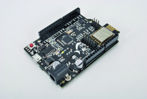
 

Viewing all 344 articles
Browse latest View live